Week -2
Aim:
- To make a Simulink model of doorbell using solenoid block with input details.
- To sense the temperature of a heater and turn on or turn off the fan as per below input conditions.
Governing equations:
1: doorbell:
The doorbell works on electromagnet principle. When the current is passed through a magnetic material(solenoid), electromagnetic field is generated which pulls the metal piston towards metal and comes to its original position when the current supply is off.
2: thermistor-controlled fan:
The working principle of this is based on the thermistor (NTC), the voltmeter compares the volage across the thermistor and the resistor where the voltage across the NTC will be greater than or equal to the voltage across the resistor which in return leads to negative or zero voltage resulting OFF for the transistor. If the temperature increases the initial value then the resistance decreases and voltage at it.
Explanation:
1: doorbell:
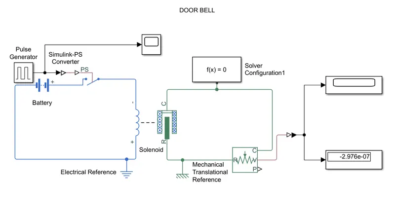
- In the Simulink model-1 the blocks used are pulse generator, solver configuration, solenoid, electrical reference, mechanical translational reference, battery switch, display and scope block.
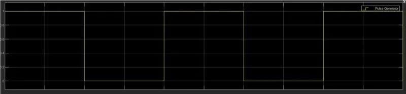
- The pulse generator is designed as per given time of 2 seconds and a ps-convertor is used to connect to a switch and then it is connected to a solenoid with the electrical reference.
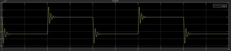
- The solenoid due to electro magnetism the pushes the piston to the metal making the sound. For this mechanism a translational motion sensor is added with a mechanical translational reference block and a solver configuration for the entire setup.
- This gives the output as pulse generation as shown in the figure.
2: thermistor-controlled fan:
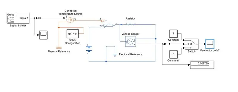
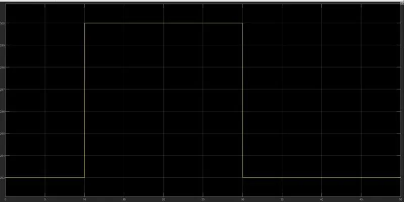
- As per given inputs the fan has to operate at various conditions so a signal builder has been given as an input the system where the input pulse is given in the means of temperature and time.
- A temperature source is added to generate heat and a thermistor is attached so that it generates the resistance in it with respect to the temperature with a thermal reference.
- A resistor is connected to circuit and a voltage sensor is placed so that the change is voltage due to change in temperature and resistance with a electrical reference and a battery.
- This setup is then connected to a switch which decides the on/off of the fan where the switch takes the input from voltage senor and compares the value with the conditions given to it (i>0) and sends the data to scope. A display box had been connected to the voltage sensor and a solver configuration block to the system.
Results:
generated input:
recieved output:
2: Thermistor-controlled fan:
input pulse:
generated fan motor output:
