Week-7 Challenge: DC Motor Control
1) Speed control of a DC motor using BJT-H bridge:
Objective:
- To explain the demo model of speed control of the DC motor using BJT-H bridge.
- To comment on the Armature current shoot-up.
- To compare the above model with the Four quadrant dc drive chopper DC7 block from the help section.
A)
Model:
Explanation:
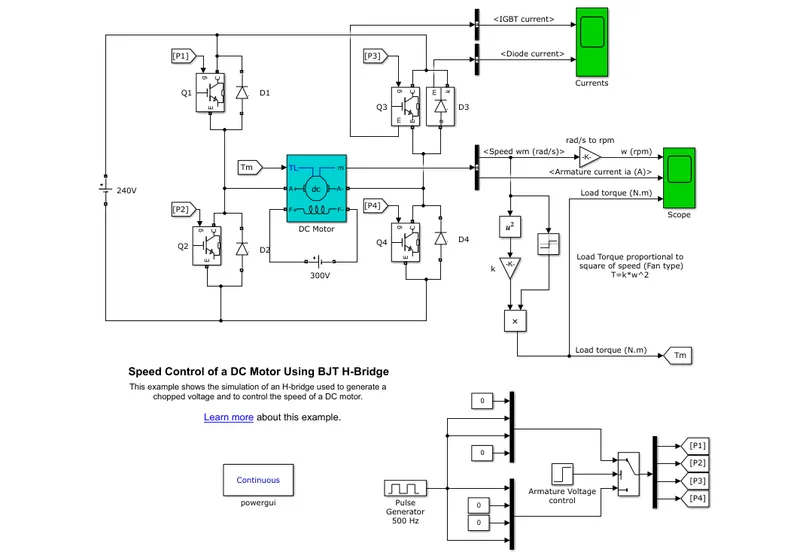
- The Speed control unit is H bridge which consists of IGBT and Diode.
- The pulse generator is used is to give the gate control signal to the IGBT.
- Since IGBT is used but the operation of the IGBT is same as BJT here, so it is called the speed control of dc motor using BJT H bridge.
- Due to high frequency switching rate, the losses are very low and speed control efficiency is very high.
- The Gate signal is produced by the Pulse generator.
- By controlling the Duty cycle of the Gate signal, the voltage applied to the motor is controlled. Hence the speed of motor is controlled.
- When the Q1 and Q4 is ON, the input voltage is applied across the DC motor.
- The voltage across the motor is positive and current through the load is also positive.
- Hence the mode of operation is in 1st
- While the Q1 and Q4 is turned ON, the Diode D2 and D3 freewheels.
- When the Q2 and Q3 is ON, the input voltage is applied across the DC motor.
- But the voltage applied across the dc motor is negative and current is also in negative direction.
- While the Q1 and Q4 is turned ON, the Diode D1 and D4 freewheels.
- By giving the external field current of 300V to the motor, it runs.
- And the Armature current and speed is obtained from bus selector to the scope.
- The speed is in rad/s is converted to the rpm and is observed in the scope.
- The load torque of a fan load is T = kω^2.
- This load torque is given as the mechanical input to the dc motor.
- And the load torque is observed in the scope.
Output:
Scope of IGBT Q3 and Diode D3 current:
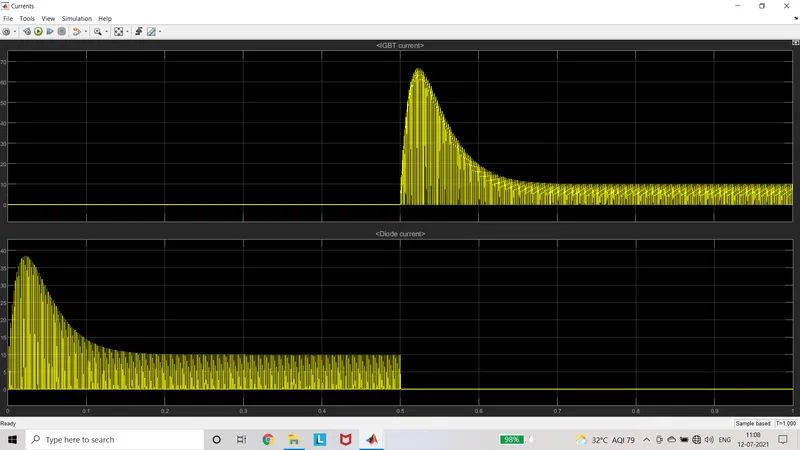
- During the Conduction of Q1 and Q4, the Diode D3 and D2 freewheels.
- During the freewheeling of D3, the current through the component D3 is shown in above output.
- During the Conduction of Q2 and Q3, the Diode D1 and D4 freewheels.
- During the conduction of Q3 the current through the component is shown, the current across diode D3 is zero and is shown in the output scope.
Scope of Armature current, Speed in rpm and load torque:
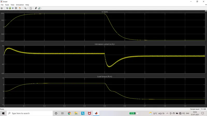
- During the on time of the Gate signal the armature current suddenly shoot-up and is reduced and maintained constant. During the OFF time of the gate signal, the armature current is reduced with sudden shoot-up and is maintained constant
- During the ON time of gate signal, speed is suddenly increased and maintained constant. When the gate is Off, the speed gradually decreases and reduced to the negative speed.
- The load torque curve is similar to the speed curve.
Result:
The working mode and operating region of speed control of DC motor using BJT H bridge is discussed.
- B) Armature Current Shoot-up:
By running the model with the default values, the pulse width of the gate signals (duty cycle) is given as 75%
There will be the sudden shoot-up during the transition state of ON and OFF time.
By reducing the duty cycle value to 45%, the model is simulated.
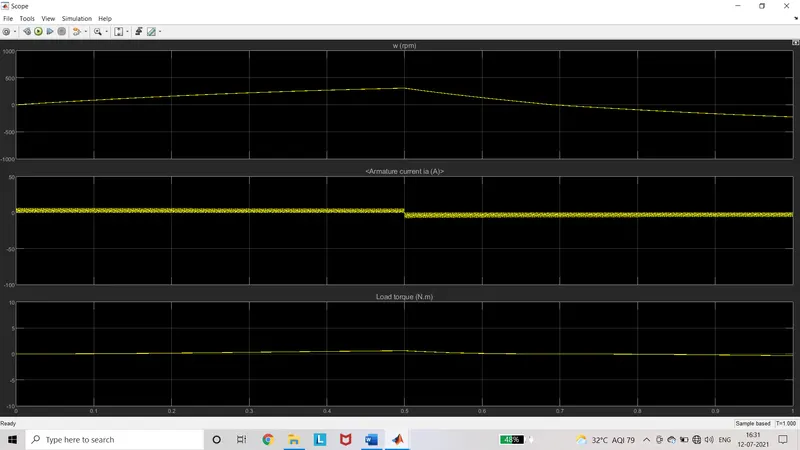
During this process the current shoot-up is reduced.
Therefore by adjusting the duty cycle to the corresponding value to get the current get maintained constant without any shoot-up during the transition.
And gradual increase in speed and torque is obtained.
- C) Comparing the H bridge model with the four quadrant chopper DC drive DC7 block:
Simulink Block:
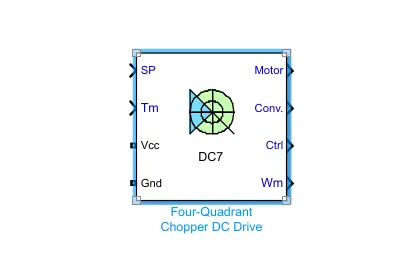
Simulink subsystem:
Blocks used:
- Speed Controller
- Current controller
- Regulator switch
- IGBT
- DC motor
- NOT
- Speed sensor
- Current sensor
- Constant(reference)
Overview:
- It is a closed loop control system.
- The circuit consists of 4 IGBT and 4 diodes.
- The gate pulses are produced by the speed controller, torque and current controller.
- The speed is controlled by the reference speed and the actual speed from the speed sensor.
- This is control speed is given to the regulator switch which gets the control from the reference torque.
- This switch gives the current reference corresponding to the speed and torque control.
- Then the current controller is used to give the gate pulse by comparing the reference with the actual current flowing through the load which is sensed by the current sensor.
- The IGBT 1 and IGBT4 is given with same gate pulse, IGBT2 and IGBT3 is given with same gate pulse.
- When the IGBT4 is On and IGBT 1 is operated the voltage from the supply is applied from the supply to the motor. The voltage is positive and current is positive. i.e) 1st
- When the IGBT is turned off, the diode D2 and IGBT4 conducts, the voltage and current is positive.
- When the IGBT4 is turned off, and IGBT2 is turned on the current from the source of dc motor carries the current through the IGBT2, D4. The voltage is positive and current is negative.
- When the IGBT2 is OFF, the current flow from load to source but voltage is positive, current is negative. i.e) 2nd
- When the IGBT2 is ON and IGBT3 is operated, the voltage and current is negative. i.e)3rd
- When IGBT3 is turned off, IGBT2 and D4 is freewheeled.
- When IGBT4 is operated, the voltage is negative and current is i.e)4th quadrant.
Comparison:
- 4 Quadrant chopper operates is four modes but H bridge operates in only 2 modes.
- Closed loop system is used in 4 quadrant chopper with regulator but it is absent in H bridge.
- The speed control is more efficient in 4 quadrant chopper than H bridge.
- Regenerative braking is possible in 4 quadrant chopper but is not possible in H bridge.
- Smoothing Inductance is used in 4 quadrant chopper for smooth operation of motor which is absent in H bridge.
- H bridge is used where forward and reverse motoring only is required.
- 4 quadrant chopper is used where the regenerative braking is used. Eg) Electric Vehicles.
2) Two Quadrant Chopper using Simulink:
Objective:
To create a model of two quadrant chopper using Simulink.
Circuit Diagram:
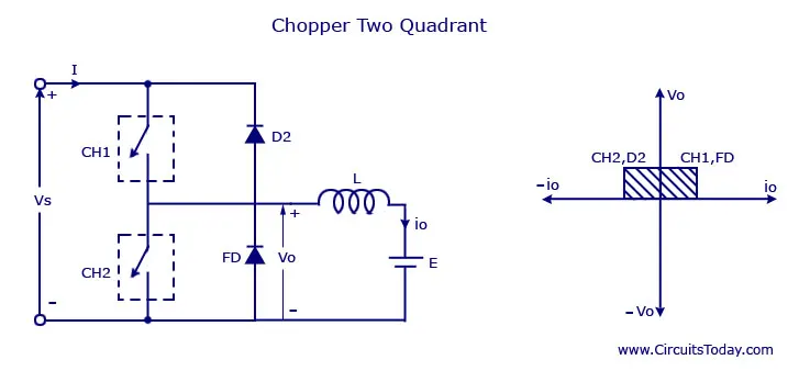
Blocks used:
- DC voltage source
- IGBT
- Diode
- DC machine
- Pulse generator
- Goto
- From
- Bus selector
- Gain
- Square
- Scope
- Product
- NOT
- Powergui
Model:
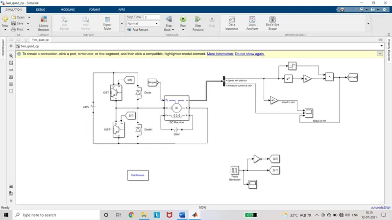
Procedure:
- Add the required blocks to the model
- Connect the required blocks as per the circuit diagram
- Configure the block parameters.
- The motor chosen is 5hp, 1750 rpm, field310v.
- The input voltage is 240V. In pulse generator, the pulse width is set to 70%.
- The gain value to convert the rad/sec to rpm is 60/(2*3.14).
- And the torque from the output is given as the mechanical input to the motor.
- Simulation time is set to 3 sec.
Explanation:
- The gate pulses are given in a way such that both IGBt’s are not operated simultaneously. If given it becomes the short circuit.
- When the IGBT is turned on, the supply voltage is applied across the motor and current flows through the motor. The voltage and current are positive.
- When the IGBT is turns off, the freewheeling diode operates. The voltage becomes zero and current is still positive passes through the L- E -FD because of energy stored in the inductor. 1st
- When the IGBT1 is turned on, the current flows from E to the IGBT1 hence the load current is negative.
- When it is turned off, the diode D freewheels and current flows from the load to source. 2nd Regenerative braking.
Output:
Gate Pulse:
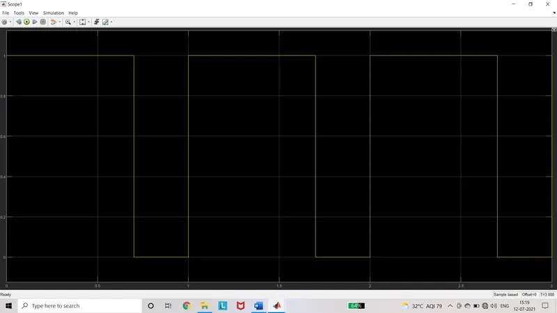
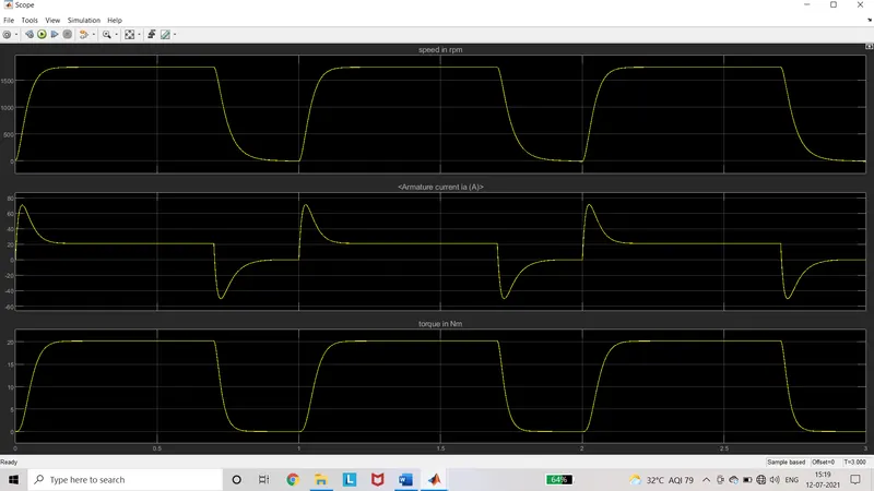
Output scope:
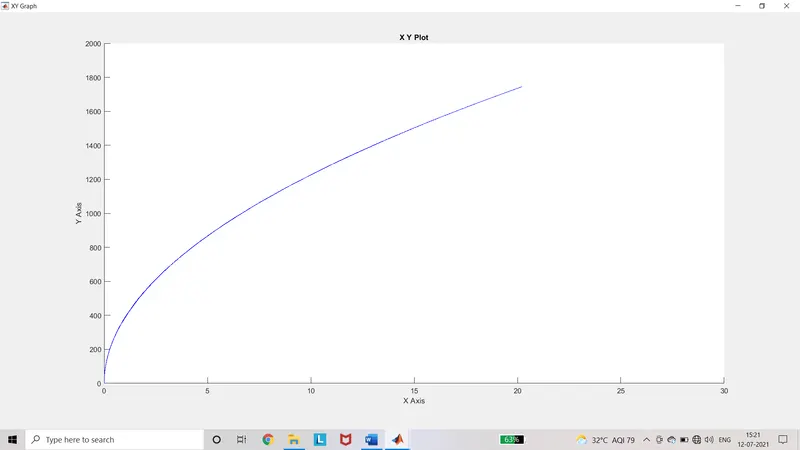
Torque Speed Characteristics:
Result:
The shoot-up armature current can be reduced by reducing the duty cycle, hence the torque and speed can be varied gradually. The two modes of operation are forward motoring and regenerative braking. Regenerative barking occurs when IGBT1 is turned off, the negative torque is produced for corresponding speed for regenerative braking.
3) Operation of BLDC motor:
Objective:
To explain about the operation of Brushless DC motor.
Explanation:
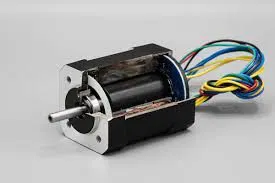
- Brushless DC motors are electronically commutated DC motor.
- In the brushed DC motor, Brushes and commutators are used, but in BLDC it is replaced by power electronic circuits.
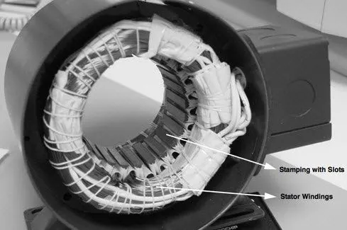
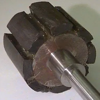
- It consists of stator, rotor, hall sensor and electronic control circuit.
- The rotor is a permanent magnet hence it does not require any power to brushes or commutator.
- The stator is the cylindrical fixed path with stator slots and teeth.
- In the slots the stator conductors are placed and insulated from short circuit.
- The 3phase supply is given to the stator with the help of the power electronic circuits.
Control:
- By changing the switching frequency, certain phases are excited to make the rotor to rotate.
- The hall sensors are used to find the position of the rotor poles.
- According to the position of rotor poles the stator conductors are excited to become a electromagnet.
- By the principle of attraction and repulsion the motor works.
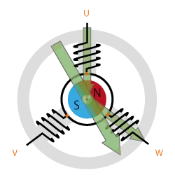
- When the current flows from U to W the resultant flux is in the direction as shown above.
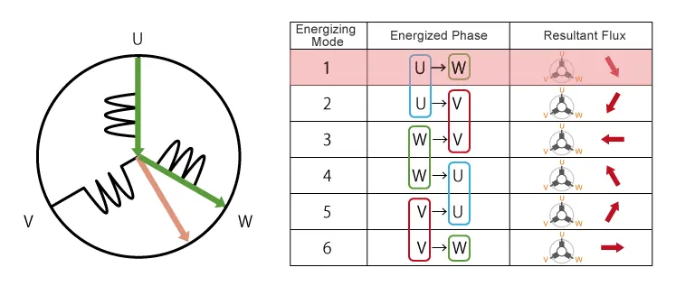
- And when the current is between U and V, and then series repeats as shown in the above diagram, the resultant direction is observed.
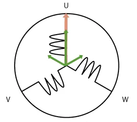
- This is obtained only with the help of electronic circuits because of their high switching frequency.
- The Control circuit consists of Controller logic and MOSFET bridge.
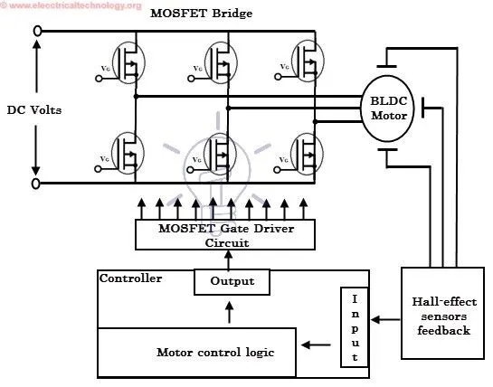
- The output the controller logic produces the gate drive signal to the MOSFET bridge.
- The output of MOSFET bridge is connected to the stator of BLDC motor.
- Whereas the input of the control logic is the hall sensor output and the driver input.
- The driver input is the position of the acceleration pedal and the brake pedal.
- The acceleration pedal position corresponds to the d1 duty cycle and brake pedal corresponds to the d2 duty cycle.
- The resultant of d1 and d2 and the hall sensor output is the output of motor control logic.
- PID controllers are used for precise speed control.
Advantages:
- High efficiency because there is no use of brushes and commutators, so brush loss I^2R and commutator losses are neglected.
- Speed control is very precise as it is controlled by the logic operations when driver gives the input.
- Long life and low maintenance.
- Operates at high speed at any condition by giving the additional intelligence to the controller such as hill climbing, wind velocity, road condition, etc.,
- No sparking and it exhibits the silent operation.
- Reduced in size and weight.
Limitations:
- Complex circuit in drives.
- Additional sensors.
- Heating if applied high voltage, hence voltage is limited.
- Cost is high.
Application:
- Hybrid electric vehicles and electric vehicles.
- Washing machine, refrigerator, air conditioner, dc fans.
- DVD players, Hard drive in PC’s