Week-7 Challenge: DC Motor Control
Aim:
1) a. Explain the MATLAB model ‘Speed control of a DC motor using BJT H-bridge’.
b. Comment on the armature current shoot-up from the scope results.
c. Also explain the model ‘The Four-Quadrant Chopper DC Drive (DC7) block’. Compare it with the H-bridge model.
2) Develop a 2-quadrant chopper using Simulink & explain the working of the same with the relevant results.
3) Explain in a brief the operation of a BLDC motor.
Software Used: Simulink
Aim 1:
Speed Control of a DC motor using H-Bridge:
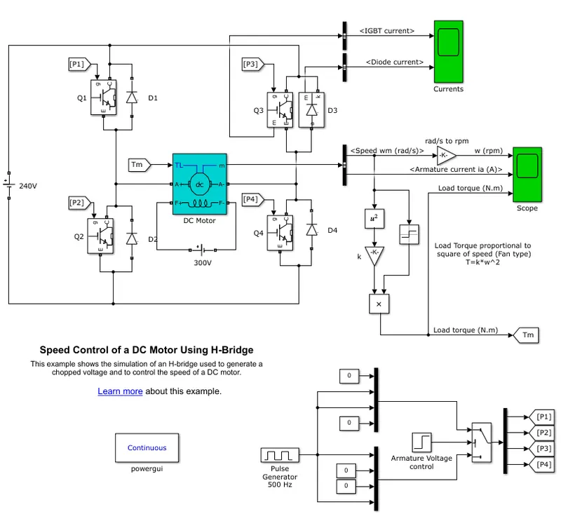
Construction of H-Bridge model:
- The H-bridge consists of four BJT (Q1, Q2, Q3, Q4) and Diode (D1, D2, D3, D4) pairs. BJT is simulated by using IGBT in this model.
- Each switch is controlled by a Simulink signal. P1, P2, P3, P4 are the signals that control the switches Q1, Q2, Q3, Q4 respectively.
- The control signals P1, P2, P3, P4 are generated as represented in the bottom right model in the image.
- The DC motor present in between the 4 BJT/Diode pairs uses the preset model i.e. 5 HP 24V 1750 rpm.
- The DC motor simulates a fan type load where Load torque is proportional to the square of speed. The armature mean voltage can be varied from 0 to 240 V when the duty cycle is varied from 0 to 100% using Pulse Width Modulation.
Working of H-Bridge model:
- Here, two transistors are switched simultaneously i.e. Q1 and Q4 or Q2 and Q3.
- When Q1 and Q4 are fired, a positive voltage is applied to the motor, and diodes D2-D3 operate as free-wheeling diodes when Q1 and Q4 are switched off.
- When Q2 and Q3 are fired, a negative voltage is applied to the motor, and diodes D1-D4 operate as free-wheeling diodes when Q2 and Q3 are switched off.
- When Q1 and Q3 or Q2 and Q4 are triggered, both sides of the motor have the same voltage and this is called brake mode.
- When Q1 and Q2 or Q3 and Q4 are triggered, it will result in a short circuit.
Simulation Results:
When we simulate the above model, we get the following results in the output ('Scope'):
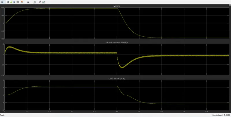
- Here, the motor starts in the positive direction with a duty cycle of 75% (mean DC voltage of 180V).
- At time t= 0.5 seconds, the armature voltage is suddenly reversed and the motor runs in the negative direction.
- 'Scope' shows motor speed, armature current and load torque.
- As the motor direction changes, the speed changes from around +1000 to around -1000.
- With the change in direction, the armature current also falls to a negative value. The thing to note is that there is a sudden shoot in armature current as the positive voltage is given. As the direction of the voltage applied changes, we see a sudden drop in the voltage.
- The shoot up/drop in armature current is due to the voltage fluctuation when there is a rise in vehicle speed. If we reduce our pulse width (duty cycle), the speed is reduced and thereby minimizing armature current shoot up/drop.
- Also, the load torque value changes from positive to negative as the motor changes direction. The load torque is calculated as shown above in the model i.e. `T=k*omega^2`
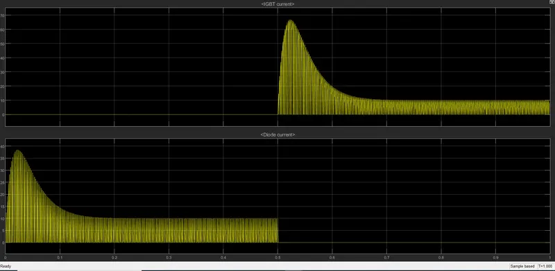
- We can also connect the scope to the IGBT and Diode combinations to know the flow of currents in them. In this case, the flow of currents through Q3 and D3 is as shown in the plot below i.e. from 0 sec to 0.5 sec, the current flows through the Diode D3 and from 0.5 sec to 1 sec, the current flows through the IGBT.
The Four-Quadrant Chopper DC Drive (DC7) block Model:
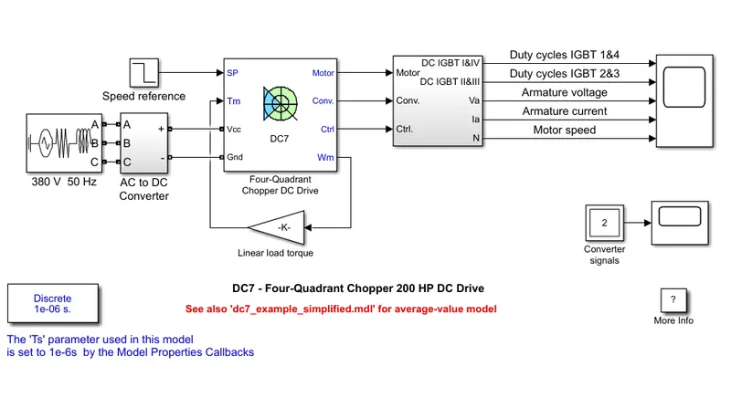
Four-Quadrant Chopper DC Drive:
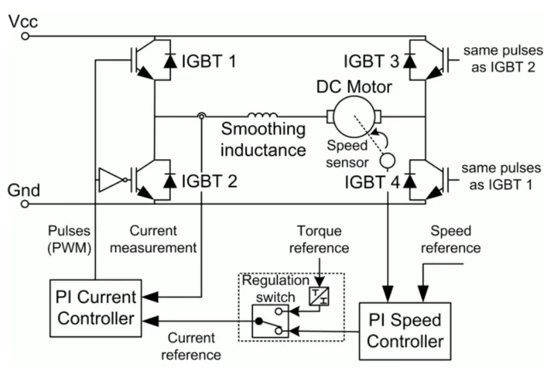
Sub-System attached to the right of Four-Quadrant Chopper DC Drive:
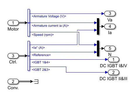
Construction of Four-Quadrant Chopper DC Drive (DC7) block model:
- The Four-Quadrant Chopper DC Drive consists of a 200 HP DC motor that is separately excited with a constant 150 V DC field voltage source.
- The armature voltage for the DC Motor is provided by an IGBT converter controlled by two PI regulators.
- The Four-Quadrant Chopper DC Drive is fed by a 515 V DC bus obtained by rectification of a 380 V AC 50 Hz voltage source.
- In order to limit the DC bus voltage during dynamic braking mode, a braking chopper has been added between the diode rectifier and the DC7block.
- Four-Quadrant Chopper DC Drive has two regulators. The first regulator is a speed regulator, followed by a current regulator.
- The speed regulator outputs the armature current reference (in p.u.) used by the current controller in order to obtain the electromagnetic torque needed to reach the desired speed. The speed reference change rate follows acceleration and deceleration ramps in order to avoid sudden reference changes that could cause armature over-current and destabilize the system.
- The current regulator controls the armature current by computing the appropriate duty ratios of the 5 kHz pulses of the four IGBT devices (Pulse Width Modulation). For proper system behavior, the instantaneous pulse values of IGBT devices 1 and 4 are opposite to those of IGBT devices 2 and 3. This generates the average armature voltage needed to obtain the desired armature current.
- In order to limit the amplitude of the current oscillations, a smoothing inductance is placed in series with the armature circuit in a Four-Quadrant Chopper DC Drive.
- All the outputs we get from the Four-Quadrant Chopper DC Drive i.e. Armature Voltage, Armature Current, Motor Speed, Duty Cycles of IGBT 1&2, Duty Cycles of IGBT 2&3 are obtained and connected to scope for viewing.
- We can also individually see the control signals of the IGBT pair. The scope below the main scope i.e. the one connected to converter signals shows us the control signals of IGBT 2&3.
Working of a Four-Quadrant Chopper DC Drive:
- The IGBT's in Four-Quadrant Chopper DC Drive receive their control signals as shown in the Four-Quadrant Chopper DC Drive figure above.
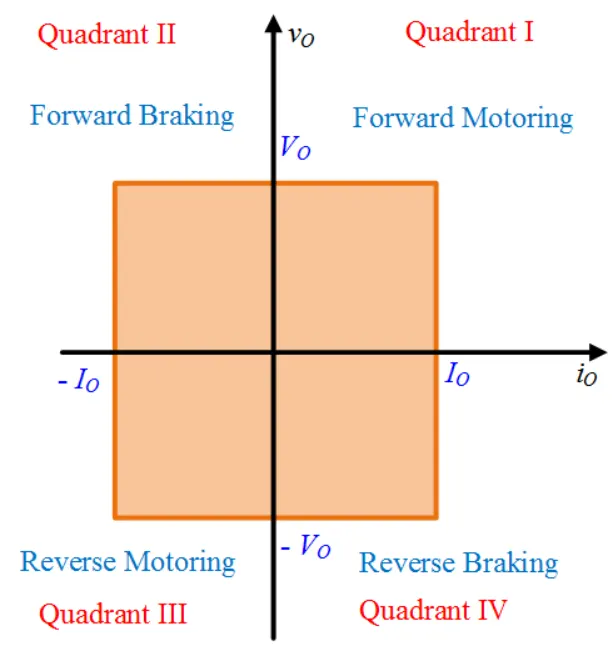
- This chopper can be operated in all four quadrants. The power can flow either from source to load or load to source in this chopper. The vo-io plane shows that this machine operates in all 4 quadrants. In the plane, vo is output and Vo is the average output voltage. io is output current and Io is the average output current.
- Let us now simplify the figure of Four-Quadrant Chopper DC Drive as shown below before studying its operation in detail
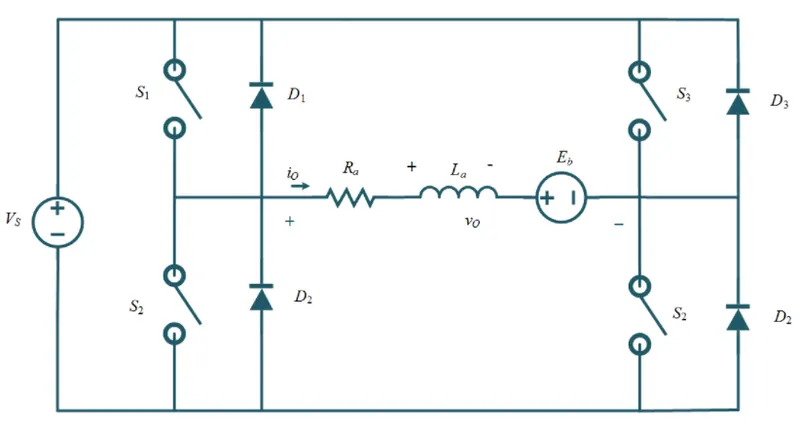
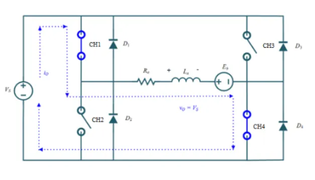
- First Quadrant Operation: For the first quadrant operation, CH4 is kept ON, CH3 is kept OFF and CH1 is operated. When both CH1 & CH4 are ON simultaneously, the load gets directly connected to the source and hence the output voltage becomes equal to the source voltage. This essentially means that vo = vs. It may be noted that the load current flows from source to load as shown by the direction of io.
 When CH1 is switched OFF, the load current freewheels through CH4 and D2. During this period, the load voltage and current remain positive.
 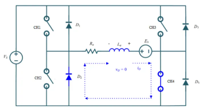 Thus, both the output voltage vs and load current io are positive, and hence, the operation of the chopper is in the first quadrant. It may be noted that this chopper operates as a step-down chopper in this case.
 - Second Quadrant Operation: To obtain second quadrant operation, CH2 is operated while keeping the CH1, CH3 & CH4 OFF. When CH2 is ON, the DC source in the load drives current through CH2, D4, E, and L. Inductor L stores energy during the On period of CH2.
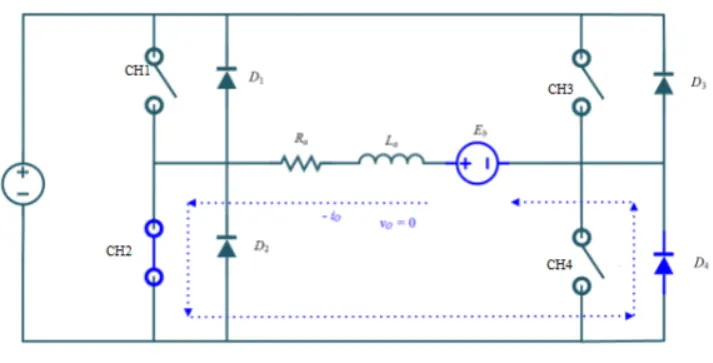 When CH2 is turned OFF, the current is fed back to the source through D1, D4. It should be noted at this point that (E+Ldi/dt) is more than the source voltage Vs. As load voltage Vo is positive and Io is negative, it is the second quadrant operation of the chopper. Since the current is fed back to the source, this simply means that load is transferring power to the source.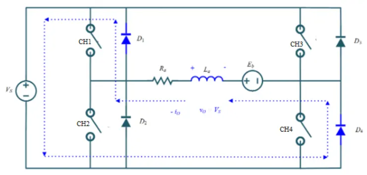
For the second quadrant operation, the load must contain emf E as shown in the circuit diagram. In the second quadrant, the configuration operates as a step-up chopper.
- Third Quadrant Operation: To obtain a third quadrant operation, both the load voltage and load current should be negative. One important thing to notice is that the polarity of emf E in load must be reversed to have a third quadrant operation.
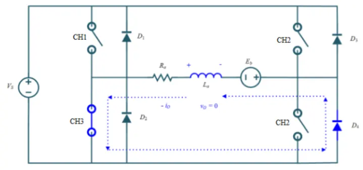
For the third quadrant operation, CH1 is kept off, CH2 is kept ON and CH3 is operated. When CH3 is ON, the load gets connected to the source and hence load voltage is equal to source voltage. But carefully observe that the polarity of load voltage vo is opposite to what shown in the circuit diagram. Hence, vo is assumed negative. Let us now see what is the status of load current io. It may be seen that io is flowing in the direction opposite to shown in the circuit diagram and hence negative.
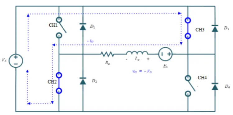
Now, when CH3 is turned OFF, the negative load current freewheels through the CH2 and D4. In this manner, vo and io both are negative. Hence, the chopper operates in the third quadrant.
- Fourth Quadrant Operation: To obtain the fourth quadrant operation, CH4 is operated while keeping CH1, CH2, and CH3 OFF. The polarity of load emf E needs to be reversed in this case too like the third quadrant operation. When CH4 is turned ON, positive current flows through CH4, D2, L, and E. Inductance L stores energy during the time CH4 is ON.
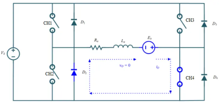 When CH4 is made OFF, the current is fed back to the source through diodes D2, D3. Here load voltage is negative but the load current is always positive. This leads to chopper operation in the fourth quadrant. Here, power is fed back to the source from the load, and the chopper acts as a step-up chopper.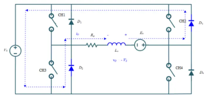
Simulation Results:
When we simulate the above model (The Four-Quadrant Chopper DC Drive (DC7) block Model), we get the following results in the output scope connected to the Duty Cycles, Armature Voltage, Armature Current and Motor Speed:
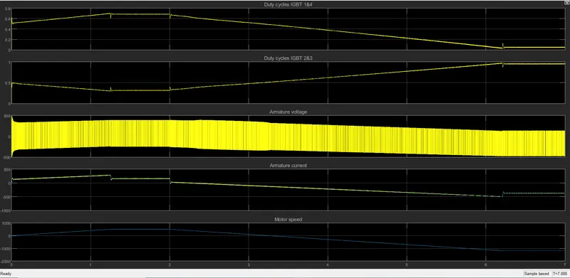
- The motor is coupled to a linear load, which means that the mechanical torque of the load is proportional to the speed.
- At t = 0s, the speed reference is set at 500 rpm. Observe that the motor speed follows the reference ramp accurately (+400 rpm/s) and reaches steady-state around t = 1.3s.
- The armature current follows the current reference very well, with fast response time and small ripples. Notice that the current ripple frequency is 5kHz.
- At t = 2s, speed reference drops to -1184 rpm. The current reference decreases to reduce the electromagnetic torque and causes the motor to decelerate with the help of the load torque.
- At t = 2.2s, the current reverses in order to produce a braking electromagnetic torque (dynamic braking mode). This causes the DC bus voltage to increase.
- At t = 3.25s, the motor reaches 0 rpm and the load torque reverses and becomes negative. The negative current now produces an accelerating electromagnetic torque to allow the motor to follow the negative speed ramp (-400 rpm/s).
- At t = 6.3s, the speed reaches -1184 rpm and stabilizes around its reference.
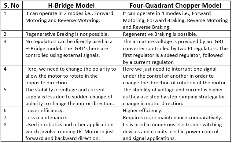
Comparison between H-Bridge Model and Four-Quadrant Chopper Model:
Aim 2:
Two-Quadrant Chopper:
Construction of a Two-Quadrant Chopper:
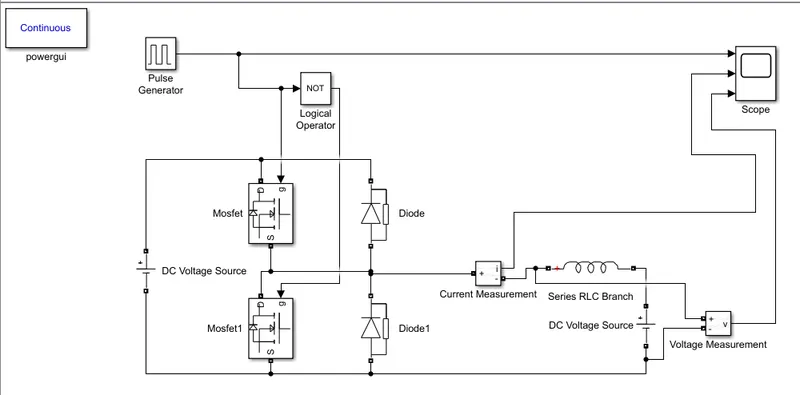
- Here we have a pulse generator with amplitude 10, period 0.02 sec, pulse width 50%, and all other values set to default.
- These signals of the pulse generator are given to the MOSFETs via a logical operator (not gate) in order to prevent the short circuit caused due to the operation of both MOSFETs.
- Each MOSFET has a diode connected in parallel to it and they are energized via a DC voltage source (24V).
- This MOSFET and diode circuit is connected to an inductance and a secondary DC voltage source (12V).
- The values of all other components are set to default. Voltage and current measurement devices measure the output voltage and current from the circuit and are connected to a scope along with the output of the pulse generator in order to compare the changes in the voltage and current with respect to the pulse generator output.
Working of a Two-Quadrant Chopper:
- Two-Quadrant Chopper can operate in the first as well as the second quadrant. This basically means that the power can either flow from source to load or load to source in this chopper and the voltage is always positive. In the below plot, Vo represents output voltage and Io represents the output current.
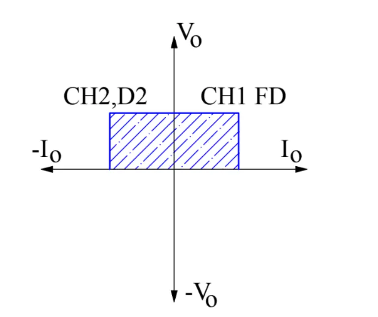
- In the above Two-Quadrant Chopper circuit, CH2 is represented by Mosfet 1, D2 is represented by Diode, CH1 is represented by Mosfet, and FD is represented by Diode 1.
- First Quadrant Operation: When Mosfet is switched ON, DC voltage source directly gets connected to the load and hence, load voltage Vo is equal to source voltage. The direction of load current is from source to load which is assumed positive.
When Mosfet is switched OFF, the free-wheeling Diode 1 comes into the circuit as it gets forward biased and hence shorts the load. Therefore, the output voltage Vo becomes zero. However, the Io continues to die down through the Diode 1 and Inductance in the same direction. Thus, the average output voltage Vo and current Io are positive and hence the operation of the chopper is in the first quadrant.
-
Second Quadrant Operation: When the Mosfet 1 is switched ON, the current flows from the load DC voltage source to the Mosfet 1. The direction of this current Io will be opposite i.e. right to left and hence is assumed negative. Output voltage Vo is zero during this time. When Mosfet 1 is made OFF, Diode gets forward biased and hence the current enters into the source from the load. Voltage is positive in this case and the load current is always negative i.e. operation of the chopper is within the second quadrant.
Simulation Results:
When we simulate the Two-Quadrant Chopper model, we get the following results in the output scope:
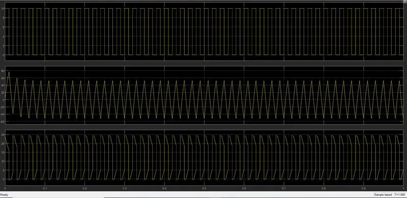
- Here, the first plot shows the pulse generator output. The second plot shows the current output versus time and the third plot shows the output voltage versus time plot.
- If you carefully see, the output voltage waveform is not going less than zero i.e., the voltage is always in the positive direction.
- However, you can see that the current increases and decreases, and it goes negative as well based on the freewheeling action.
Aim 3:
Operation of a BLDC Motor:
- Consider the following setup of three windings in the stator designated A, B, and C. For the sake of understanding, let us replace the rotor with a single magnet.
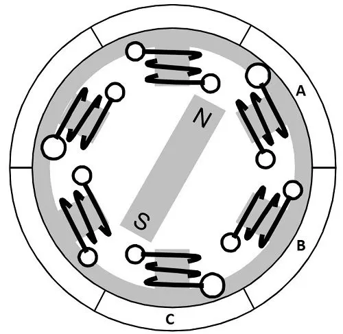
- We know that when a current is applied through a coil, a magnetic field is generated and the orientation of the field lines i.e. the poles of the generated magnet will depend on the direction of the current flowing through the coil. Using this principle, if we supply current to coil A so that it will generate a magnetic field and attract the rotor magnet. The position of the rotor magnet will shift slightly clockwise and will align with A. Then, if we pass current through coils B and C one after the other (in that order), the rotor magnet will rotate in a clockwise direction.
- To increase efficiency, we can wind the opposite coils using a single coil so that we get the double attraction. Further increasing the efficiency, we can energize two coils at the same time so that one coil will attract the magnet and the other coil will repel it. During this time, the third will be idle. For a complete 3600 rotation of the rotor magnet, six possible combinations of the coils A, B, and C are applicable and are shown in the following timing diagram:
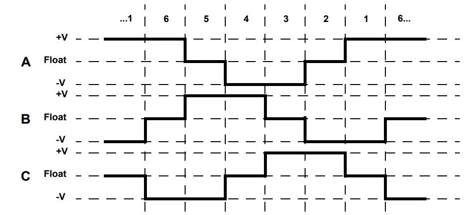
- Based on the above diagram, we can confirm that at any time, one phase is positive, one phase is negative and the third phase is idle (or floating). So, based on the inputs from the Hall Sensors, the switching is done.
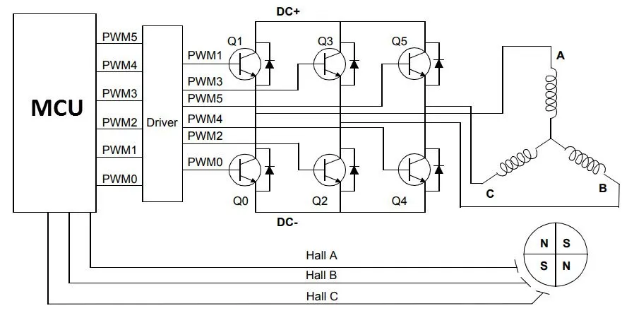
- If stator and rotor are essential parts of a BLDC Motor that are integral to it, then the driving electronics are equally essential. A Block diagram of a typical Brushless DC Motor control or drive system is shown in the following image:
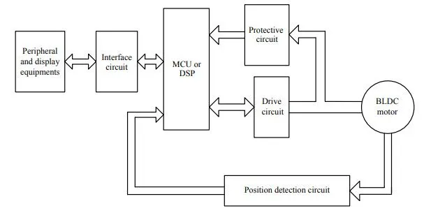
- This drive circuitry is often known as Electronic Speed Controller System or simply an ESC. One common setup is called the Full-Bridge Drive Circuit. It consists of an MCU with PWM outputs, six MOSFETs for the three phases of the stator windings, feedback from the Hall sensors, and some power supply-related components. The MCU can be programmed to appropriately switch the MOSFETS based on the data from the Hall Sensors.