Week-7 Challenge: DC Motor Control
1.
A) Explain a MATHLAB demo model named 'speed control of a DC motor using BJT H-bridge'.
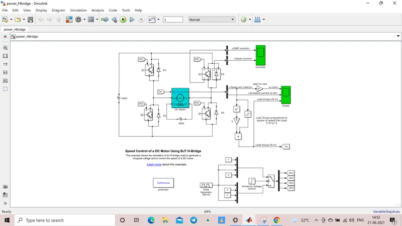
The above demo model of speed control of a DC motor using BJT H-bridge can be obtained by enterin the command 'power_Hbridge' in the command window.
Here the DC motor will work according to the signal outputs of the BJT/IGBT. Here the BJT and diodes are placed as similar to H-bridge.
A simple diagram as shown below can explain the working of an H-bridge.
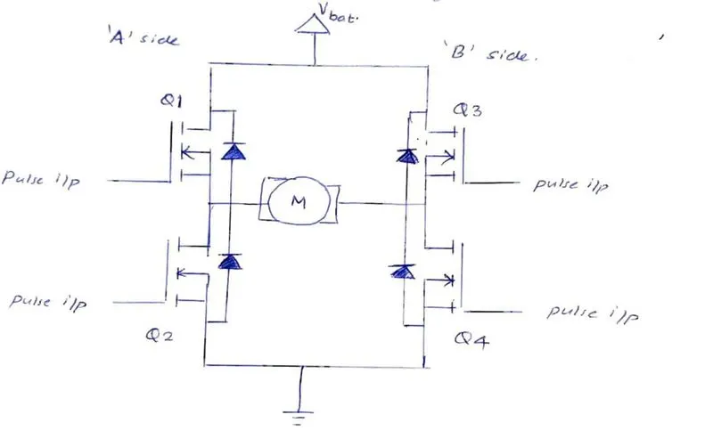
In general, an H-bridge is a simple circuit which contains switching elements with the load at the center in an H like configuration.
It has four switching elements which is either BJT/IGBT/MOSFET.
The BJT have three terminals i.e emitor, collector and base. The power is connected between collector and emitor and the control is connected between base and collector.
Switching of these BJT have a pattern:
Switching ON Q1 & Q4 in which Q2 & Q3 are in OFF state, the current flows from V(bat) through Q1 to motor and the to Q4 and flows back to the ground aif switch is in open state.nd the diodes D3 & D4 freewheels Here forward motoring happens.
Switching ON Q2 & Q3 in which Q1 & Q4 are in OFF state, the current flows from V(bat) through Q3 towards motor and then towards Q3 and flows back to the ground and dioses D1 & D4 freewheels if the switches are in open state.Here reverse motoring happens.
If Q1,Q2,Q3,Q4 are in open state, There is no potential across the motor and this mode is known as Braking mode
If Q1,Q2,Q3,Q4 are in closed state at same interval of time, The circuit becomes short circuited and there may be a chance of burning happening.
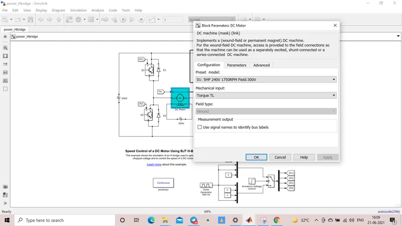
Here the default configuration of the dc motor is 5HP, 240V, 1750RPM with a field of 300V.
The below displayed graph shows the waveform at Q3 andthe diode D3.
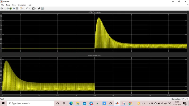
Here the simulation is run for 1 second and for 0 to 0.5 sec diode conducts and 0.5 to 1 sec IGDT conducts.
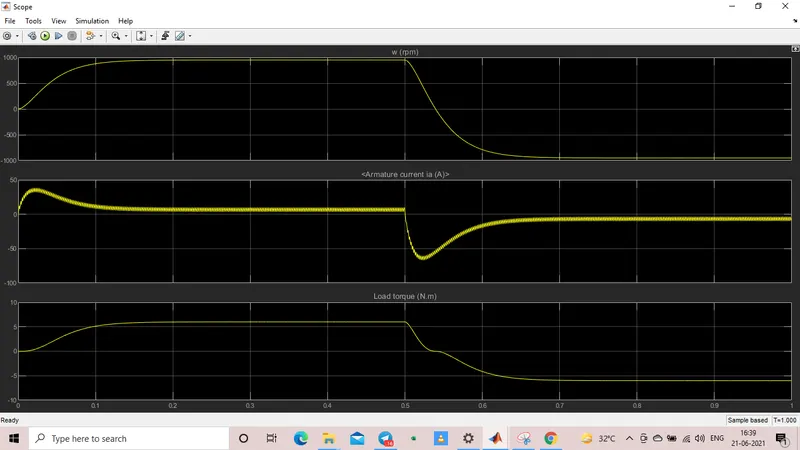
The below shown plot is a scope output of speed, armature current and load torque.
Here load torque is directionaly proportional to the square of the speed of the dc motor.
1.
B) Comment on the armature current shootup from the scope results.
Here from the scope results we obtained the plots of speed (rpm), armature currentv(A), Load torque(Nm).
Here the duty cycle is at 75% and we can see a sudden surge in armature current plot and accordingly the speed and load torque too increases. After a period of 0.5 seconds the speed is been reversed all of a sudden and the armature current also shoot up in the reverse direction. This shoot up is occuring because of the trasient switching happening in the circuit.
We can reduce the shootup value by changing some parameters in the pulse generator i.e duty cycle. Here we can see that the value of pulse width is changed to 50% from 75%.
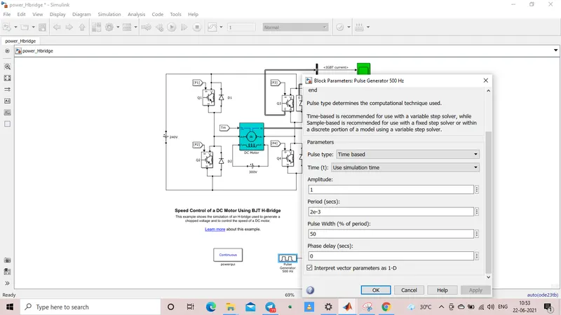
After changing the pulse witdth to 50%, we can't see a sudden shoot up in the armature current.
The logic behind this is when the pulse width is reduced to 50%, the voltage across the motor terminal also get reduced and as a result the current also reduces which too reduces the speed and load torque.
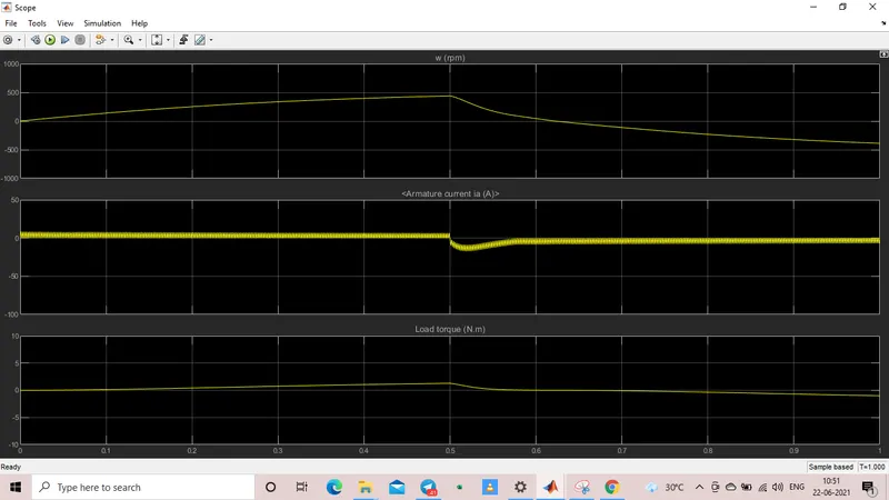
In this observation the shootup of armature current reduced from 70% pulse width to 50% pulse width.
1.
C) Refer to the help section of 'The four quadrant chopper DC drive (DC7) block'. Compare it with the H-bridge model.
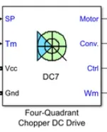
A DC7 block signifies a four quadrant chopper, i.e the speed control is achieved by four quadrant operation in a DC motor.
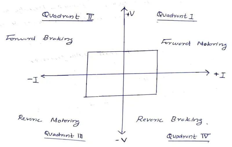
The four quadrant chopper can work in all four quadrants i.e
Quadrant 1 : both Current and voltage positive : Forward motoring.
Quadrant 2 : voltage positive and current negative : Forward braking.
Quadrant 3 : Both voltage and current negative : Reverse motoring
Quadrant 4 : Voltage negative and current positive : Reverse braking
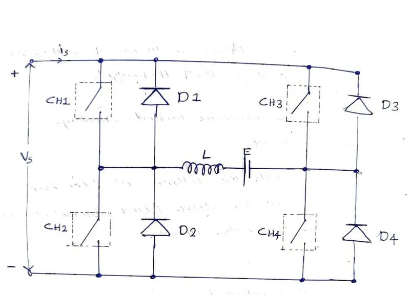
Four quadrant circuit diagram:
It is also called a class E chopper where CH1, CH2, CH3 and CH4 are choppers and D1, D2, D3 and D4 are diodes.
Quadrant 1 operation : Here CH1 is operated and CH4 in ON state and CH3 and CH2 in OFF state.
When CH1 & CH4 is ON, the current passes through CH1-DC load-CH4 and to the negative terminal, i.e Vo = Vs.
When CH1 is OFF, load current free wheels through CH4 & D2, Here load voltage and current ar positive, Hence the operation is in first quadrant.
Quadrant 2 operation : Here CH2 is operated, CH1, CH3, CH4 is in OFF state.
When CH2 is ON, DC source in the load drive current through CH2-D4-E-L.
When CH2 is OFF, Current is fed back to the source through D1 & D4. Here E+L*(d/dt)*i is more than source voltage Vs. Here Vo is positive and Io is negative, It is second quadrant operation and here the load is transfereing power to the source.
Now the polarity of the load emf E is reversed to have a third and fourth quadrant operation.
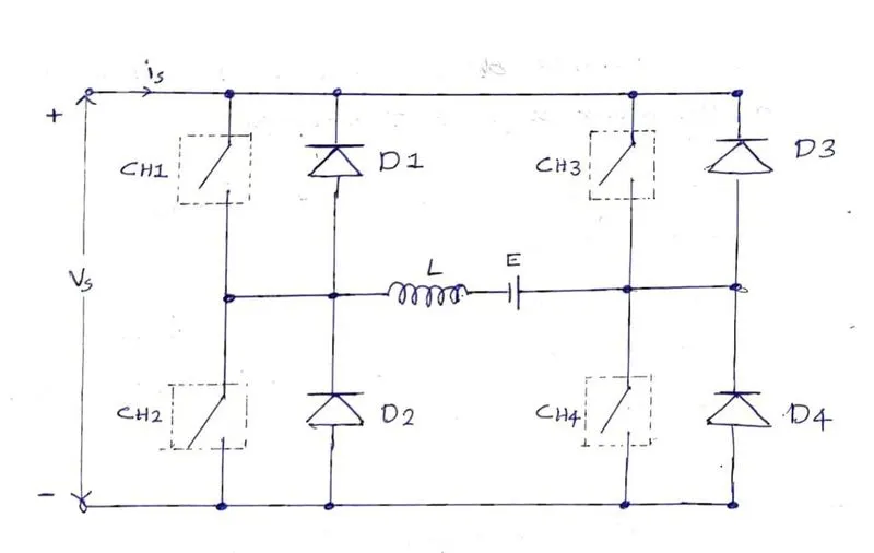
Quadrant 3 operation : Here CH3 is operated, CH1 is kept OFF and CH2 in ON state.
When CH3 is in ON state, The current flows from +Vs-CH3-Load-CH2--Vs. Here polarity of the load voltage is opposite, hence the load voltage and current is negative. (current is negative because it changed its regular direction.)
when CH3 is in OFF state, Current freewheels through CH2&D4, so chopper operates in 3rd quadrant.
Quadrant 4 operation : Here CH4 is operated and CH1, CH2, CH3 are in OFF state.
When CH4 is in ON state, current flows from CH4-D2-L-E.
When CH4 is in OFF state, current is fed back through D2 and D3.
Here load voltage is negative and load current is positive. Thus it operates in fourth quadrant.
Comparison of four quadrant chopper & BJT-H bridge.
| Four quadrant chopper | BJT-H bridge. |
|
Works in four modes, i.e Forward motoring mode Forward braking mode Reverse motoring mode Reverse braking mode. |
Works only on two Quadrants. Forward motoring Reverse motoring. |
| To change the direction of the motor, the current signal get transited from one to another switch | to change the direction of the motor, the polarity of current changes. |
| High switching frequency | Low switching frequency |
| Armature current have littile spike due to high swithcing frequency | high spike in armature current. |
| used in industrial application | Used in robotics |
2.
Develop a two quadrant chopper using simulink & explain the working of the same with the relevant results. (Refer to article - multiquadrant operation of motor.)
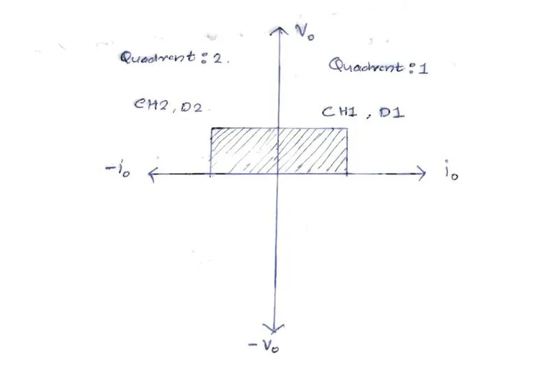
A two quadrant chopper is also called a type C chopper. It can operate in quadrant 1 and quadrant 2.
Here we always get a positive output voltage as freewheeling diode is present across the load.
It is a combination of class A and class B chopper.
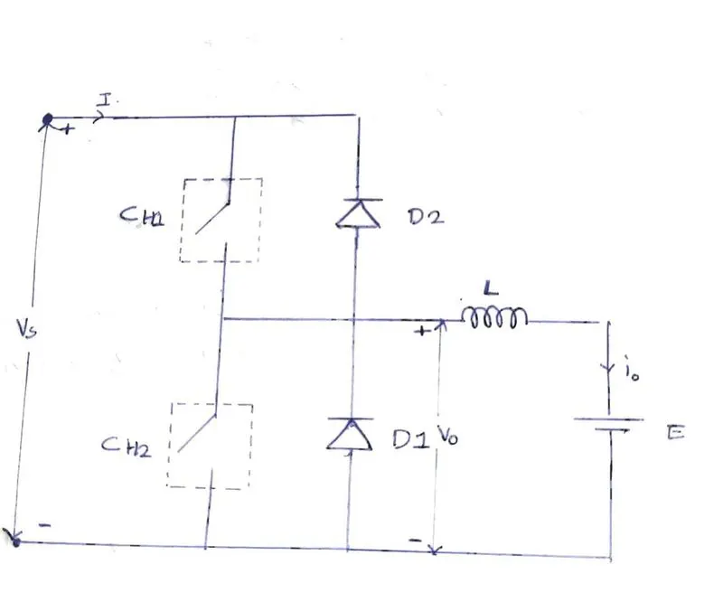
Quadrant 1 operation :
CH1 is operated here, When CH1 is in ON state, the path of current is (+Vs - CH1 - load - -Vs) i.e the voltage source charges the inductor.
when CH1 is OFF, Inductor discharges and the current freewheels through D1.
Here current and the voltage are in the direction indicating 1st quadrant operation.
Quadrant 2 operation:
Here CH2 is operated, When CH2 is ON, EMF of the load will charge the inductor, current flows from (E - L - Ch2 loop).
When CH2 is turned OFF, inductor discharges through D2 i.e the path is ( L- D2- Vs - E). Here the current is negative and voltage is positive indication a second quadrant operation.
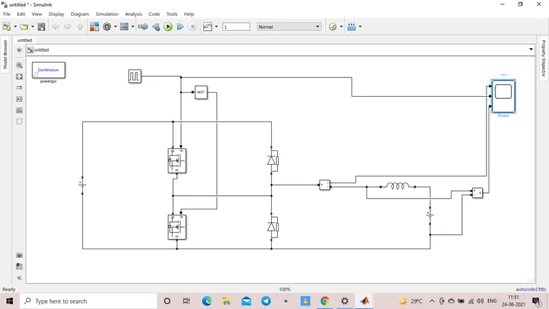
The simulation of two quadrant chopper is done as follows. here the simulation time is set to 1.
Here we use a pulse generator, a logic gate, mosfet, diode, scope, current and voltage measurement, dc voltage source, power GUI and a series RLC band.
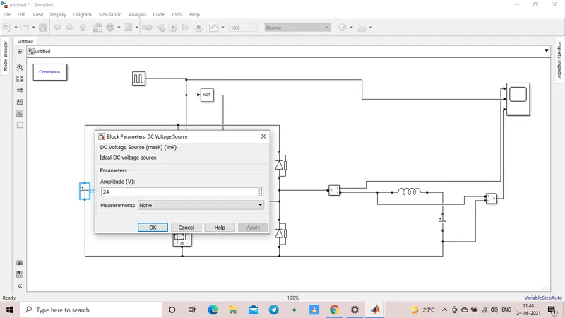
The DC source voltage is provided with 24V.
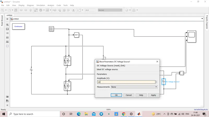
The EMF source here is taken half of the DC voltage source i.e 12V.
The pulse generator configuration is done by giving the amplitude of pulse as 10 with a period of 0.02seconds and a duty cycle of 50%.
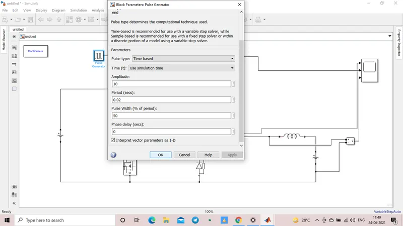
The simulation is then made run and the result is obtained as shown below.
1. pulse generator output.
2. voltage across the load.
3.current in the load.
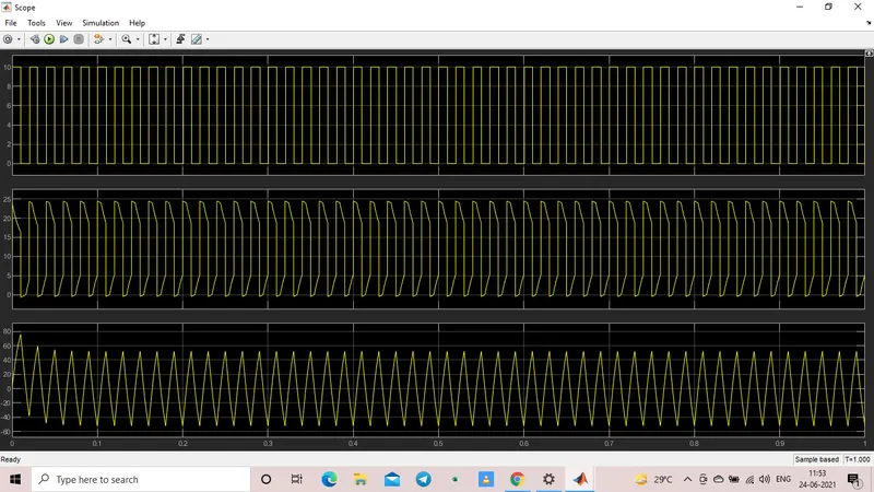
The result obtained is then zoomed
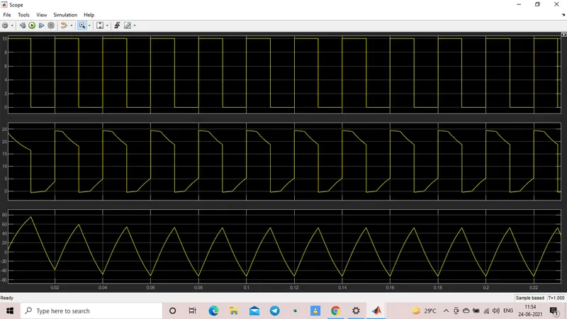
result:
here the voltage is not going below zero, and maximum value is in the positive direction.
The current increases and decreases and it also moves in the negative direction too based on the switiching action.
i.e we can conclude that in this type of chopper the voltage is always positive and current can be both positive and negative which gives the output in 1st and 2nd quadrant.
3. Explain in a brief about operation of a BLDC motor
It is a Brushless DC motor with electronic commutator.
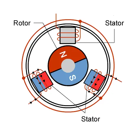
Here we have an electronic commutator or a power converter where it energizes different turn by turn.
Most of the brushless DC motor are of three phase type.
For brushed type DC motor, there is no harm in working it with no load but here we cannot connect simply a voltage terminal across the brushless type because it have three terminals. So to connect a three terminal motor with two terminal source we need a commutator in between.
The rotor have a fixed permanent magnet that is why it is called a permanent magnet brushless DC motor.
The stator have core with windings. when current flows through the poles it acts as a magnet.
Three phase current have to be maintained synchronously in such a way that the motor rotates in clockwise/anti-clockwise direction.
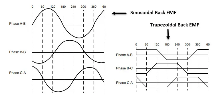
There are two arrangement in which the BLDC motor works:
1. Trapezoidal arrangement
2.sinasoidal arrangement.
The input waveform provided to the stator side of the BLDC motor for the respective arrangement is shown below.
The BLDC motor also use a Hall effect sensor.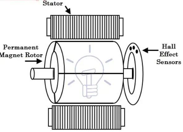
the hall effect sensor provides the information to stator armature excitation with rotor position