Final Project: Design of an Electric Vehicle
Create a MATLAB model of electric car which uses a battery and a DC motor. Choose suitable blocks from power train blockset. Prepare a report about your model including the following:
Objectives:
1) System level configuration.
2) Model parameters.
3) Results.
4)Conclusion.
INTRODUCTION:
An Electric car is a car that is propelled by one or more electric notors, using energy stored in rechargable batteries. Compared to internal combustion engine (ICE) vwhicles, electric cars are quieter, have no exhaust emissions, and lower emissions overall.
Electric car function by plugging into a charge point and taking electricity from the grid. They store the electricity in rechargable batteries that power an electric motor, which turns the wheels. We can charge an EV by plugging it into a public charging station or into a home charger.
There are different types of EV. Some run purely on electricity and it is called as pure electric vehicle and some can run in both petrol/diesal and batteries which are called Hybrid EV's.
1. Plug-in electric : The car runs purely on electricity and gets all its power when it's plugged in to charge. It doesnot need petrol/diesal to run, thus it doesnot produce any emission.
2. Plug in hybrid : The plug in hybrid mainly run on electricity but also have a traditiional fuel engine so that we can use petrol/diesal is battery is run out of charge. Plug in hybrid can also be pluged in to an external source for charging the battery.
3. Hybrid-Electric : These run mainly run on fuel but also have a battery which is recharged through regenerative braking. These vehicle cannot be plugged into an electricity source.
An electric car work as when the car pedal is pressed, the controller takes and regulates electrical energy from batteries and inverters.With the controller set, the inverter then sends a certain amount of electrical energy to the motor (according to depth of pressure on the pedal.) Electrical motor converts electrical energy into mechanical energy ( rotation). Rotation of motor rotor rotates the transmission so the wheels turn and then the car moves.
The components used in an EV is as shown below in the picture.
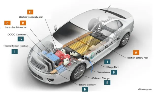
The main components used are:
1. Traction battey pack:
It stores electrical energy in the form of direct - current electricity. If it gets a signal from the controller, the DC electrical energy will flow to the converters and the converter converts the DC energy into required energy ( stepped up DC or AC if induction motors are used).
There are different types of batteries used and the widely used and the efficient one is the lithium-ion battery.
2. Controller:
The controller is the brain of an EV. The controllers regulates the electrical energy from batteries and converters that will be distributed to electrical motors.The controller gets the input from car pedals which is controlled by the driver. This unit manages the flow of electrical energy delivered by the traction battery, controlling the speed of the electrical traction motor and the torque it produces.
3. Converters:
The converter function is to change the DC current into step up DC , Step down DC current for brushless DC motors or inverter functioning for converting DC to AC for induction motors.
Converters also convert the energy generated at regeneration to dc type which charges the battery.
4. Electric traction motor:
The motor/machine converts the electrical energy from convertor to equivalent rotational torque which helps the vehicle move. It also acts a generator and gives back power to the battery which interms charges the battery.
The simulation of electric vehicle can be bulit according to the block diagram shown below.
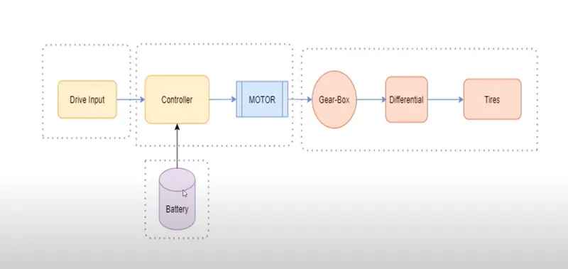
The whole model can be divided into four parts.
1. vehicle body: In vehicle body we can see tire, chasis, gearbox.
2. Motor and controller: Here we can use different types of motor and controlling mechanism. Here we use a simple DC motor for simulation.
3. Drive input: Here we can create input/reference signal with the help of inbuild drive cycle, signal builder block, excel sheet etc.
4. Battery: Power provided to run the motor is provided from the battery.
In this block diagram motor will provide mechanical energy to gear box for the operation where it takes power from the battery which are interconnected through a controller which controlles the supply from battery to motor.
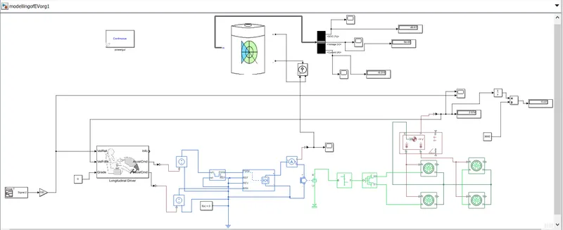
The overall connection after the modelling is shown below:
SYSTEM LEVEL CONFIGURATIONS AND MODEL PARAMETERS:
The first block to be addded is the vehicle body from simscape library. Here vehicle body is having six ports.
1. H -Hub
2. V - Actual speed of vehicle.
3. W - Wind velocity.
4. beta - inclination of road.
5. NF - Normal force for front wheels.
6. NR - Normal force for rear wheels.
Modelling of the vehicle body part.
- Add the vehicle body from simscape library.
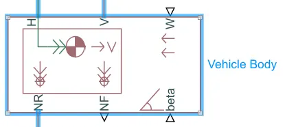
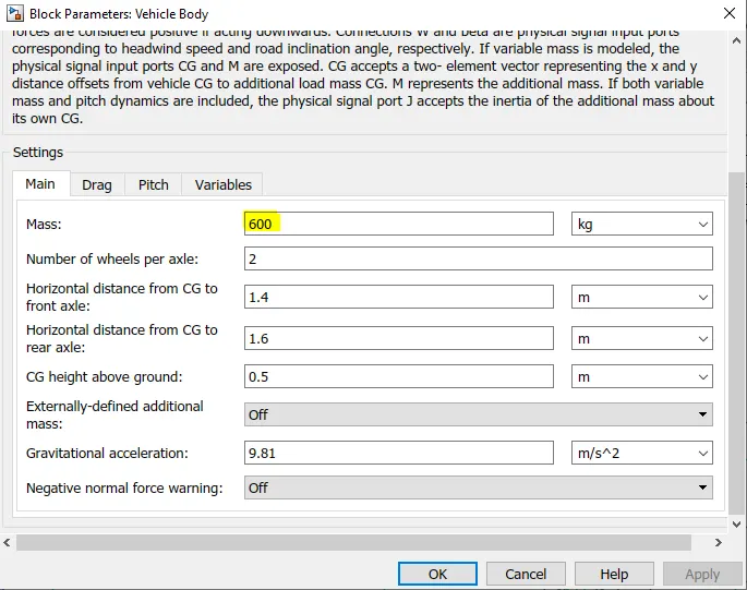
- We can change the vehicle body parametrs by double clicking the block.
- Here mass of the vehicle is changed to 600kg.
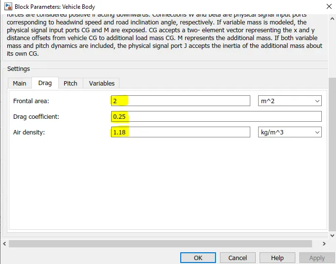
- Here Drag variable can also be changed as shown below.
- Add tires from simscape library
- As we are modelling an elecrtic car we can add four number of tires.
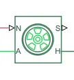
- The Tire has four ports:
- 1. N - Normal force port.
- 2. Axle.
- 3. Hub.
- 4. Slip.
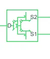
Add Differential from simscape library
With the help of differential we can include the inertai and losses from gear.
The D side is connected with the simple gear and S1 and S2 ports are connected with the axles of the tire.
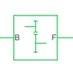
Now add simple gear and connect the F terminal of the gear with D terminal of the differential.
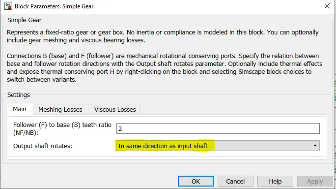
To get positive velocity change the parameter of the gear box to "In same direction as input shaft".
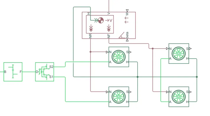
Modelling of vehicle body can be done as shown in the connection diagram below.
Here the NR port of the vehicle body is connected with the N ports of rear wheels and NF port of the vehicle body is connected with the N of the front tires.
The Hub of vehicle is connected with the hub of all tires.
The simple gear is connected with the differential and the S2 and S1 ports are connected to the rear wheel axles.
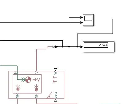
From this subsystem we will examine the actual speed of the vehicle.
To plot V of vehicle body we need to add a scope, display and a PS-simulink converter to convert the physical quantity to digital quantity because the scope and display is a digital block.
Here we need to change the output signal unit of the PS-Simulink converter to km/hr.
The connection diagram is as shown below.
MOTOR AND CONTROLLER PART.
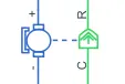
Add DC motor from simscape library and H-bridge converter to convert the DC motor.
Here brushed type permanent magnet motor is used for simplicity.
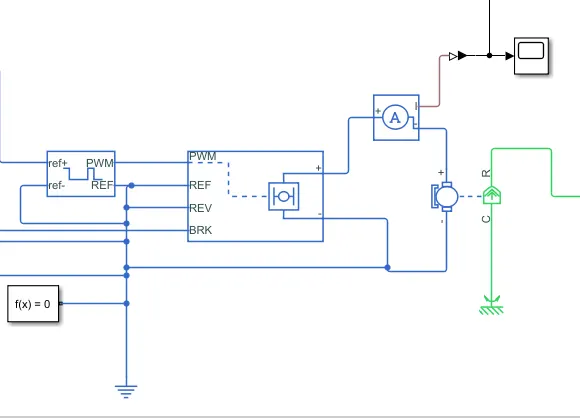
The supply after controlling is connected to the positive and negative terminals of the motor and the R is the shaft output which is then connected to the simple gear in the vehicle body parts. Here R is the reference.
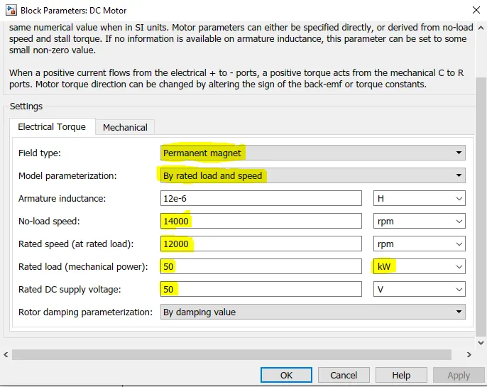
In motor block parameters, The field type is changed to permanent magnet and model parameterization is changed to rated load and speed.
The no-load speed is changed to 14000 rpm and Rated speed is changed to 15000 rpm.
The mechanical power (Rated load) is changed to 50KW and rated DC supply voltage to 50V.
If our rated speed is less then we will get more difference between the reference speed and actual speed.
If we are getting more difference between actual speed and reference speed then we can reduce the difference by increasing the rated speed or by decreasing the vehicle body weight.
Add the H-bridge block
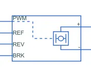
With the help of H bridge we can perform the acceleration, braking and reverse mechanism.
The bridge require power supply to operate. The H bridge power supply can be managed externally and internally.
To reduce the simulation time we change the simulation mode to averaged and always enable regenerative braking option to allow work the H bridge in the braking mode too.
The load current characteristics is changed to smoothed type.
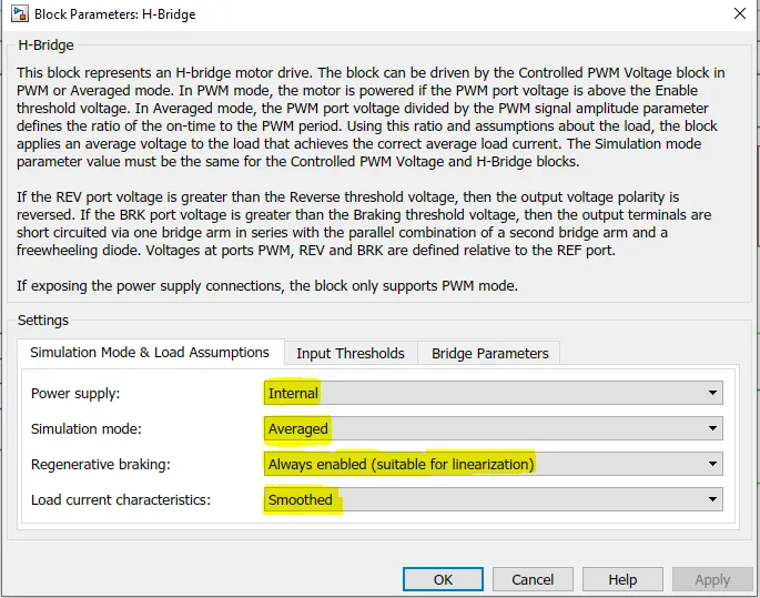
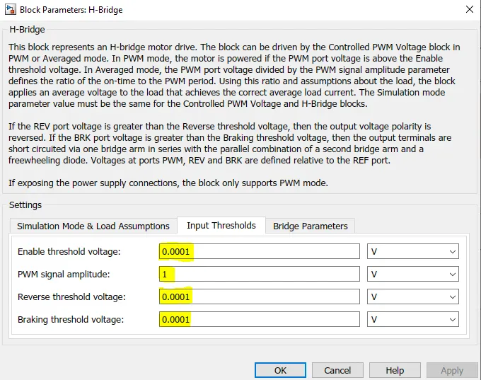
We can change the treshold voltage, PWM signal amplitude, Reverse threshold voltage, Braking treshold voltage to the required value to get an optimized model.
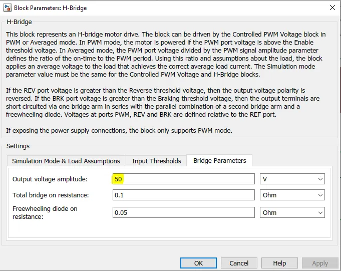
Under bridge parameter, change the outputvoltage amplitude to 50V.
To measure the current to the motor we need a current sensor block.
The mechanical reference block is added which is connected to the R port of the motor to provide a reference signal.

We have to control the PWM signal of the H bridge. For that we add control PWM voltage block

Here this block gets the input from the driver.
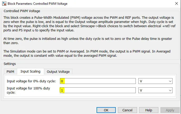
Here to reduce simulation time we changed the simulation time to averaged
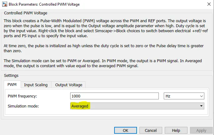
Here input voltage for 0% duty cycle is made 0 and input voltage for 100% duty cycle is 1.
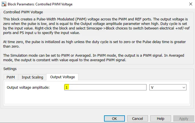
Under output voltage, the output voltage amplitude is changed to 1V.
Here we use a PS-simulink converter to convert the physical signal into digital one to connect the current sensor output.

A scope is also added to plot the current graph.

A electrical ground is used to connect the negative terminals to a common ground.

A solver configuration block is also added for accuarcy.

The conection diagram of motor and controller is shown below.
Driver input:
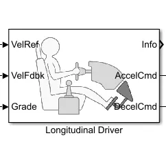
Add longitudinal driver from power train blockset.
In the longitudinal driver block we provide it with a reference drivecycle by adding an inbuild drive cycle or by creating our own signal with the help of signal builder block.
Here we also connect the actual speed of the vehicle to the velocity feedback port.
The grade can also be changed by connecting a constant value to the block.
Thus we get an acceleration command and deceleration commant from the ports which can be connected with the H- bridge.
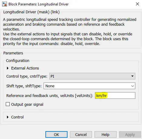
Here the reference and feedback units, velunits[velunits] as km/hr
Here we take a constant value to provide a grade signal to the longitudinal block.

Here the acceleration and braking command output can be directly connected to the H brige. So we use a simulink to PS converter which converts the digital signal to physical signal.

A controlled voltage source is added from simscape library because this block has the ability to provide the same voltage throughout the circuit.

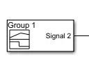
A drive signal is constructed using a signal creator block
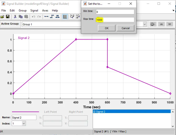
Here we are creating a signal builder for 1000 seconds, thus changing the maximum time to 1000 seconds.
Here the speed linearly increased from 0-400 seconds and for next 200 seconds the speed is made 100km/hr.
Then speed is decreased to 50 km/hr and that decreases.
We can change this signal according to our own driving cycle.
The below shown is the created signal.
A constant block is added to decide maximum speed (with a value of 100).

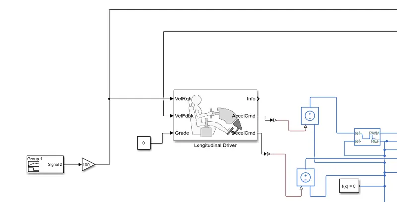
The connection diagram of the driver subsystem is as shown below.
Here the feedback velocity from the vehicle body is provided to the longitudinal driver block.
The signal generator is connected to the velocity reference block.
The acceleration command and braking command is provided to the control PWM voltage block and H-bridge brake port respectively.
The grade here is considered as 0 as the vehicle is considered moving in a flat road.
Battery subsystem:
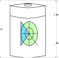
Add the battery block from library.
The benefit of this battery is it provides direct SOC% but it may take more time for simulation.
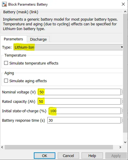
Here in parameters we selected the li-ion type battery.
Here the nominal voltage and rated capacity to 50V.
Here the initial state of charge is kept at 100%.
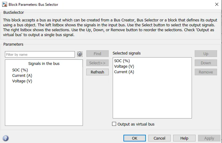
Add bus selector block from the library.
Here we can add the signal as per our requirement.

Here SOC%, voltage, current are selected.
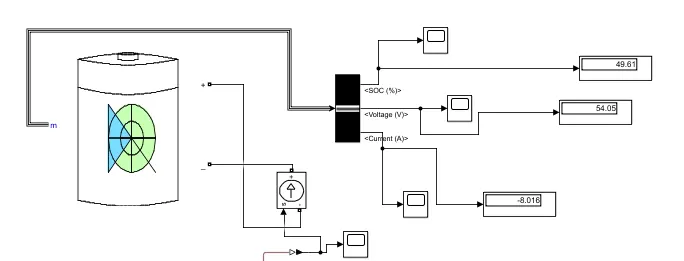
Here scope and dispaly are connected to the bus selector to display the SOC%, current and voltage.
Add controlled current source, it will provide a constant current through out the ciircuit.

The connections are made as per the below diagram for the battery subsystem.
The current flowing from the H-bridge internal source to the DC motor is sensed using a current sensor and that value is provided to the battery subsystem.( we should also note that during acceleration the current will flow from battery to motor and during braking the current flows from DC motor back to the battery.
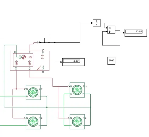
The measurement of distance travelled can be calculated by Distance = speed/time
Here we integrate the velocity output from the vehicle body where we get the speed and divide it by 3600 seconds to get the distance travelled by the vehicle in hours.
To build a block we need an integrator.

A divide block

A constant block with 3600 as constant value.

a display

The distance calculation connection diagram is shown below.
A power gui block is also added which opens a graphical user interface that displays dteady-state values of measured current and voltages as well as static variables. It also allows you to modify the initial states in order to start the simulation from any initial conditions.
Result:
The distance covered by the vehicle is displayed in the simulink model.
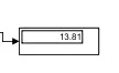
In this drive cycle the distance travelled is 13.81km.
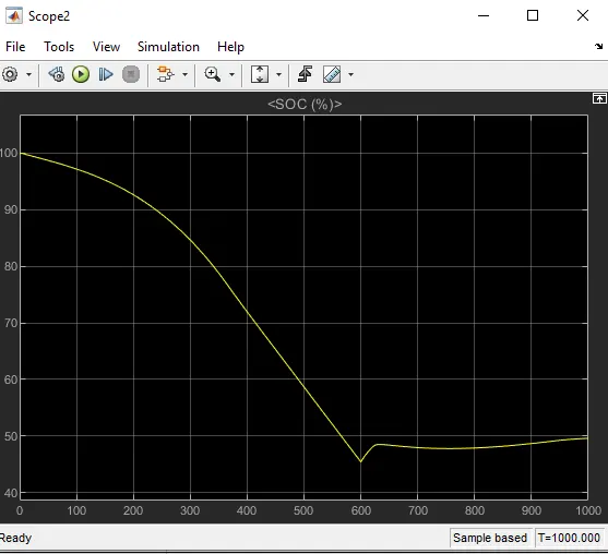
SOC% plot:
The battery has discharged non linearly for initial 400 seconds and for the next 200 seconds the battery has discharged linearly.
From 600 seconds the battery has charged and discharged considering the feedback.
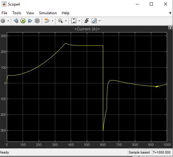
The current plot is shown below.
The current has increased from 0 to 250A during acceleration and reveresed the direction during the braking condition.
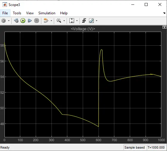
The voltage plot is also shown below.
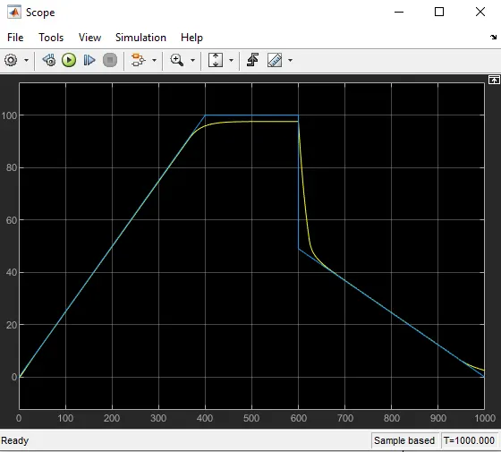
The actual and reference velocity graph is shown below.
Here actual speed is trying to follow the reference speed
We have limited the top speed to 100km/hr usinga gain block.
Here the blue plot is the reference speed and the yellow plot is the actual speed of the vehicle. Here we can see the yellow plot following with the reference plot but not able to co-inside.With improved technology and low vehicle weight we can reduce the distance betwwen those two plots which increases the vehicle efficiency.
Conclusion
The modelling of an Electric car and its simulation is done.
Here the model depends on many factors such as drive cycle, type of motor used, efficiency of the converter, vehicle body parameters and many more. By intelligently designing all those factors, by checking and retesting with many probable values, we can conclude the electric car with better efficiencies in different conditions.
With better understanding we can reduce the gap between the actual vehicle speed and vehicle reference speed and improve battery, motor and power converter efficiencies.