Week-7 Challenge: DC Motor Control
1. A. The objective is to explain the MATLAB demo model named ‘Speed control of a DC motor using BJT H-bridge’.
- Firstly, BJT is nothing but Bipolar Junction Transistor a power semiconductor device used in power switching applications.
- When the BJT is conducting, a forward voltage is been passed through the collector and emitter region.
- In this model, The Bipolar Junction Transistor (BJT), when used for power switching applications, operates as an IGBT ( Insulated gate Bipolar Transistor), which shares the same characteristic of BJT unless it has a gate terminal for gate voltage.
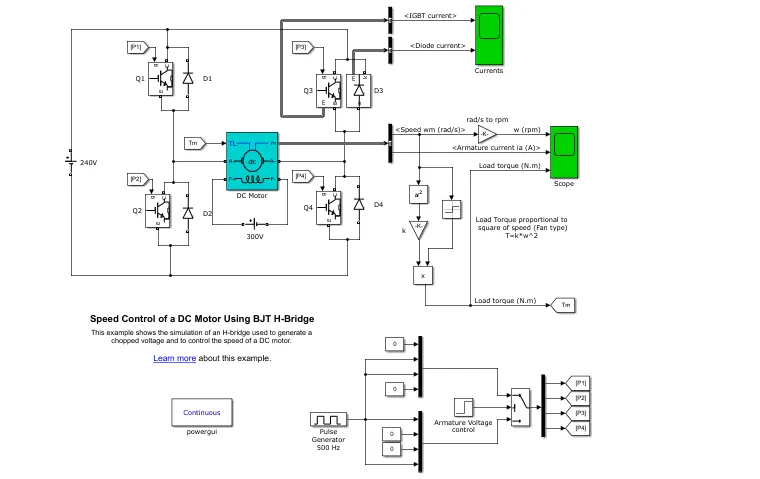
- The IGBT has been used in large voltage applications and switching frequency is good for several applications.
- To control the speed of DC Motor using the BJT bridge, four transistors and diodes are connected. In this, the two pairs are switched simultaneously, Q1 and Q4 or Q2 and Q3. When four pairs of transistors are switched at a time, then it leads to a short circuit.
- When the Q1 and Q4 switched are closed, then a positive voltage is applied to the motor and when Q1 and Q4 are switched off, then D2 and D3 act as freewheeling diodes.
- When the Q2 and Q3 switched are closed, then a negative voltage is applied to the motor and when Q2 and Q3 are switched off, then D1 and D4 act as freewheeling diodes.
- The armature voltage is fed by the source voltage and the field voltage is set as 300 V.
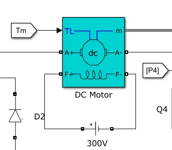
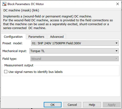
- The Preset model of the DC motor can be changed and the parameters set here are 5HP 240V 1750rpm.
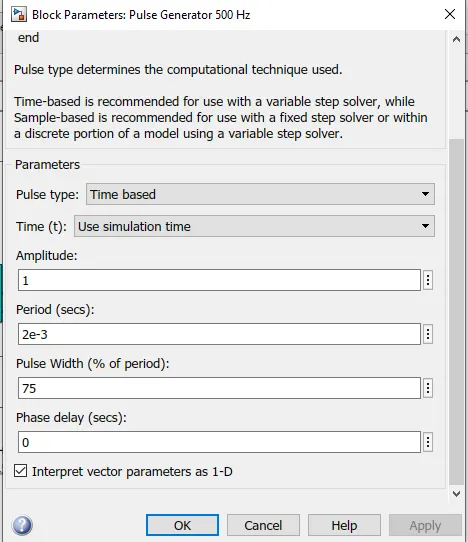
- The pulse generator block, the total time, and ON time and OFF time switching can be set. The pulse width denotes the ON time and OFF time.
- The duty cycle denotes the switching time (ON/(ON+OFF)).
- The pulse generator is connected to the transistors for the input pulse signal.
- The initial mechanical input to the DC motor is fed by a battery source connected to the motor and the mechanical movement represents the Torque.
- By observing the results, we can know that the torque generated is square of the speed attained by the motor.
T ∝ ω ^2
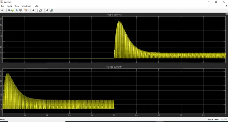
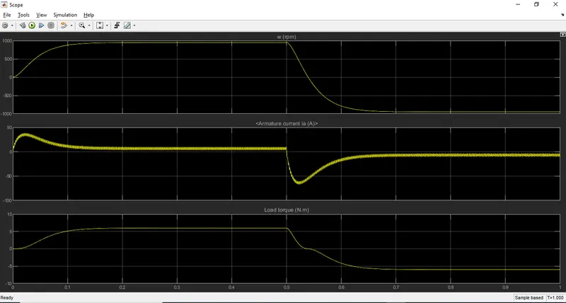
- The motor starts in the positive direction with a duty cycle of 75%. At t= 0.5 sec., the armature voltage is suddenly reversed and the motor runs in the negative direction.
B. The objective is to comment on the armature current shoot-up from the scope results.
- From the results analyzed of 'Speed control of a DC motor using BJT H-bridge’ with default parameters, it is observed that there is shooting up in the initial starting time of the motor.
- When Q3 is switched off, the starting current is carried by D3 up to 0.5 sec, and as a result, the speed takes as of a sudden in the simulation, therefore the armature current flows in a positive direction and the Load torque is in the forwarding direction.
- When Q3 is switched ON, the IGBT current starts flowing after 0.5 sec, and as a result, the speed reduces as of a sudden in the simulation, therefore the armature current flows in a negative direction and the Load torque is in the reverse direction.
- In order to reduce the shoot-up armature current, we can reduce the pulse width from the pulse generator.
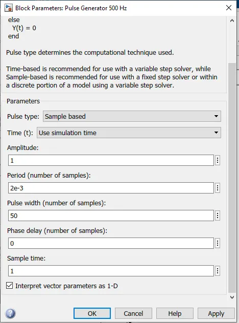
- The Pulse width is reduced from 75 to 50 and these pulse signals are given to the transistors.
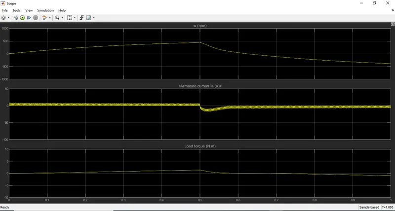
- By analyzing the results, the shoot up of the armature current is reduced and therefore we can conclude that the armature shoot up can be reduced by reducing the pulse width parameter.
C. The objective is to analyze 'The Four-Quadrant Chopper DC Drive (DC7) block’ and compare it with the H-bridge model.
- The Four Quadrant chopper is a power semiconductor switching device that helps the motor to work in all four Quadrants. The motor can achieve Forward Motoring, Forward Braking, Reverse Motoring, Reverse Braking.
QUADRANT I:
- In this quadrant, the motor draws voltage from the source.
- The direction of voltage and current is the same.
- This Quadrant is referred to as Forward Motoring.
QUADRANT II:
- In this quadrant, the current direction is changed keeping the voltage polarity as it is.
- The direction of voltage is positive and the current is negative.
- As result, braking is applied to the motor
- The direction of the speed is positive and the direction of the torque is negative.
- The negative torque opposes the speed which results in a braking
- This braking is called Regenerative Braking
- The power is fed by the motor to the source.
- During Braking, the Kinetic energy in the mechanical parts is transferred as electrical energy to the source.
- This Quadrant is referred to as Forward Braking.
QUADRANT III:
- In this quadrant, the motor and current polarity are changed
- As a result, the motoring direction is reversed
- The direction of speed and Torque are negative but the motor stills rotate but in the reverse direction.
- This Quadrant is referred to as Reverse Motoring.
QUADRANT IV:
- In this quadrant, the voltage direction is changed.
- The direction of voltage is negative and the current is positive.
- As result, braking is applied to the motor during reverse motoring.
- The direction of the speed is negative and the direction of the torque is positive.
- This braking is called Reverse Regenerative Braking
- The power is fed by the motor to the source.
- During Braking, the Kinetic energy in the mechanical parts is transferred as electrical energy to the source.
- This Quadrant is referred to as Reverse Braking.
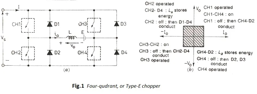
- All switches should not be switched on time.
- CH1 and CH2 should not switch at a time or CH3 and CH4 which can lead to a short circuit.
- When CH1 and CH4 is switched ON, then the power flows through the circuit, and the inductor stores a small amount of energy
- This operation is done in First Quadrant.
- When CH1 and CH4 are switched OFF, the inductor releases the stored energy, and D1 and D4 conduct.
- This operation is done in Second Quadrant.
- When CH2 and CH3 is switched ON, then the negative voltage and current flows through the circuit, and the inductor stores a small amount of energy
- This operation is done in Third Quadrant.
- When CH1 and CH4 are switched OFF, the inductor releases the stored energy, and D2 and D3 conduct.
- This operation is done in Fourth Quadrant.
Four-Quadrant Chopper DC Drive (DC7) block
- The 200 HP DC motor is separately excited with a constant 150 V DC field voltage source.
- The armature voltage is provided by an IGBT converter controlled by two PI regulators.
- The converter is fed by a 515 V DC bus obtained by rectification of a 380 V AC 50 Hz voltage source.
- In order to limit the DC bus voltage during dynamic braking mode, a braking chopper has been added between the diode rectifier and the DC7 block.
- The current regulator controls the armature current by computing the appropriate duty ratios of the 5 kHz pulses of the four IGBT devices (Pulse Width Modulation).
- For proper system behavior, the instantaneous pulse values of IGBT devices 1 and 4 are opposite to those of IGBT devices 2 and 3.
- This generates the average armature voltage needed to obtain the desired armature current. In order to limit the amplitude of the current oscillations, a smoothing inductance is placed in series with the armature circuit.
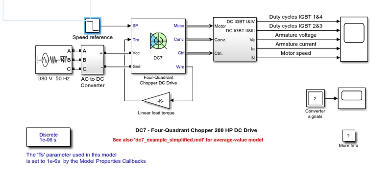
- In this model, the source is a 3 phase ac source.
- Then a rectifier is used to convert the ac to DC and Chopper is connected in order to stabilize the DC supply from the rectifier.
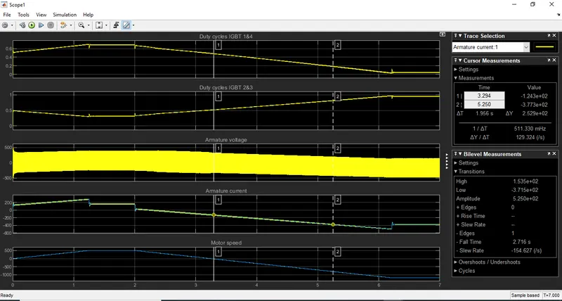
| BJT H-bridge | Four-Quadrant Chopper |
|
|
|
|
|
|
|
|
|
|
|
|
2. The objective is to develop a 2-quadrant chopper using Simulink & explain the working of the same with the relevant results.
- The 2-quadrant chopped is also called a C class chopper
- In this chopper, the voltage is positive and the current is either changed to positive or negative.
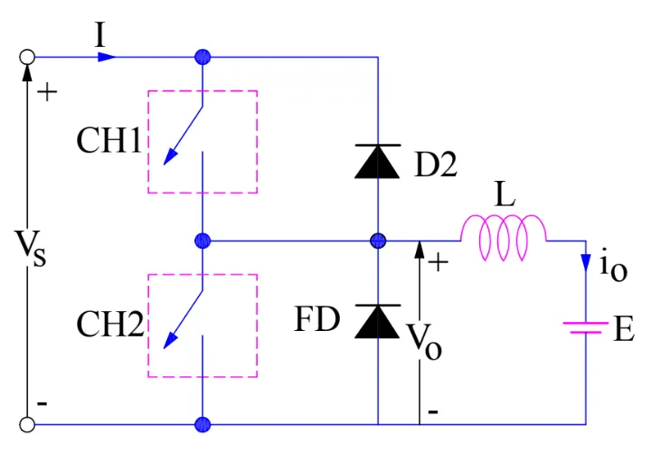
- When the CH1 is switched ON, the voltage flows through the inductor, during that period, the inductor stores some amount of energy.
- When the CH1 is switched off, the freewheeling diode conducts, and the polarity of the inductor changes by discharging the energy.
- Here, the voltage and current are positive.
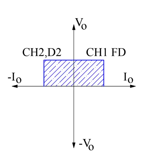
- When the CH2 is switched OFF, the direction of this current io will be opposite and voltage is positive.
- When CH2 is made OFF, diode D2 gets constructed and hence the current flows into the source from the load.
- Choppers CH1 and CH2 should not be ON simultaneously as this would lead to a direct short circuit on the supply lines.
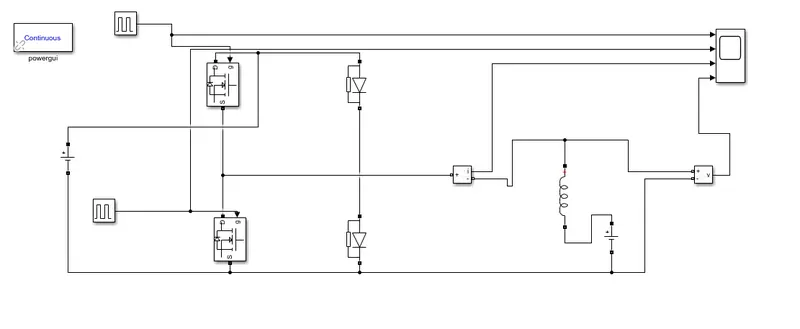
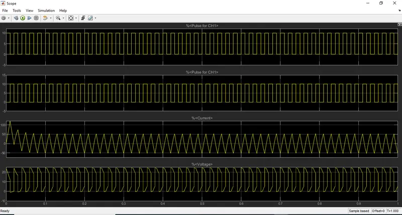
- For this model, the input supply is 250V, and load consists of 1mH inductance, 5Ω resistance, and 125 V battery.
- Two MOSFET switches CH1 and CH2 and used along with two diodes.
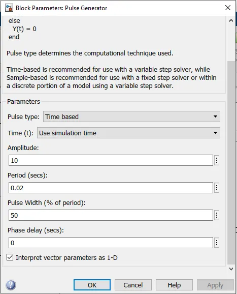
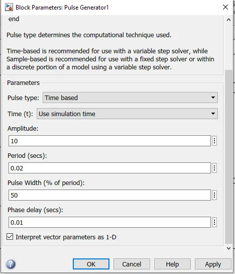
- The parameters set for the Gate Pulse blocks are as follows,
- G1: Amplitude - 10, period - 0.02s, pulse width - 50%, and phase delay - 0 s.
- G2:Amplitude - 10, period - 0.02s, pulsewidth - 50%, and phase delay - 0.01s.
- In this chopper. In this chopper when switch CH1 is on current flows from source to load and when switch CH2 is ON,
current flows from the load through switch CH2. - Thus load current can be positive or negative but load voltage remains positive.
- This chopper can be used for DC motor control and regenerative braking.
- When the output current is positive, the power delivered to the load is positive, and when the output current is negative, the power delivered to the load is negative.
- Switches CH1 and CH2 should not be turned on simultaneously as this would result in a short circuit of the input
supply.
3. The objective is to explain the operation of the BLDC motor.
- Brushless DC motor is a very popular motor type which is been using in several applications such as Automotive Industry, Industrial Automation, Transportation, and consumer appliances.
- As the name suggests, The motor doesn't have a brushed setup for commutation.
- The main design difference between brushed and brushless motors is the replacement of a mechanical commutator with an electric switch circuit.
- In this motor, the permanent magnets are attached to the rotor. The current-carrying conductors are located on the stator.
- A BLDC Motor is a type of synchronous motor in the sense that the magnetic field generated by the stator and the rotor revolve at the same frequency.
- The Lorentz force law states that whenever a current-carrying conductor is placed in a magnetic field it experiences a force.
- In the BLDC motor, the current-carrying conductor is stationary and the permanent magnet is moving.
- They are available n different standards such as single-phase, two-phase and three-phase.
- In these standards, three-phase BLDC motors are widely used.
- The connection is done in the star or Y connection.
- The pole may vary from 2 - 8 depending upon the requirements of and Application.
- Hall sensors or rotary encoders are most commonly used to sense the position of the rotor and are positioned around the stator.
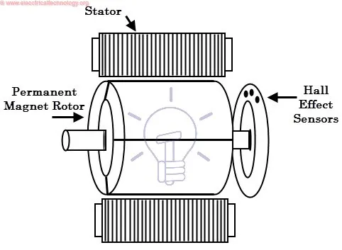
- The rotor position feedback from the sensor helps to determine when to switch the armature current
WORKING:
- When we supply the current to A coil, a magnetic field is generated and the rotor magnet is attracted. The position of the rotor is slightly turned clockwise and aligns with A-coil.
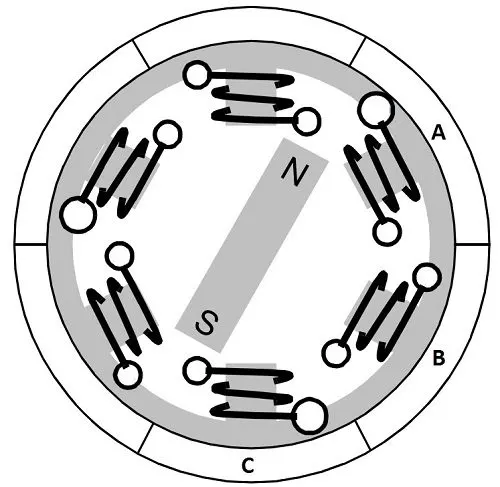
- Then, if we excite the B coil, then the rotor is attracted and turned clockwise and aligned to the B coil.
- By doing so, the rotor can be rotated in a clockwise direction.
- To increase efficiency, the coil can be wounded on opposite sides, which results in double attraction.
- For further efficiency, two coils can be excited at a time as one attracts and one repels. This can make a BLDC motor work efficiently.
Working with Brushless DC Motor Drive:
If stator and rotor are essential parts of a BLDC Motor that are integral to it, then the driving electronics are equally essential. A Block diagram of a typical Brushless DC Motor control or drive system is shown below,
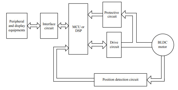
This drive circuitry is often known as Electronic Speed Controller System or simply an ESC. One common setup is called the Full-Bridge Drive Circuit. It consists of an MCU with PWM outputs, six MOSFET for the three phases of the stator windings, feedback from the Hall sensors, and some power supply-related components.
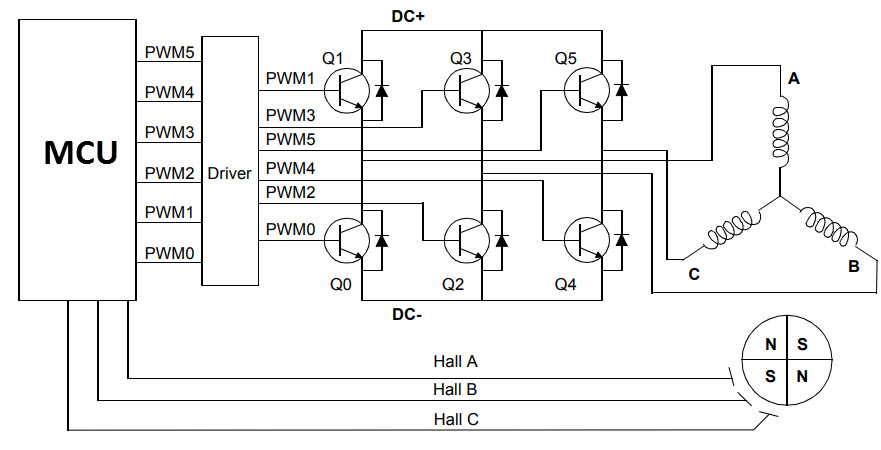
The MCU can be programmed to appropriately switch the MOSFETS based on the data from the Hall Sensors.
Advantages of Brushless DC motor:
- Less overall maintenance due to absence of brushes
- Reduced size with far superior thermal characteristics
- Higher speed range and lower electric noise generation.
- It has no mechanical commutator and associated problems
- High efficiency and high output power to size ratio due to the use of permanent magnet rotor
- High speed of operation even in loaded and unloaded conditions due to the absence of brushes that limits the speed
- Smaller motor geometry and lighter in weight than both brushed type DC and induction AC motors.
- Long-life as no inspection and maintenance is required for commutator system
- Higher dynamic response due to low inertia and carrying windings in the stator
- Less electromagnetic interference.
- Low noise due to absence of brushes.
Limitations of Brushless DC motor:
- These motors are costly
- The electronic controller required to control this motor is expensive
- Requires complex drive circuitry
- Need of additional sensors
Applications of Brushless DC motor:
Brushless DC motors (BLDC) use for a wide variety of application requirements such as varying loads, constant loads, and positioning applications in the fields of industrial control, automotive, aviation, automation systems, health care equipment, etc.
- Computer hard drives and DVD/CD players
- Electric vehicles, hybrid vehicles, and electric bicycles
- Industrial robots, CNC machine tools, and simple belt-driven systems
- Washing machines, compressors, and dryers
- Fans, pumps, and blowers.