Project
Objective:
The objective is to carry out a system-level simulation of an all-terrain vehicle and prepare a technical report explaining the model properties & comments on the results.
Observation:
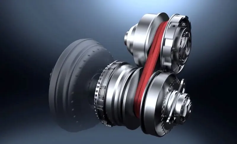
Firstly, the Continous Variable transmission (CVT) is one of the efficient gear transmission types which is efficient and used widely in the automobile sector. This transmission can optimize speed for different driving conditions ie.., it can deliver better acceleration on low speeds and better fuel economy on higher speeds. The construction of CVT is basically two pairs of curved pulleys in which one acts as a primary and the other one acts as a secondary pulley. Considering the pulley, one is fixed and the other open is movable with the help of a hydraulic cylinder. In between these two pulleys, a steel belt is connected to drive the pulley at lower and higher speeds with an efficient gear ratio.
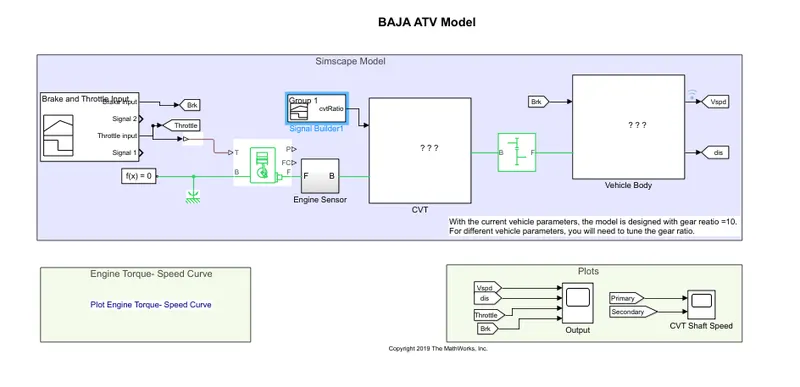
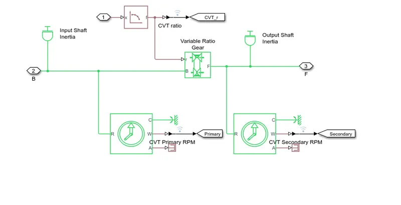
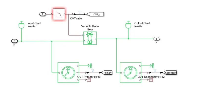
The CVT model used in the Simulink consists of a variable Gear ratio, Inertia Shaft, and an Ideal Rotational Motion Sensor. Let's deeply see each block,
- Variable Gear Ratio block represents a mechanical gearbox. The r port is the ratio of input and output shaft velocities.
- The B and F ports are the rotational ports in which one is connected to the input inertia shaft and the other one is connected to the output inertia shaft.
- The ideal rotational motion sensor represents the driven and driving pulley in the CVT gear transmission system.
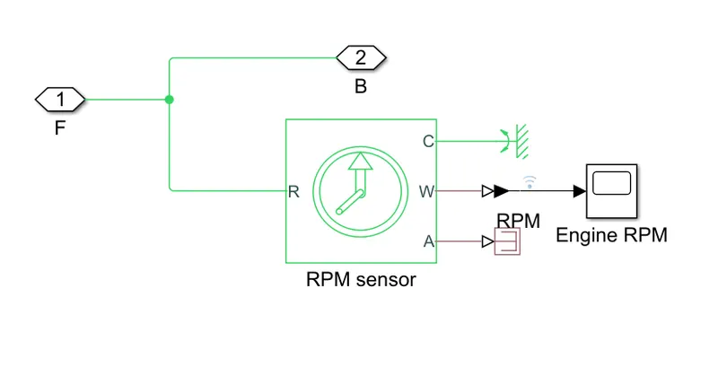
The Engine Sensor block consists of the RPM Sensor which is used to analyze and send the data of Engine RPM to the CVT block.
The Engine Block represents a mechanical engine used in vehicles. The B and F ports are normally rotational ports. The P and FC ports are the ones in which the engine power and fuel economy can be obtained.
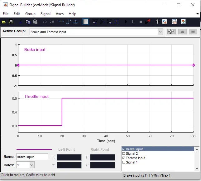
The input signal to the Engine Block is fed via Signal Builder which generates signals for throttle and Brake.
A Mechanical Rotational Reference and a solver configuration are connected to the Engine block.
A simple gear block is connected with CVT block t feed the value and B and F ratio and the direction to rotate.
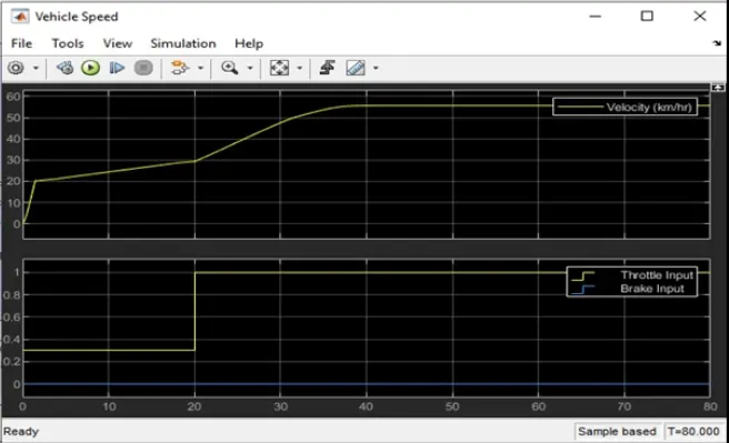
The throttle input is given as 0.3 for 0 to 20 sec and 0.5 for 20sec to 80 sec when the brake input is given as 0.
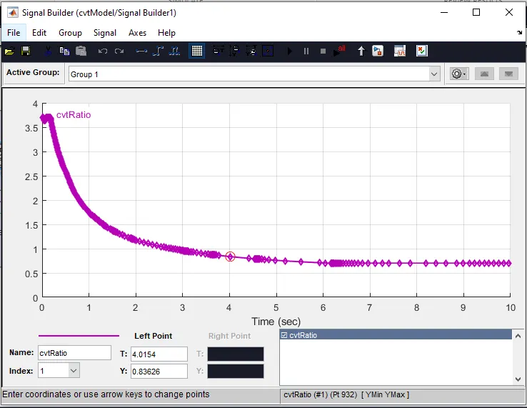
CVT Ratio Output
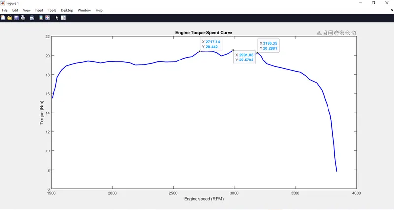
Engine Torque Speed-Torque Curve
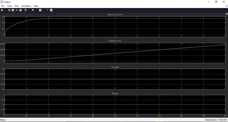
Velocity and Distance curve
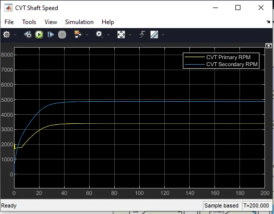
CVT Shaft Speed (Primary and Secondary)
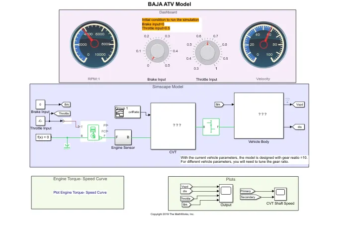
BAJA ATV WITH DASHBOARD MODEL
In this model, the input for the Throttle and brake is fed via the knob component and displayed with RPM and Velocity meter. By increasing the throttle input, the velocity and engine RPM increase, and a gear ratio is maintained according to the engine speed. Whenever the brake input is applied from 0 to 0.5, the velocity gradually decreases to zero.
BAJA ATV WITH CVT USING LOOKUP TABLE
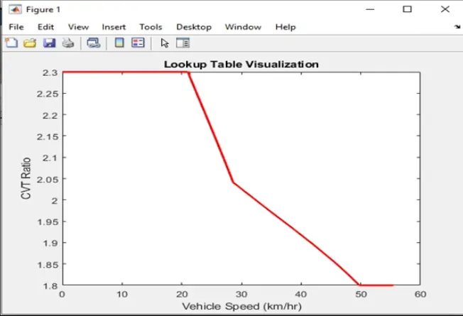
The components and subsystems used in this model are the same as the before models but the difference is that input to the gear ratio is fed through the lookup table.
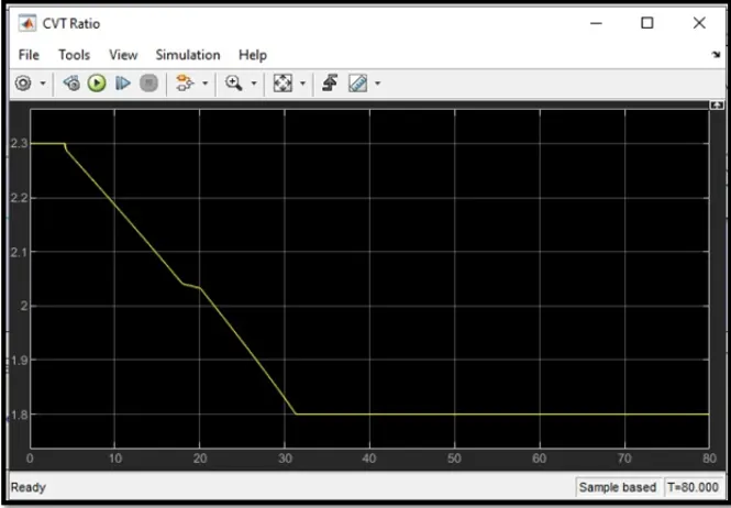
CVT Gear Ratio
Lookup Table Visuliazation
Vehicle Speed
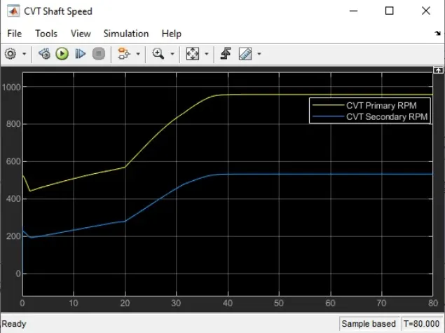
CVT Shaft RPM
Result
Thus, by observing and implementing 4 models of CVT we have changed the Gear ratio, Engine Speed, Velocity, etc.., with the help of throttle and brake input.