Week -2
1. The objective is to design a Simulink model of the doorbell using a solenoid block with the respective conditions. Firstly, the condition was to create a condition in which the switch is closed for 2 seconds.
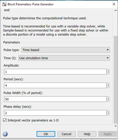
- To achieve this, a pulse generator was included and a phase delay of 2 sec was fed as input which generated a square wave signal at regular intervals.
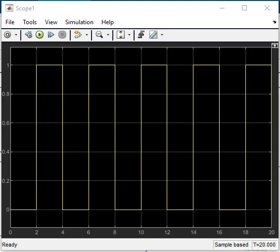
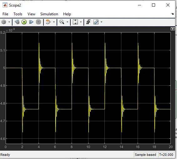
The result of the pulse generator is given below,
- Then, coming to Simulink Diagram, The pulse generator was connected to the switch via Simulink PS converter, and the whole primary switch circuit was powered by a Battery Source.
- A solver configuration was connected to the electrical reference line since the Simulink consists of some mathematical calculations performed using Simulink blocks.
- The Solenoid block is connected to the battery and switch and a translational Motion Sensor is connected with the Solenoid represents a doorbell's metal arm.
- The R port of the Motion Sensor is connected to Solenoid and the C port is connected to the Mechanical reference.
- Scope and Display is connected to Translational Motion Sensor to obtain the desired output.
- PS Simulink block is used to convert the physical signal to a Simulink signal.
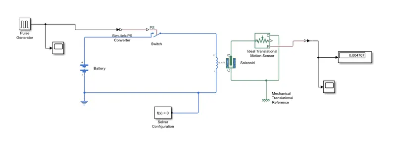
- Finally, the metal arm contacts the hanger, and the doorbell activates every 2 seconds in the given time interval.
2. The objective is to use a thermistor to sense the temperature of a heater & turn on or turn off the fan and to satisfy the given conditions,
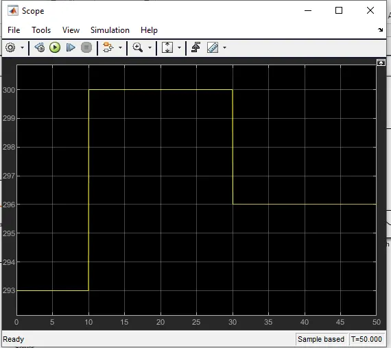
- A Signal Builder is included in order to give the inputs as,
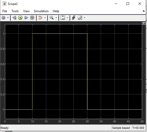
- 20 °C from 0 to 10 seconds ie.., 293K
- 27 °C from 10 to 30 seconds ie..,300K
- 23 °C from 30 to 50 seconds ie..,296K
- The Fan must be turned ON when the temperature is above 25 C.
- The Fan must be turned OFF when the temperature is below 25 C.
- Controlled Temperature Source was connected to Signal Builder with a thermal Reference to maintain a controlled temperature difference
- The S port was connected to Signal builder via Simulink PS which is used to convert the Simulink signal to physical Signal
- The A port is connected to the thermal reference
- The b port is connected to the Thermistor
- The whole circuit is powered by a battery source which is connected with an electrical reference
- A resistor is connected with Voltage Sensor to the circuit which can measure the voltage produced during regular intervals
- Then a Switch is connected to the voltage sensor and then the output is obtained from the switch via scope
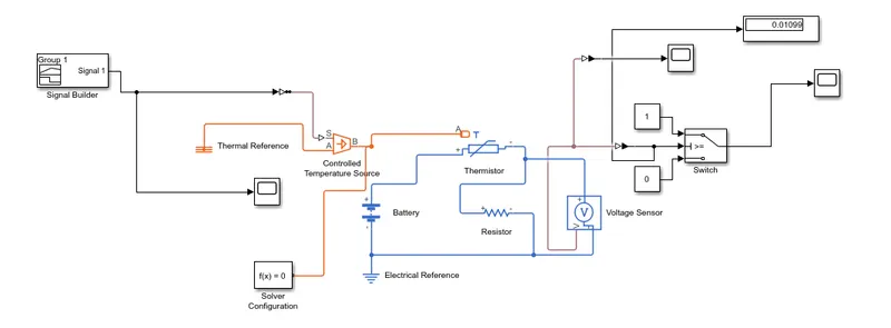
- In observation, a voltage of 0.01099V was produced at the temperature of 25 C so the threshold voltage range ops switch is given with this range.