Week-7 Challenge: DC Motor Control
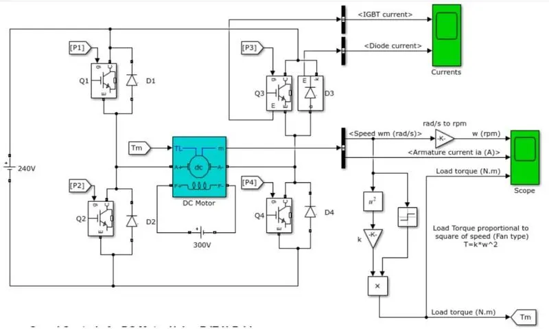
1. A. Explain a MATLAB demo model named ‘Speed control of a DC motor using BJT H-bridge’.
B. Comment on the armature current shoot-up from the scope results.
C. Refer to the help section of ‘The Four-Quadrant Chopper DC Drive (DC7) block’. Compare it with the H-bridge model.
A)
What is DC motor?
A direct current machine is one that converts electrical energy into mechanical energy and vice versa. Forward motoring is the conversion of electrical energy into mechanical energy, while regenerative braking is the conversion of mechanical energy into electrical energy. A DC drive circuit is required to operate a DC machine as both a generator and a motor. The BJT H bridge drive is used in this model. Because of the use of BJT switches,these motor cannot operated for braking. This drive model used for Forward motoring and reverse motoring.
What is BJT ?
A bipolar junction transistor (BJT) is a three-terminal semiconductor system. The term "bipolar" refers to the fact that this type of transistor comprises two types of semiconductor material, one positive (p-type) and one negative (n-type), through which current flows.Silicon is commonly used in bipolar junction transistors. Furthermore, impurities are often applied to silicon by doping to make the layers behave as desired.
It is the role of the p-type layers in a BJT to attract electrons that reach the transistor through its input circuit. In contrast, the n-type layers should allow electrons to flow out of the transistor.The push-and-pull effect between the layers amplifies and controls the electrical current.
The structure of the layers in a BJT controls the flow of electrical current and ensures that a charge cannot return in the same direction from which it originated. This configuration keeps the machine from overheating or being damaged.
BJTs are created by layering p-type and n-type silicon to form a three-layer “sandwich”:
BASE : The base, to which a small starting current is linked.
EMITTER : The emitter is the device that emits electrons.
COLLECTOR : The collector is the device that absorbs the amplified electrons. Electrons are transferred between the emitter and the base.
Then bipolar transistors have the ability to operate within three different regions:
Active Region – the transistor operates as an amplifier and Ic = β*Ib
Saturation – the transistor is “Fully-ON” operating as a switch and Ic = I(saturation)
Cut-off – the transistor is “Fully-OFF” operating as a switch and Ic = 0
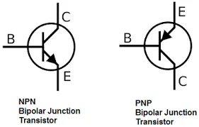
Bioplar junction transistor are classified into two types: NPN (negative-positive-negative) and PNP (positive-positive-positive) (positive-negative-positive). The former is activated when current flows through the base, while the latter is activated only when there is no current flowing through the base.
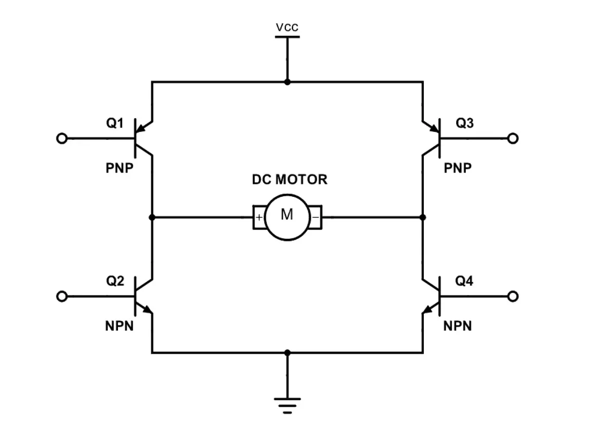
BJT H- Bridge
An H-bridge is a transistor arrangement that gives a circuit complete power over a regular electric DC motor. In other words, an H-bridge enables a microcontroller, logic chip, or remote control to electronically control the motor's forward, reverse, brake, and coast functions.
The H-bridge is made up of four BJT/Diode pairs (BJT simulated by IGBT models). Q1 and Q4 or Q2 and Q3 transistors are switched at the same time. When Q1 and Q4 are turned on, a positive voltage is applied to the motor, and when Q1 and Q4 are turned off, diodes D2-D3 act as free-wheeling diodes. A negative voltage is applied to the motor when Q2 and Q3 are shot.and diodes D1-D4 operate as free-wheeling diodes when Q2 and Q3 are switched off.
Pulse Generator:
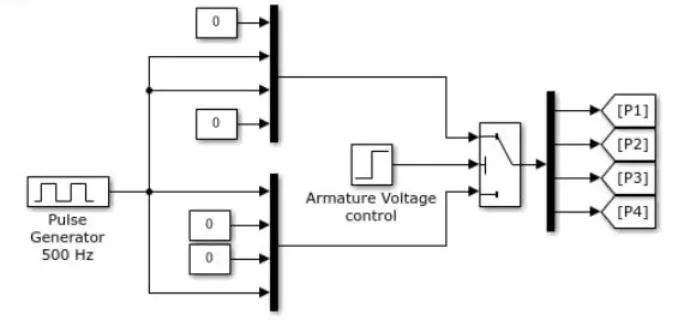
The pulses for BJT are produced using a pulse generator. Pulses of a certain frequency are encoded using two 4*1 encoders, as shown above. The voltage from the decoder and armature is applied to the operated switch.
One 14-bit decoder is fed from a controlled switch. Using the goto block, pulses from this decoder are routed to the appropriate BJTs. If the aramature voltage is greater than 2 seconds, the top encoder is selected, Q3 and Q2 are triggered, and the motor operates in reverse. If the aramature voltage is less than 2 seconds, the phase time is reducedthe bottom encoder will be selected and Q1 and Q4 will be Triggered and motor will opearte in Forward direction.
B)
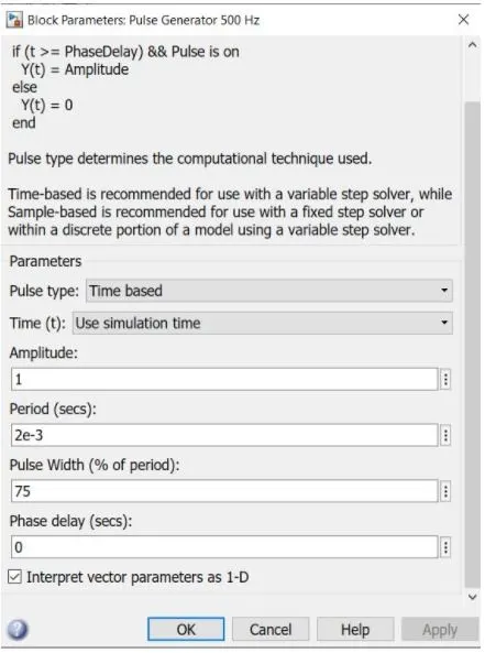
The default duty cycle is 75%
we can see the output result
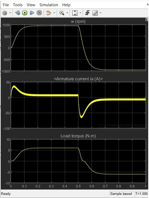
The defined cycle has a service cycle of 75%, which means that the software is on for 75% of the time and off for 25% of the time.We can see from the plot that for Q3 and Q4, the input is given after 0.5 sec, implying that the IGBT signal is present after 0.5 sec to 1 sec.In the first loop, we can see that the diode current passes, indicating that current passes through the circuit, and after 0.5 sec, there is no diode current, indicating that no current passes through the circuit or that the current passes in the opposite direction. We can see from the plot that the motor took about 0.1 second to reach its full rated speed, which is due to the load applied.In Q3 mode, the motor begins to slow down or reverse and reaches a maximum speed of -1000 rpm.
The armature current overshoots as it switches direction due to the applied load and then returns to its constant current supply due to constant speed.
Reducing the armature current shoot up when changes the current direction
We can reduce the increase in motor current while shifting direction by lowering the duty cycle to 50%.
we can see the result:
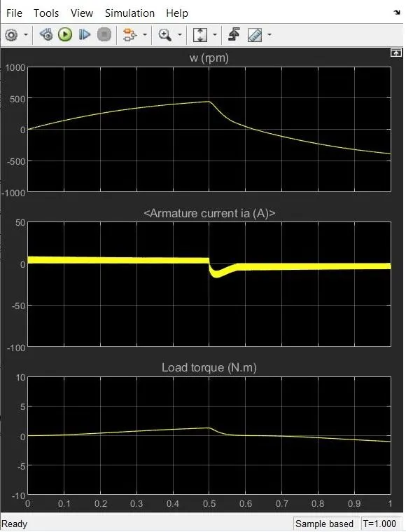
We can see that by reducing the service cycle to 50%, the armature current shoot up when changing direction is decreased.
C)
The Four-Quadrant Chopper DC Drive (DC7) block’.
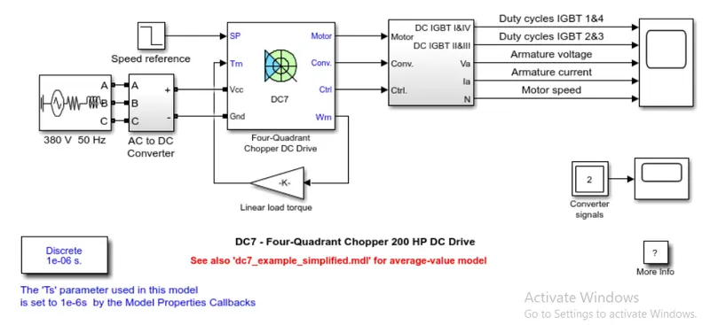
The four-quadrant DC drive, blocks reflect a four-quadrant, DC-supplied chopper drive for a DC motor. The drive has closed-loop speed control and four-quadrant operation. The machine's reference armature current is output by the speed control loop.
The chopper duty cycle corresponding to the commanded armature current is calculated using a PI current controller. This duty cycle is then compared to the sawtooth carrier signal to generate the PWM signals required by the chopper.
The chopper transforms a fixed DC voltage into a variable DC voltage. Self-commutated (directly on or off devices through a gate) devices such as MOSFETs, IGBTs, power transistors, GTOs, and IGCTs are used in choppers because they can be commutated by a low power control signal and do not need a commutation circuit.
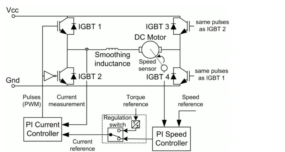
The H-Bridge block represents an H-bridge motor driver. The block has the following two Simulation mode options:
PWM — The H-Bridge block output is a controlled voltage that depends on the input signal at the PWM port. If the input signal has a value greater than the Enable threshold voltage parameter value, the H-Bridge block output is on and has a value equal to the value of the Output voltage amplitude parameter. If it has a value less than the Enable threshold voltage parameter value,
| Slno | Four-Quadrant Chopper DC Drive (DC7) block | H-bridge model |
| 1 |
Typically used in the automotive industry to regulate the speed and direction of DC motors. |
It is commonly used in robotics and electromechanical devices to regulate the speed and direction of DC motors. |
| 2 |
In the DC7, regenerative braking is possible. |
Only dynamic braking is possible. |
| 3 |
It is capable of operating in all four quadrants of DC motors. |
It can only move in forward and reverse directions. |
| 4 |
Only DC-DC converters with high switching frequencies are feasible. |
It shows the simulation value in precise mode. |
| 5 |
It has a greater torque and output power range. |
It has a limited torque and power output. |
2. Develop a 2-quadrant chopper using simulink & explain the working of the same with the relevant results. (Refer to article - Multiquadrant operation of motor )
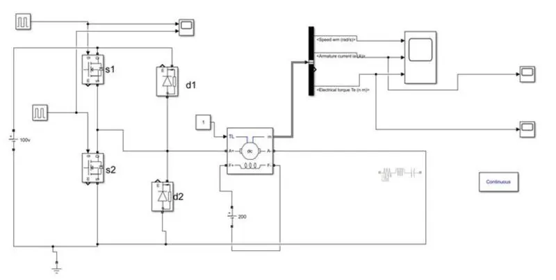
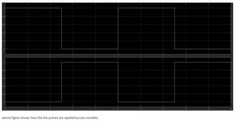
A DC supply is used in conjunction with a DC drive to power a DC motor. DC drive is nothing more than a two-quadrant chopper made up of two mofets and two diodes connected as shown above. Mosfet drive activity is triggered by pulse generators. A constant block is used to apply a torque of 1Nm to a DC machine.
Working:
1st quadrant operation
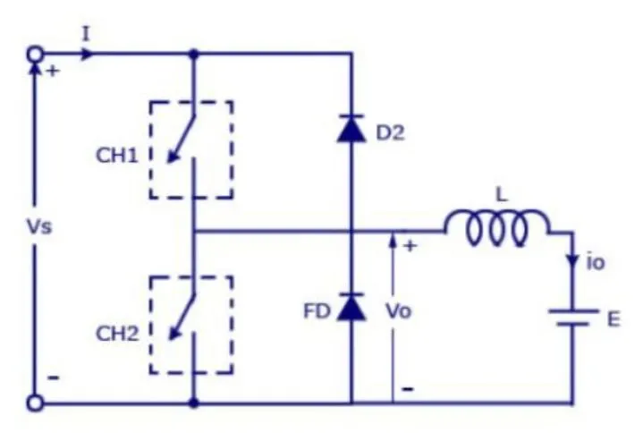
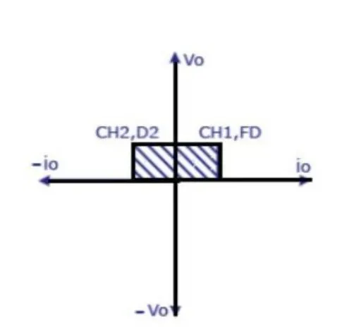
When s1 is turned on and s2 is turned off, positive vdc is applied around the motor. Voltage and current are both positive at this time.The motor will turn in the forward direction.
2nd quadrant operation
When s2 is turned on and s1 is turned off, the voltage around the motor is positive, but the aramature current is negative.It is operating in forward regeneration mode.
Pulse generator Signal:
Result:
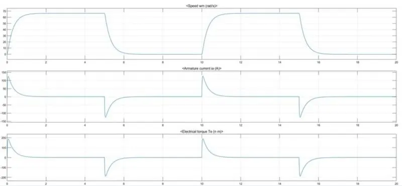
S1 is turned on for 5 seconds, during which time the motor rotates forward. The speed is 60 rads/s, the aramture current is approximately 0.8 amps, and the load torque is 1Nm.
A two-quadrant chopper for a direct current motor that can be used for both forward motion and forward braking has been developed. At the start of Aramature, the peak current value is nearly 120A. This peak current has the potential to damage the windings. A starter is used to reduce the starting current.
3. Explain in a brief about operation of BLDC motor.
What is Brushless DC motor?
Brushless direct current electric motors, also known as electronically commutated motors, are a type of DC electric motor (ECMs, EC motors). Primary performance is a critical function of BLDC motors. Since the rotor is the sole magnet bearer and does not need any fuel.
That is, there are no connections, no commutator, and no brushes. Instead, the motor makes use of control circuitry. BLDC motors use controls, rotary encoders, or a Hall sensor to detect where the rotor is at any given time.
Construction of Brushless DC motor
Permanent magnets are attached to the rotor in this motor. The current-carrying conductors, also known as armature windings, are found on the stator. Electrical commutation is used to transform electrical energy into mechanical energy.The primary design distinction between brushed and brushless motors is the substitution of an electric transfer circuit for the mechanical commutator. A BLDC motor is a type of synchronous motor because the magnetic fields produced by the stator and rotor revolve at the same frequency.
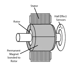
There are no current carrying commutators in a brushless motor. The field within a brushless motor is switched by an amplifier that is activated by a commutating device such as an optical encoder.
A DC brushless motor's layout will differ depending on whether it is in "Out runner" or "Inrunner" mode.
OUTRUNNER- The field magnet is a rotating drum rotor that revolves around the stator. This style is chosen for applications that need high torque but do not require high rpm.
INRUNNER- The stator is a fixed drum that houses the field magnet. This motor is notorious for generating less torque than outrunner motors, but it can spin at extremely high rpm.
Working Principle of Brushless DC motor
A BLDC motor operates on the same principle as a Brushed DC motor. The Lorentz force law states that a current carrying conductor feels a force if it is put in a magnetic field. The magnet can feel an equal and opposite force as a result of the reaction force. The current carrying conductor is stationary in the BLDC motor, while the permanent magnet is going.
As the stator coils receive power from the source, they become electromagnets and begin to produce a uniform field in the air gap. Despite the fact that the power source is DC, switching produces an AC voltage waveform with a trapezoidal shape. The rotor continues to spin due to the force of interaction between the electromagnet stator and the permanent magnet rotor.
Windings are switched as High and Low signals, and the corresponding windings are energised as North and South poles. The motor rotates because the permanent magnet rotor's North and South poles correspond with the stator poles.
Advantages of Brushless DC motor
- Less overall maintenance due to absence of brushes
- Reduced size with far superior thermal characteristics
- Higher speed range and lower electric noise generation.
- It has no mechanical commutator and associated problems
- High efficiency and high output power to size ratio due to the use of permanent magnet rotor
- High speed of operation even in loaded and unloaded conditions due to the absence of brushes that limits the speed
- Smaller motor geometry and lighter in weight than both brushed type DC and induction AC motors.
- Long life as no inspection and maintenance is required for commutator system
- Higher dynamic response due to low inertia and carrying windings in the stator
- Less electromagnetic interference
- Low noise due to absence of brushes
Limitations of Brushless DC motor
- These motors are costly
- Electronic controller required control this motor is expensive
- Requires complex drive circuitry
- Need of additional sensors
Applications of Brushless DC motor
Brushless direct current (BLDC) motors are used for a wide range of application requirements such as varying loads, constant loads, and positioning applications in the fields of industrial control, automobile, aviation, automation systems, health care equipment, and so on.
- DVD/CD players and computer hard drives
- Electric cars, hybrid vehicles, and electric bicycles are all options.
- Industrial robots, CNC machine machines, and basic belt-driven systems are examples of such systems.
- Machines for washing clothes, compressors, and dryers,Fans, motors, and blowers are all examples of mechanical devices.