Project
Baja all-terrain vehicle stimulation using simulink
AIM: To test a system-level simulation of a Baja all-terrain vehicle using simulink and to evaluate the results.
ALL TERRAIN VEHICLE
An all-terrain vehicle (ATV), also known as a light utility vehicle (LUV), is a vehicle that runs on low-pressure tyres and has a bench that the user straddles as well as handlebars for steering power. It is designed to tackle a broader range of terrain than most other vehicles,
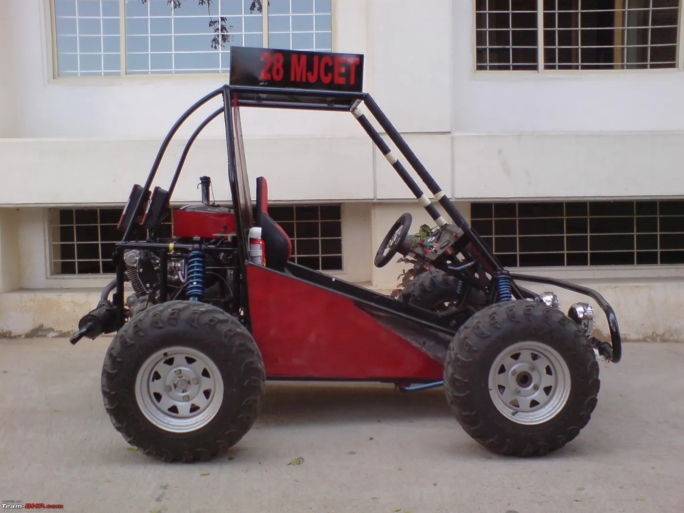
as the name suggests. ATVs are designed to be controlled by a single person.The rider sits on and controls these vehicles similarly to a car, but the extra wheels provide greater stability at slower speeds. Despite the fact that the majority have three or four wheels,
the above showned all terrain vehicle is used in the competion of baja
MAIN SYSTEM
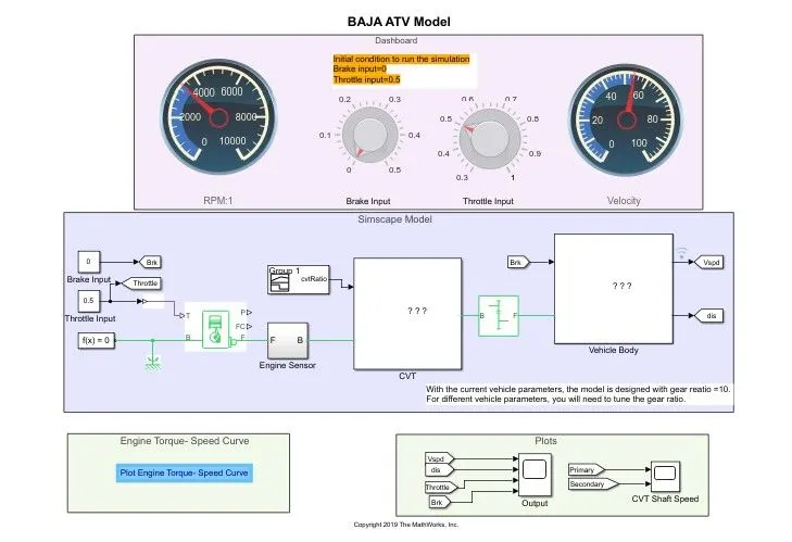
This is the main system of the Baja all-terrain vehicle model, and it consists of many components, including a vehicle body, continuously variable transmission (CVT), engine parts, and an engine sensor. There are many components in the cvt and vehicle body that we can see in subsystems. There are two inputs in this section: throttle and brake.
In the output section, we can see how far the vehicle has travelled, its velocity, and the cvt primary and secondary rpm.these all we can figure out by the ouput section
so we can check the subsystems
VEHICLE BODY
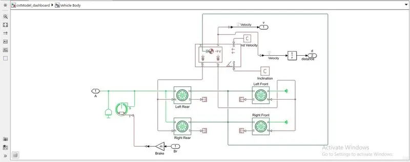
This is the parts within the vehicle body subsystem, in which we can see the vehicle's wheels, its double shoe brake, and the inclination of the body interior. In this subsystem, we are providing all of the vehicle model's values.
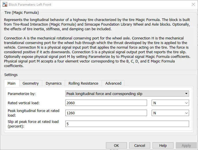
This block parameter shows how much vertical load and longitudinal force are acting on this vehicle's tyre. We may add force to the tyres by testing the load and force.Like this Any pressure acting on a vehicle's body is checked and stored in the vehicle's body subsystem.
BLOCK USED
TIRE

The Tires and Vehicles library allows you to test the response of your driveline model under a variety of changing environmental conditions.
VEHICLE BODY
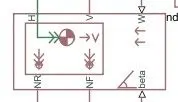
The Vehicle Body block lets you model only longitudinal dynamics, parallel to the ground and oriented along the direction of motion. The vehicle is assumed to be in pitch and normal equilibrium. The block does not model pitch or vertical movement.
DOUBLE SHOE BRAKE
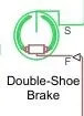
The Double-Shoe Brake block represents a frictional brake composed of two pivoted rigid shoes that push against a rotating drum to produce braking action. In applications such as motor vehicles and some heavy equipment, double-shoe brakes provide high braking torque with limited actuator deflections.
CONTINUOUSLY VARIABLE TRANSMISSION (CVT)
Continuous variable transmissions, unlike conventional automatic transmissions, ignore a gearbox with a fixed number of gears, which means they avoid interlocking toothed wheels. The most popular form of CVT is based on a clever pulley system that allows infinite variability between highest and lowest gears with no distinct steps or changes.
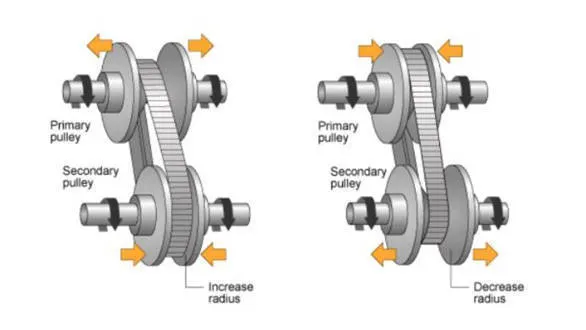
A gear is a ratio of engine shaft to driveshaft speed. While CVT adjust this ratio without the use of planetary gears, for the sake of tradition, they are still referred to as having low and high "gears."
The variable-diameter pulleys are the heart of a CVT. Each pulley is made of two 20-degree cones facing each other. A belt rides in the groove between the two cones. V-belts are preferred if the belt is made of rubber. V-belts get their name from the fact that the belts bear a V-shaped cross section, which increases the frictional grip of the belt.
When the pulley's two cones are far apart the belt rides lower in the groove and the radius of the belt loop moving around the pulley shrinks. As the cones are close together, the belt rides higher in the groove and the radius of the belt loop around the pulley increases. CVTs can make use of hydraulic pressure.
Variable-diameter pulleys must always be sold in sets of two. One of the pulleys, known as the drive pulley (or driving pulley), is attached to the engine's crankshaft. The driving pulley is also known as the input pulley because it is where the engine's energy reaches the transmission. Since the first pulley is turning it, the second pulley is known as the guided pulley.As an output pulley, the driven pulley transfers energy to the driveshaft.
To hold the belt close, as one pulley raises its radius, the other decreases its radius. As the radii of the two pulleys shift relative to one another, they generate an infinite number of gear ratios ranging from low to high and all in between. When the pitch radius on the driving pulley is small and the pitch radius on the driven pulley is high, the rotational speed of the driven pulley decreases.As a consequence, the "gear" is smaller. When the pitch radius on the driving pulley is wide and the pitch radius on the driven pulley is small, the rotational speed of the driven pulley increases, resulting in a higher "gear." Thus, a CVT has an infinite number of "gears" that it can cycle through at any time, regardless of engine or vehicle speed.
CVT SUBSYSTEM
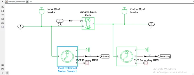
Inside a cvt subsystem there are several parts are there
BLOCK USED
IDEAL ROTATIONAL MOTION SENSOR
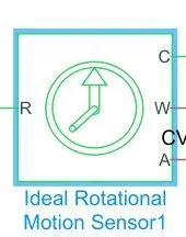
The Ideal Rotational Motion Sensor block represents an ideal mechanical rotational motion sensor, that is, a system that transforms an across variable measured between two mechanical rotational nodes into an angular velocity or angle proportional control signal.
VARIABLE RATIO GEAR
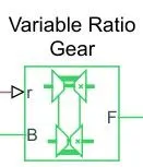
The Variable Ratio Transmission block represents a gearbox that transfers motion and torque between the two related driveshaft axes, base and follower, dynamically. Ignoring transmission compliance dynamics, the driveshafts are forced to corotate with a variable gear ratio that you control.
PS TERMINATOR
PS Terminator blocks are used to cap physical signal output ports that are not connected to other blocks. Unconnected physical signal output ports do not produce alerts, unlike conserving ports in physical modelling or Simulink output ports.
ENGINE SENSOR
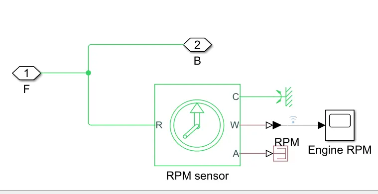
This is the engine sensor subsystem, and there is a sensor in here that is used to detect the engine's rpm. The block used is an ideal rotational motion sensor block, from which the engine's rpm is sensed.
These are the three subsystems of the main system, which are the vehicle body, the continuously variable transmission, and the engine sensor.
The input signal gives to the CVT through the signal builder
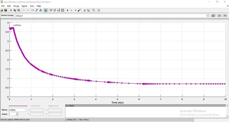
This is the input signal that we are feeding into the CVT, and we can see that at the beginning, the cv ratio is 3.7, but as time passes, it begins to decrease and eventually reaches a straight line, at which point the value becomes 0.7. The cv ratio is decreased from time 0 to 4 seconds and then becomes constant.
* we can check the process of ATV model by giving input
* Brake input : 0
* Throttle input : 0.5
Main system
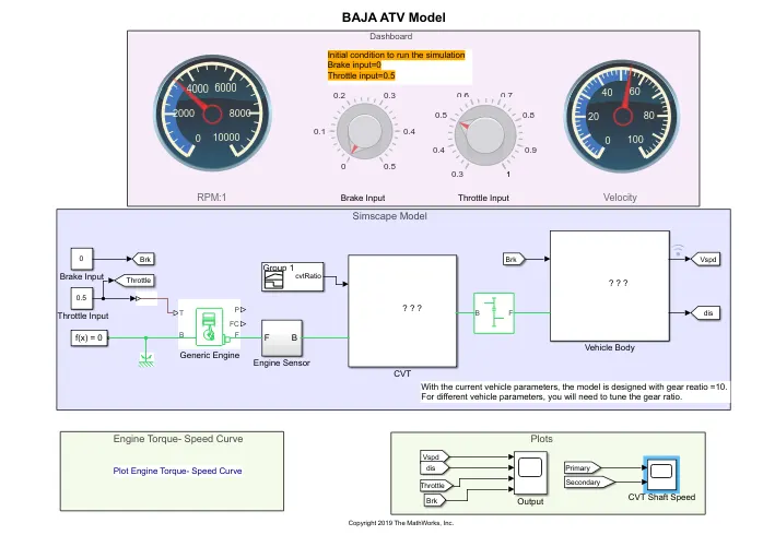
If we give the inputs Brake input: 0 and Throttle input: 0.5, the output will be
OUTPUT SIGNAL
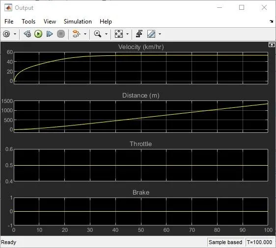
This is the output signal that we get after stimulation. We can see that the brake and throttle values showned as per we given input that is brake is : 0 and the throttle is : 0.5, as per the output signal we can conclude that at the time 0 to 100 seconds the vehicle moves nearlly 1500 m and the velocity value at the time 0 to 30 sec the velocity increases and attains a constant value from time 30 s to 100 s
CVT shaft speed
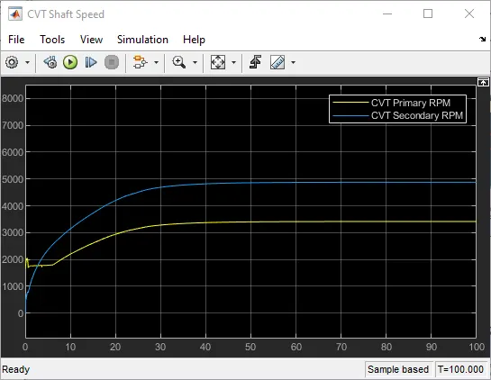
This graph depicts the cvt primary and secondary rpm values with respect to time. The primary cvt rpm starts at 1750 when the time is zero. And then, at the start, the signal fluctuates from 1750 to 2050 again it comes down. If the time is up to 5 seconds, the signal is between 1750 and 1800.as shown in the below graph it is showing
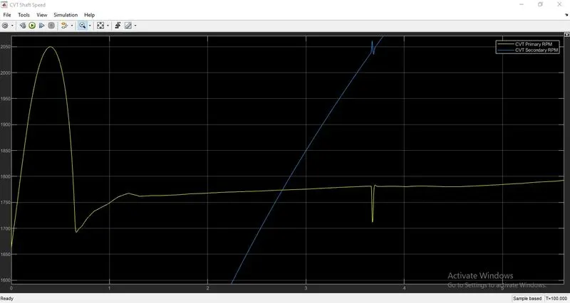
After that, the signal increases up to 30 seconds and reaches a steady position near 3400. It then becomes constant and travels from 30 to 100 seconds.
If we check the secondary cvt RPM then
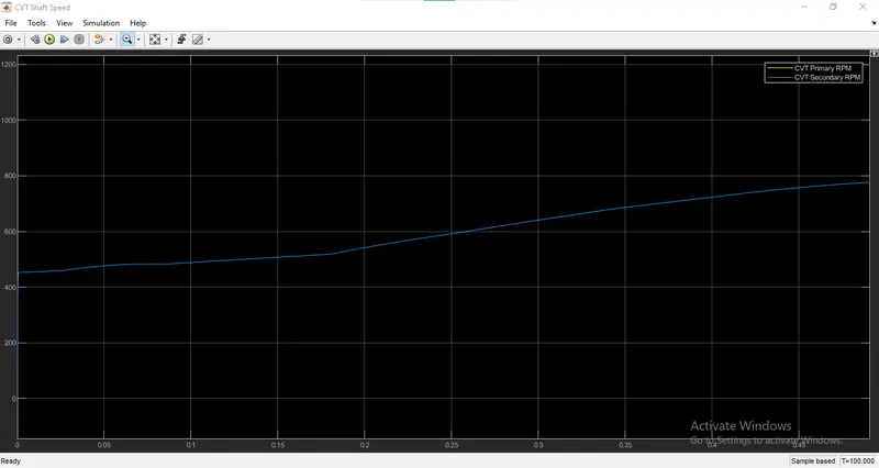
The graph clearly shows that it begins from o and then suddenly increases to more than 400 at the 0 time, then increases from 400 to 800 and then suddenly increases the values to the time 30 seconds. The secondary signal boosts the signal for 30 seconds, after which the value stabilises at around 4900. the value rises until it reaches a constant value
ENGINE TORQUE SPEED CURVE
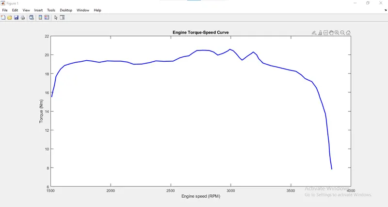
This is the torque speed curve for the engine. This graph is plotted between torque and engine speed, so that at 1500 RPM engine speed, the torque generated by the engine is greater than 15, and then it begins to increase between 18 and 20 at rpm 1700, and from there to nearly 3000 rpm speed, the torque fluctuates between 18 and 20. Then there is a high fluctuation that occurs after that and it begins to decreases like 3300 rpm and up to 3800 nearlly the torque decreased to value 8.This is the process occured in the engine torque speed curve.
* We can check the process of ATV by giving input
* Brake input : 0.3
* Throttle input : 0.5
MAIN SYSTEM
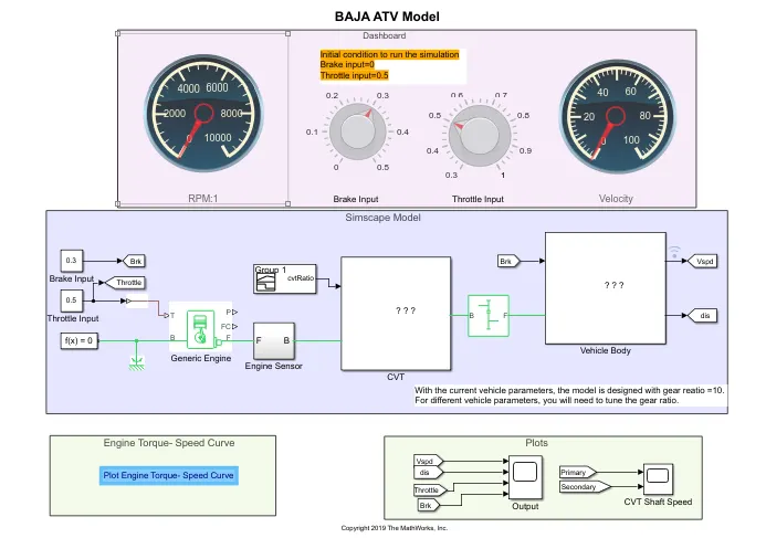
If we give the inputs Brake input: 0.3 and Throttle input: 0.5, the output will be
OUTPUT SIGNAL
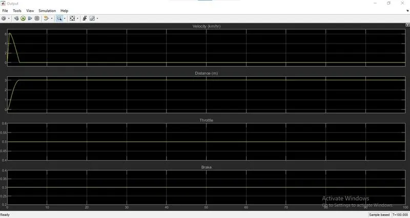
This is the output signal that we get after the stimulus in here the input that we are given is Brake input is : 0.3 and Throttle input is : 0.5 and then we can see up to 3 m the vehicle travels and then it stops because the brake is applied in it.
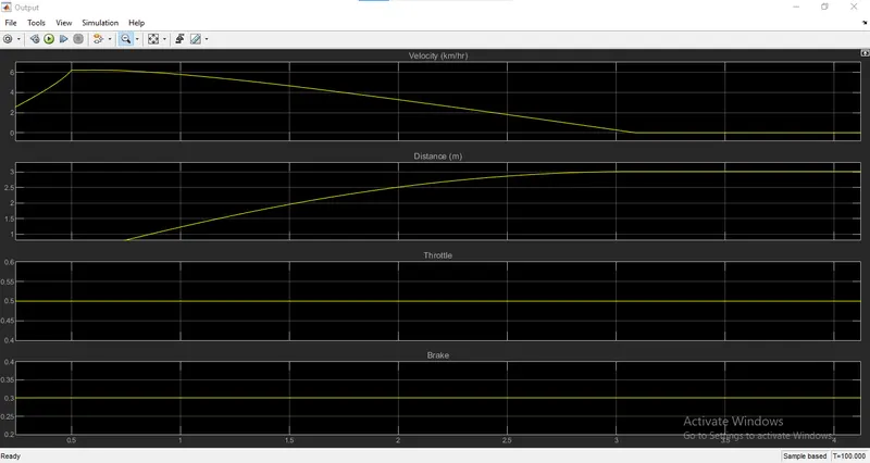
In the velocity graph, we can see that at the beginning, it rises from 2 to 6 from tom 0 to 0.5, then it begins to decrease up to time 3 sec, at which point the velocity becomes zero. We can then assume that we are using throttle 0.5 and brake 03, so that at the beginning, the vehicle travels to 3 metres and then stops, and the velocity then becomes zero.
CVT shaft speed
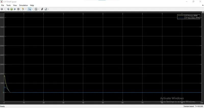
This is the CVT shaft speed graph, and it shows that when the signals are turned on, the CVT primary and secondary RPM fluctuate at first, then begin to decrease. The vehicle starts, then the brake is applied, and the vehicle comes to a stop.
we can closely lookup the graph
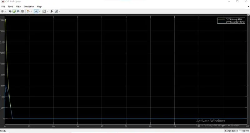
In this case, both the primary and secondary rpms suddenly increase, then decrease and return to zero after 3 seconds.
When we applied brake 0.3 and throttle 0.5, the vehicle moved up to 3 metres, then braked, and eventually vehicle stop.
* We can check the process of ATV by giving input
* Brake input : 0
* Throttle input : 0.56
MAIN SYSTEM
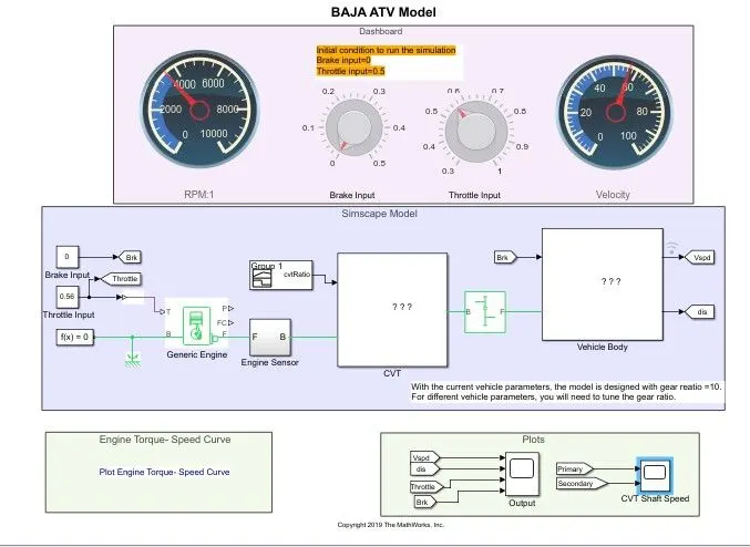
If we give the inputs Brake input: 0 and Throttle input: 0.56, the output will be
OUTPUT SIGNAL
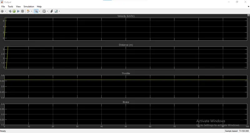
This is the output signal that we get when we apply the input brake : 0 and the throttle :0.56 in here we can see that the vehicle is moving and the speed is rising the velocity is also increasing at a certain second it go on increasing.
CVT shaft speed
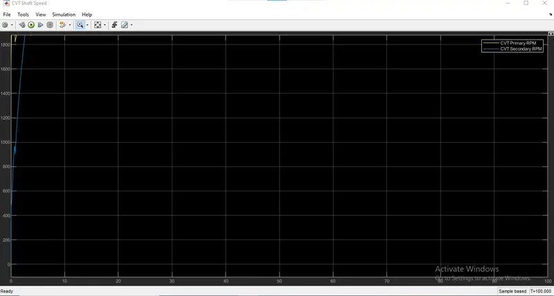
This is the CVT shaft speed graph, and we've set the brake to 0 and the throttle to 0.56, so the vehicle is still running and the speed is rising as the cvt primary and secondary rpm also rising
CONCLUSION
We checked all the blocks in this stimulation and seen all the subsystems.
We tested the all terrain vehicle stimulus under three different conditions, starting with the default condition and then changing the brake value and checking the output. Finally, we inserted the brake as the default value and adjusted the speed and checked the output.