Week -2
1) Simulink model of Doorbell using solenoid block
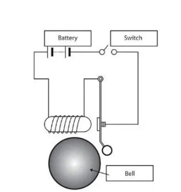
DESCRIPTION :
We will create a Simulink model of a doorbell using a solenoid block. When we apply an input current to the solenoid, it acts as a magnet and pulls the metal arm to strike the bell, producing sound. And the input is given as a time interval of 2 seconds.
We are going to do this process by using simulink
SOLENOID
A solenoid is an electromagnet that produces a balanced magnetic field by winding a coil into a tightly packed helix. As an electric current is passed through the coil, it can be set up to generate a uniform magnetic field in a volume of space.
MAIN SYSTEM
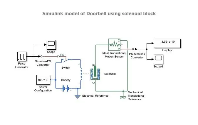
The metal arm is pushed by a solenoid to strike the bell and create sound, as seen in the main system above. We are connecting a switch and a battery to operate solenoid as a magnet.
Using a pulse generator, we must send pulse signals to the switch. We must Create a situation where the switch is closed for 2 seconds and then released . As a result, we must adjust the pulse generator's values.
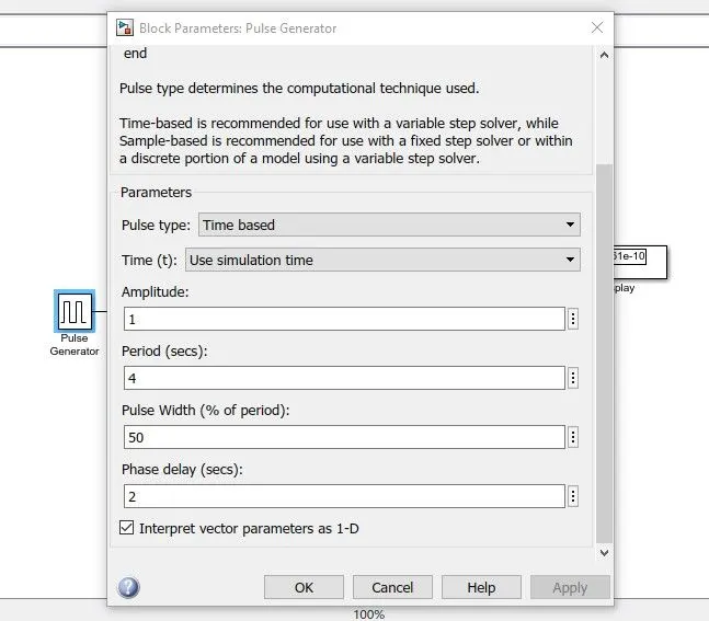
When the pulse generator phase delay is set to 2 seconds, the switch is closed and released every 2 seconds. To send these simulink signals to the electrical system, we must first convert the signals. As a result, the simulink ps converter is employed. The signals are converted to electrical signals by that converter.
PULSE GENERATOR SIGNALS
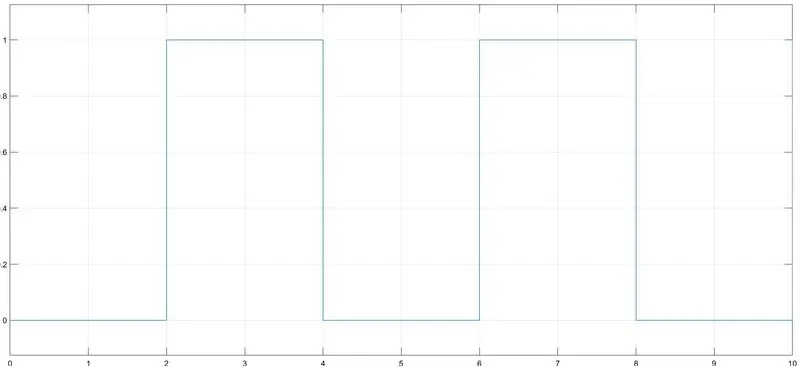
The pulse generator signal is represented in the graph above. We can see that the switch is closed and released every 2 seconds. On the other side, we have connected an ideal translational motion sensor to the solenoid, which is used to monitor the physical movement of the plunger.
The ideal translational motion sensor provides the output signal. We must convert the signals to simulink signals using the ps simulink converter, and then the output signal is fed into the scope.
We can inspect the output signals using the scope.
OUTPUT SIGNALS
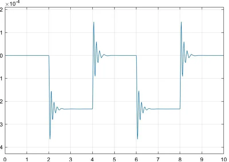
The output signals are described in the graph above. From this signal, we can see that from 0 to 2, the signal is stable, and then it begins to fluctuate for a second and then it becomes stable from 0 to 4 . As a result, we can say that the bell rings every 2 seconds.
CONCLUSION
In the pulse generator, give input as a time period of 2 seconds to open and close the switch. When the switch is closed, the solenoid block receives power from the battery and the plunger moves, striking the bell and producing sound.
The plunger movement can be monitored using an ideal translation motion sensor, and the signal is sent to the scope. And we get a signal in the output indicating that the bell rings every 2 seconds.
2)
Thermistor to sense the temperature of a heater & turn on or turn off the fan
We are going to sense the temperature by using a thermistor and turn the fan on and off for that. We are providing a temperature source here that is from 0 to 10 time duration the temperature is 20 °C and from 10 to 30 time duration the temperature is 27 °C. 30 to 50 degrees Celsius is 23 degrees Celsius. If the temperature rises above 25 degrees Celsius, the fan will turn on; otherwise, it will turn off.
MAIN SYSTEM
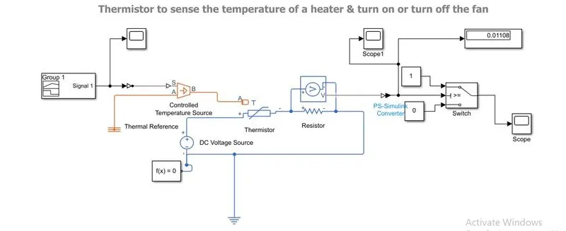
We can see in the above main system that there is a signal builder, controlled temperature source, thermistor, voltage sensor, switch, and scope.
The signal builder is used in this case to generate input signals based on the given condition.
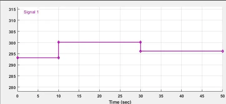
This is the input signal that we are providing in response to the given condition. We simply convert the Celsius value to Kelvins. So, in this case, there is a graph plotted between time and kelvins.
As stated in the condition time from 0 to 10, we want 20 °C so we convert it to kelvin, which is 293.15 k in graph, we can see that up to 10 the that is 20 °C and from 10 to 30 it is increased to 27°C, which is 300.15 k and from 30 to 50 again decreased in to 23 °C, which is 296.15 k under this condition, we given the input signals
The necessity is that the fan be turned on when the temperature is greater than 25 degrees Celsius. To achieve this aim, we use a voltmeter to determine the voltage of the circuit at various temperatures. As previously stated, if the temperature is greater than 25 °C, the fan is turned on; otherwise, it is turned off.
SIGNAL BUILDER

The signal builder is a block that will produce an output based on the conditions we provide.
CONTROLLED TEMPERATURE SOURCE
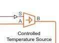
The regulated temperature source block is an ideal source of thermal energy, capable of maintaining a given temperature difference across the source regardless of the amount of heat flow absorbed by the device.
VOLTAGE SENSOR

The voltage sensor block is a representation of an ideal voltage sensor, which is a device that transforms voltage measured between two points in an electrical circuit into a physical signal proportional to the voltage.
SCOPE 1
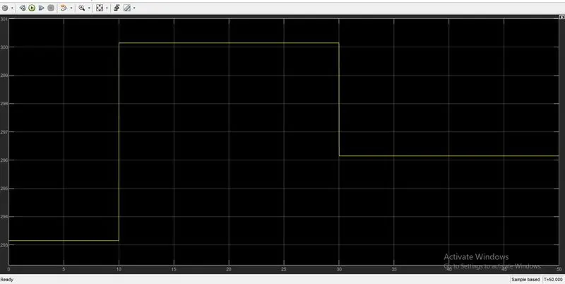
This is the output signal that we get after the voltage is sensed. We can see that the signal is passing under the specified conditions.
THRESHOLD VALUE
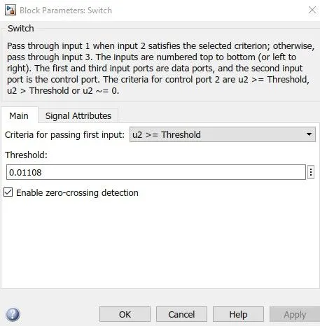
This is the value that we assign to the switch's threshold. We get a value in the display while we run the stimulation; the display is connected after the voltage sensor, so we get a value in the display that is the threshold value.
OUTPUT SIGNAL
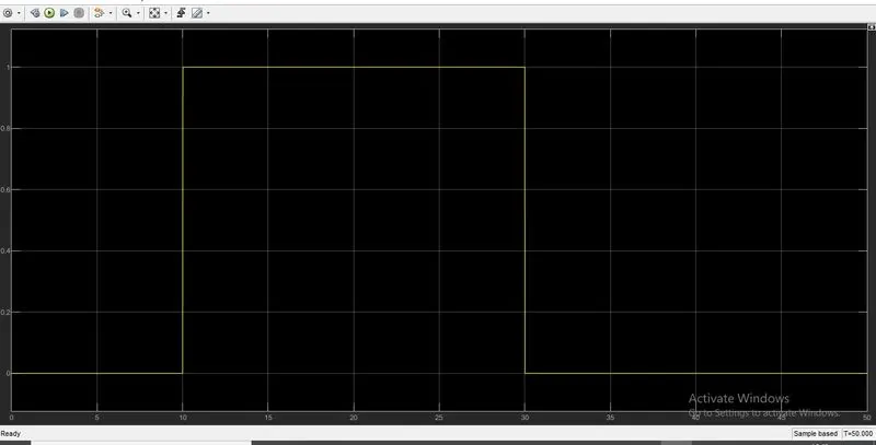
This is the output signal that we get after the stimulus. As you can see in the graph, when the temperature is greater than 25 °C, the fan is turned on. The temperature is higher than 25 °C in time 10 to 30, which is 27 °C.
So, we can see that the fan is off from 0 to 10, and on from 10 to 30, in this graph. The temperature is 27°C at that time, and in 30 to 50 the temperature drops to 23°C, so the fan is turned off.
CONCLUSION
Stimulate a fan for the input state, then turn it on and off depending on the temperature. The given condition is that when the temperature rises above 25 °C, the fan is turned on, and when the temperature rises below that, the fan is turned off.