Project-1: Powertrain for aircraft in runways
Part A:
1. Search and list out the total weight of various types of aircrafts.
Weight is the force generated by the gravitational attraction of the earth on the airplane. Each part of the aircraft has a unique weight and mass, and for some problems, it is important to know the distribution. But for total aircraft maneuvering, we only need to be concerned with the total weight and the location of the center of gravity. The center of gravity is the average location of the mass of any object.
An airplane is a combination of many parts- the wings, engines, fuselage, tail, payload, and fuel. Each part has a weight associated with it which the engineer can estimate, or calculate using Newton's weight equation
`W = m*g`
where,
w = the weight
m = mass
g = gravitational constant = 9.8 m/s
The mass of an individual component can be calculated if we know the size of the component and its chemical composition. Every material has a unique density.
Density (D) = `m/V`
Where,
V = volume
If we can calculate the volume we can fine mass
`m = D*V`
Then the total weight W of the aircraft is the sum of the weight of all of the individual components.
W = w(fuselage) + w(wing) + w(engines) + w(payload) + w(fuel) +........
Maximum Taxi Weight (MTW):
- The maximum taxi weight (MTW) is the maximum weight authorized for maneuvering an aircraft on the ground as limited by aircraft strength and airworthiness requirements. It includes the weight of the taxi and run-up fuel for engines and the auxiliary power unit (APU).
- It is greater than the MTOW due to the fuel that will be burned during the taxi and runup operations.
Maximum Takeoff Weight (MTOW):
- The maximum takeoff weight is the maximum weight authorized at brake release for takeoff, or at the start of the takeoff roll.
- The MTOW is always less than the MTW to allow for fuel burned during taxi by the engines and the APU.
Maximum Landing Weight (MLW):
The maximum weight authorized for the normal landing of an aircraft. It must not exceed the MTOW. The operation landing weight may be limited to a weight lower than the MLW by the most restrictive of the following requirements:
- Aircraft performance requirements for a given altitude and temperature.
- Noise requirements.
Maximum Zero Fuel Weight (MZFW):
The maximum permissible weight of the aircraft less all usable fuel and other specified usable agents. It is the maximum weight permitted before usable fuel and other specified usable fluids are loaded in specified sections on the airplane.

Types of Airplanes:
| SL No. | Aircraft Name | Empty Weight (kg) | Maximum Weight (kg) |
| 1 | Cessna 172 | 657.7 | 1,111.3 |
| 2 | Citation Jet M | 3,170.61 | 4,853.4 |
| 3 | Boeing 767 | 88,450.5 | 1,81,437 |
| 4 | Boeing 787 | 1,19,975 | 2,27,930 |
| 5 | Boeing 777 | 1,60,572 | 2,99,371 |
| 6 | Boeing 747 | 1,84,612 | 4,12,770 |
| 7 | Airbus A320 | 37,195 | 77,111 |
| 8 | Airbus A330 | 1,24,511 | 2,42,000 |
2. Is there any difference between ground speed and airspeed?
Ground Speed:
- Ground speed is the horizontal speed of an aircraft relative to the earth's surface. It is vital for accurate navigation to the destination that the pilot has an estimate of the ground speed that will be achieved during a flight.
- An aircraft diving vertically would have a ground speed of zero. The information displayed to passengers through the entertainment system of airline aircraft usually gives the aircraft ground speed rather than airspeed.
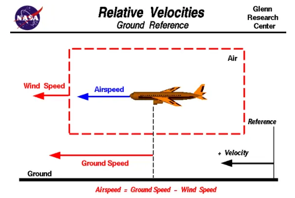
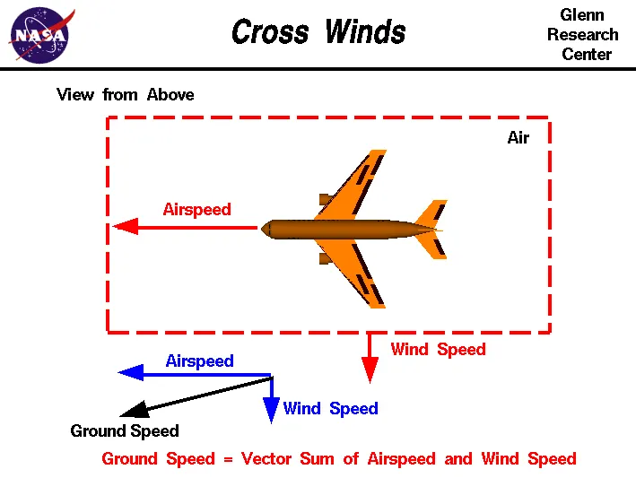
- Ground speed can be determined by the vector sum of the aircraft's true airspeed and the current wind speed and direction; a headwind subtracts from the ground speed, while a tailwind adds to it. Winds at other angles to the heading will have components of either headwind or tailwind as well as a crosswind component.
- An airspeed indicator indicates the aircraft's speed relative to the air mass. The air mass may be moving over the ground due to wind, and therefore some additional means to provide position over the ground is required. This might be through navigation using landmarks, radio-aided position location, an inertia navigation system, or GPS.
Airspeed:
Airspeed is the speed of an aircraft relative to the air. Among the common conventions for qualifying airspeed are indicated airspeed (IAS), calibrated airspeed (CAS) equivalent airspeed (EAS), true airspeed (TAS), and density airspeed (DAS).
- IAS is the reading of the airspeed of a gauge connected to a pitot-static system.
- CAS id indicated airspeed adjusted for pitot system position and installation error.
- EAS is calibrated airspeed adjusted for compressibility effects.
- TAS is equivalent airspeed adjusted for air density and is also the speed of the aircraft through the air in which it is flying.
- Calibrated airspeed is typically within a few knots of indicated airspeed, while equivalent airspeed decreases slightly from CAS as aircraft altitude increases or at high speeds.
- With EAS constant true airspeed increases as aircraft altitude increases. This is because air density decreases with a higher altitude, but an aircraft's wing requires the same amount of air particles flowing around it to produce the same amount of lift for a given angle of attack, thus the wing must move faster through thinner air than thicker air to obtain the same amount of lift.
3. Why is it not recommended to use aircraft engine power to move it on the ground at Airport?
- Boeing commercial airplanes are equipped with engines rated from 8200 to nearly 50000 kg of thrust. Such thrust levels provide for a safe takeoff, flight, and landing over a wide range of temperatures, altitudes, gross weights, and payload conditions. However, the exhaust wake from these engines can pose hazards in commercial airport environments. Operators and airport authorities must carefully consider these hazards and the resulting potential for injury to people and damage to or caused by baggage carts, service vehicles, airport infrastructure, and other airplanes.
- When modern jet engines are operated at rated thrust levels, the exhaust wake can exceed 603 km/h immediately after the engine exhaust nozzle. This exhaust flow field extends aft in a rapidly expanding cone, with portions of the flow field contacting and extending aft along the pavement surface. Exhaust velocity components are attenuated with increasing distance from the engine exhaust nozzle. However an airflow of 483 km/h can still be present at the empennage, and significant people and equipment hazards will persist hundreds of feet beyond this area. At full power, the exhaust wake speed can typically be 240 km/h at 61m beyond the airplane and 80 to 161 kn/h well beyond this point.
- One approach to relating these values to airport operations is to consider the hurricane intensity scale used by the US National Oceanic and Atmospheric Administration. A Category 1 hurricane has sustained winds of 119 to 153 km/h. At these velocities, minimal damage to stationary building structures would be anticipated, but more damage to unanchored mobile homes and utility structures would be expected. An idling airplane can produce a compact version of a Category 3 hurricane, introducing an engine wake approaching 192 km/h with temperatures of `38^0`C. This wake velocity can increase two or three times as the throttles are advanced and the airplane begins to taxi.
- At the extreme end of the intensity, the scale is a Category 5 hurricane, with winds greater than 249 km/h. Residential and industrial structures would experience roof failure, with lower-strength structures experiencing complete collapse. Mobile homes, utility buildings, and utilities would be extensively damaged or destroyed, as would trees, shrubs, and landscaping.
4. How an aircraft is pushed to runway when its ready to take off?
- Taxiing is the movement of an aircraft on the ground, under its own power, in contrast to towing or pushback where the aircraft is moved by a tug. the aircraft usually moves on wheels, but the term also includes aircraft with skis or floats.
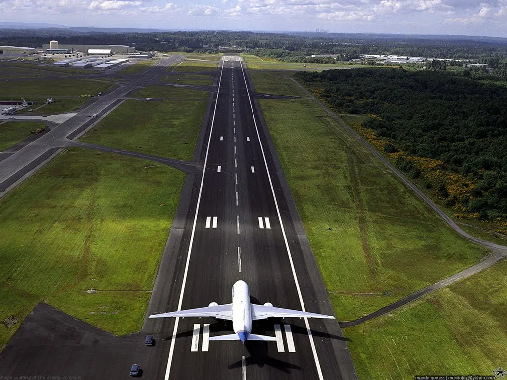
- An airplane uses taxiways to taxi from one place on an airport to another, for example, when moving from a hangar to a runway. The term taxiing is not used for the accelerating run along a runway prior to takeoff, or the decelerating run immediately after landing, which is called takeoff roll and landing rollout, respectively.
- When taxiing, aircraft travel slowly. This ensures that they can be stopped quickly and do not risk wheel damage or larger aircraft if they accidentally turn off the paved surface. Taxi speeds are typically 30 to 35 km/h.
Equipments:
Moving Light Aircraft:
Very small airplanes may be moved by human power alone. The airplane may be pushed or pulled by landing gear or wing struts since they are known to be strong enough to drag the airplane through the air. To allow for turns, a person may either pick up or push down on the tail to raise either the nose wheel or tail wheel off the ground, then rotate the airplane by hand. A less cumbersome method involves attaching a short tow bar to either the nose wheel or tail wheel, which provides a solid handhold and leverage to steer with, as well as eliminates the danger of handling the propeller. These tow bars are usually a lightweight aluminum alloy construction which allows them to be carried on board the airplane. Other small tow bars have a powered wheel to help move the airplane, with power sources as diverse as lawnmower engines or battery-operated electric drills. However, powered tow bars are usually large and heavy to pe practically carried on small airplanes.
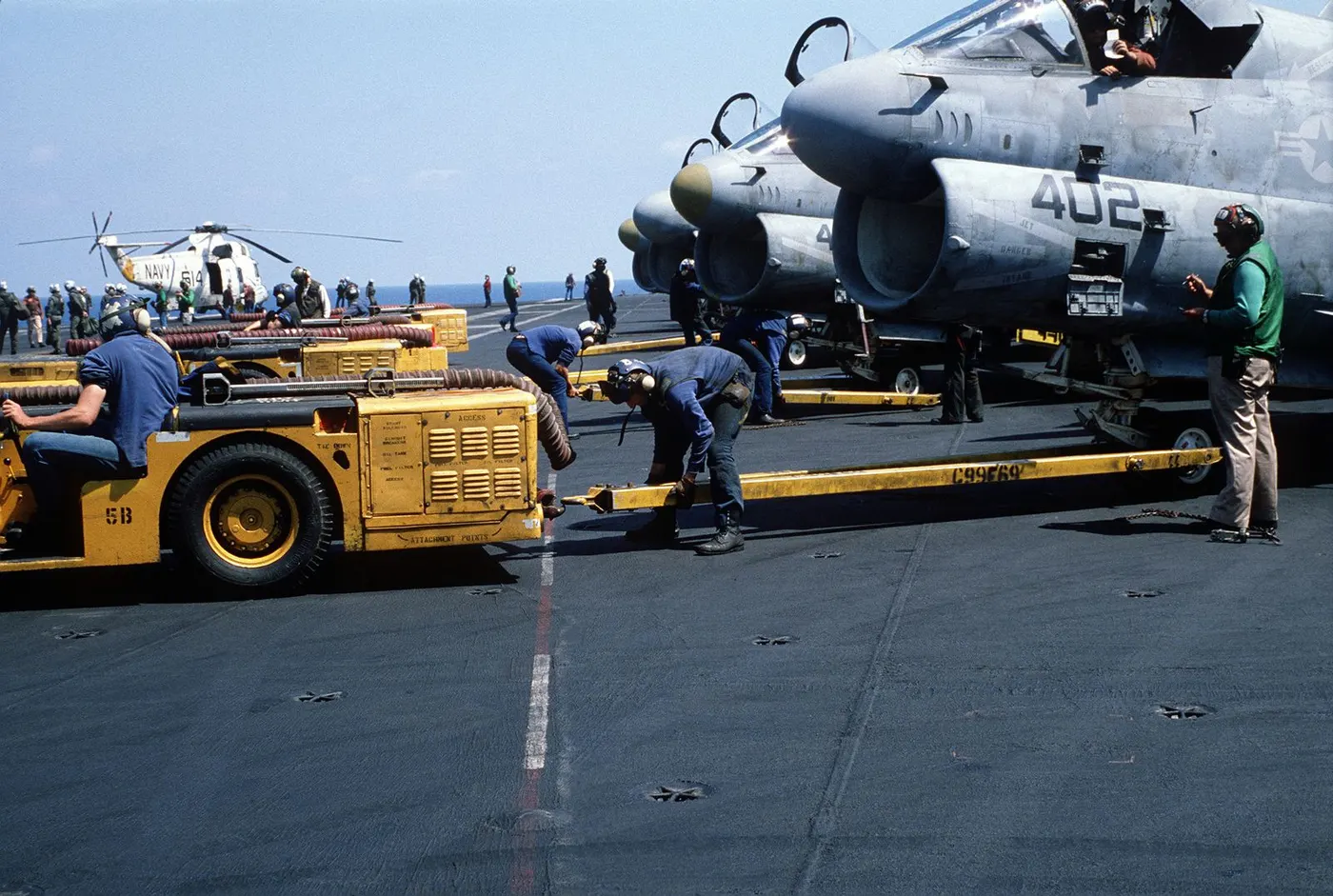
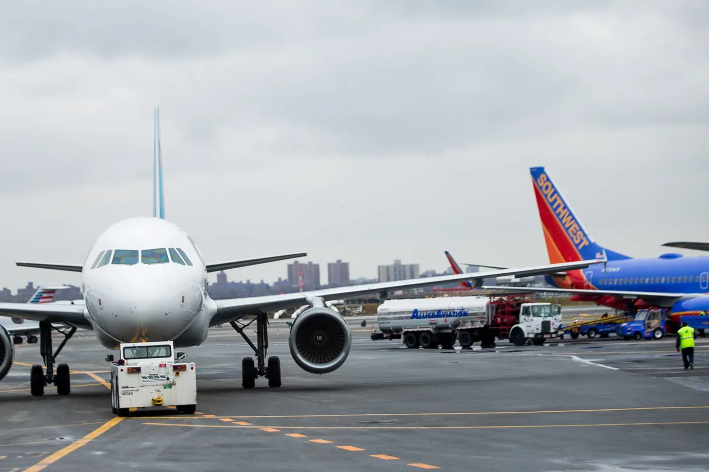
Tractors and Towbars:
Large aircraft cannot be moved by hand and must have a tractor or tug. Pushback tractors use a low-profile design to fit under the aircraft's nose. For sufficient traction, the tractor must be heavy and most models can have extra ballast added. A typical tractor for large aircraft weighs up to 54 tonnes and has a drawbar pull of 334 kN. Often the driver's cabin can be raised for increased visibility when reversing and lowered to fit under aircraft.
5. Learn about take off power, tire design, rolling resistance, tire pressure, brake forces when landing.
Takeoff Power:
Takeoff is the phase of flight in which an aerospace vehicle leaves the ground and becomes airborne. For light aircraft, usually, full power is used during takeoff. Large transport category aircraft may use a reduced power for takeoff, where less than full power is applied in order to prolong engine life, reduce maintenance costs and reduce noise emissions. In some emergency cases, the power used can then be increased to increase the aircraft's performance. The nose is raised to a nominal 5° to 15° nose-up pitch attitude to increase lift from the wings and effect liftoff. For most aircraft, attempting a takeoff without a pitch-up would require cruise speeds while still on the runway. The speeds needed for takeoff are relative to the motion of the air. A headwind will reduce the ground speed needed for takeoff air speeds for jetliners are in the range of 240-285 km/h. Light aircraft, such as a Cessna 150, takeoff at around 100 km/h. Ultralights have even lower takeoff speeds. For a given aircraft, the takeoff speed is usually dependent on the aircraft's weight; the heavier the weight, the greater the speed needed.
Tire Design:
- An aircraft tire is designed to withstand extremely heavy loads for short durations. The number of tires required for aircraft increases with the weight of the aircraft, as the weight of the airplane needs to e distributed more evenly. Aircraft tire tread patterns are designed to facilitate stability in high crosswind conditions, to channel water away to prevent hydroplaning, and for the braking effect.
- Aircraft tires also include fusible plugs designed to melt at a certain temperature. Tires often overheat if maximum braking is applied during an aborted takeoff or an emergency landing. The fuses provide a safer failure mode that prevents tire explosions by deflating in a controlled manner, thus minimizing damage to aircraft and objects in the surrounding environments.
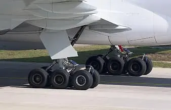
- When it comes to safety, tires are on of the most important components of aircraft. They help to absorb the shock of landing and provide cushioning. It also provides the necessary traction for the braking and stopping of an aircraft. A Boeing 737NG & 737MAX uses 6 wheels, Boeing 787 uses 10 wheels, Boeing 777 uses 14 wheels and Airbus A380 uses 22 wheels. Aircraft tires work under extreme conditions, carrying up to 340 tons and accelerating at over 250 km/h at takeoff, in addition to enduring varied environmental stress when in flight and taxiing.
An aircraft tire is constructed for the purpose it serves
- They support the weight of an aircraft while it is on the ground.
- It also provides the necessary traction for braking and stopping an airplane.
- The tire also helps to absorb the shock of landing and provides cushioning for the roughness of takeoff, roll-out, and taxi operation.
Unlike car or truck tire airplane tire needs to design for different purpose so different parts are needed to design very carefully like
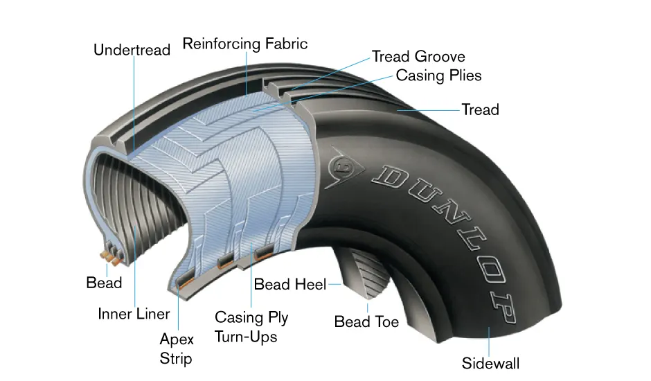
- Tread: The tread is made of rubber mixed with other additives to obtain the desired level of toughness, durability, and resistance to wear. The tread pattern is designed to aircraft operational requirements, with the ribbed tread design used widely due to its good traction under varying runway conditions.
- Sidewall: The sidewall is a protective layer of rubber that covers the outer casing ply. It extends from the tread edge to the bead area.
- Tread Reinforcing Ply: One or more layers of fabric that strengthens and stabilizes the tread area of high-speed operation. It also serves as a reference for the buffing process when tires are retreaded.
- Buff Line Cushion: The buff line cushion is made of rubber compound to enhance the adhesion between the tread reinforcing ply and the breakers or casing plies. It is of sufficient thickness to allow for the removal of the old tread when the tire is retreaded.
- Breakers: Breakers are reinforcing plies of rubber-coated fabric placed under the buff line cushion to protect casing plies and strengthen and stabilize the tread area. They are considered an integral part of the casing construction.
- Casing Plies: Alternate layers of rubber-coated fabric provide the strength of the tire.
- Wire Bead: Hoops of high tensile strength steel wire that anchor the casing plies and provide a firm mounting surface on the wheel. The outer edge of the bead that fits against the wheel flange is called the bead heel. The inner bead edge is called the bead toe.
- Apex Strip: A wedge of rubber affixed to the top of the bead bundle.
- Flippers: Layers of rubberized fabric that help anchor the bead wires to the casing and improve the durability of the tire.
- Ply Turnups: The casing plies are anchored by wrapping them around the wire beads, thus forming the ply turnups.
- Chafer: A protective layer of rubber and fabric located between the casing plies and wheel to minimize chafing.
- Liner: In tubeless tires, the liner is a layer of low permeability rubber that acts as a built-in tube and restricts gas from diffusing into the casing plies. In tube-type tires, a thinner liner is used to prevent tube chafing against the inside ply.
Tire Pressure:
- To perform as designed, an aircraft tire must be properly inflated. The aircraft manufacturer's maintenance data must be used to ascertain the correct inflation pressure for a tire on a particular aircraft. Do not inflate to pressure for a tire on a particular aircraft. Do not inflate to a pressure displayed on the sidewall of the tire or by how the tire looks. Tire pressure is checked while under load and is measured with the weight of the aircraft on the wheels. Loaded versus unloaded pressure readings can vary as much as 4 percent. Tire pressure measured with the aircraft on jacks or when the tire is not installed is lower due to the larger volume of the inflation gas space inside of the tire. On a tire designed to be inflated to 160 psi, this can result in a 6.4 psi error. A calibrated pressure gauge should always be used to measure inflation pressure. Digital and dial-type pressure gauges are more consistently accurate and preferred.
- Aircraft tires disperse the energy from landing, rollout, taxi, and takeoff in the form of heat. As the tire flexes, heat builds and is transferred to the atmosphere, as well as to the wheel rim through the tire bead. The heat from braking also heats the tire externally. A limited amount of heat is able to be handled by any tire beyond which structural damage occurs.
- An improperly inflated aircraft tire can sustain internal damage that is not readily visible and that can lead to tire failure. Tire failure upon landing is always dangerous. An aircraft tire is designed to flex and absorb the shock of landing. The temperature rises as a result. However, an underinflated tire may flex beyond the design limits of the tire. This causes excessive heat build-up that awakens the carcass construction. To ensure tire temperature is maintained within the proper range on a daily basis or before each flight if the aircraft is only flown periodically.
Rolling Resistance:
Rolling resistance sometimes called rolling friction or rolling drag is the force resisting the motion when a body rolls on a surface.
The rolling resistance coefficient is defined by the following equation:
`F = mu*N`
Where,
F = rolling resistance force
`mu`= rolling resistance coefficient (dimensionless)
N = normal force
Brake Force while Landing:
Aircraft brakes stop a moving aircraft by converting its kinetic energy to heat energy by means of friction between rotating and stationary discs located in brake assemblies in the wheels. Brakes provide this critical stopping function during landings to enable airplanes to stop within the lengths of the runway. They also stop aircraft during rejected takeoff events, in which an attempted takeoff from the ground due to engine failure, tire blowout, other system failures, or direction from air traffic control. Aircraft brakes also prevent the motion of the aircraft when it is parked, limit its speed during taxiing, and can even help steer the aircraft on the ground by applying different levels of braking force to the left and right side brakes. Aircraft brakes work in conjunction with other brake mechanisms such as thrust reversers, air brakes, and spoilers. Thrust reversers are surfaces that are deployed into the path of the aircraft. Air brakes and spoilers are flight control surfaces that create additional aerodynamic drag when deployed into the path of air flowing around the aircraft.
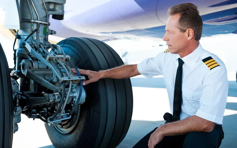
The following brake methods are used to decelerate the aircraft until it stops:
- Engine brake/Thrust reverser
- Wheel brake
- Mechanical brake
Engine Brake: The most important action to achieve deceleration from a speed at which the engines are still producing forward motion is to select all thrust/power levers to the ground idle position promptly, and if available, continue the action through to the selection of reverse thrust or reverse propeller pitch. This is the first action to begin deceleration and must especially be achieved without delay when a high-speed rejected takeoff is initiated. Thrust reversers are reverse propeller pitch is most effective at high speeds. Once the aircraft groundspeed has reduced sufficiently, thrust levers should be returned to the ground idle position to prevent ingestion of any foreign object debris which could be present, with reversers stowed once at taxi speed.
Wheel Brake: To be effective braking action at any speed depends upon sufficient friction existing between the tires and the runway surface achieved through freely rotating wheels. Anti-skid units are fitted to the braking systems of all modern transport aircraft. They modulate applied brake system hydraulic pressure before it is transmitted to the actuators in the brake units so as to obtain optimum braking based upon wheel traditional speed data received at the unit. A minimum wheel rotational speed must be detected before any brake application will be achieved to prevent tire destruction resulting from a locked wheel and to guard against the risk of aquaplaning on wet or ice runway surfaces.
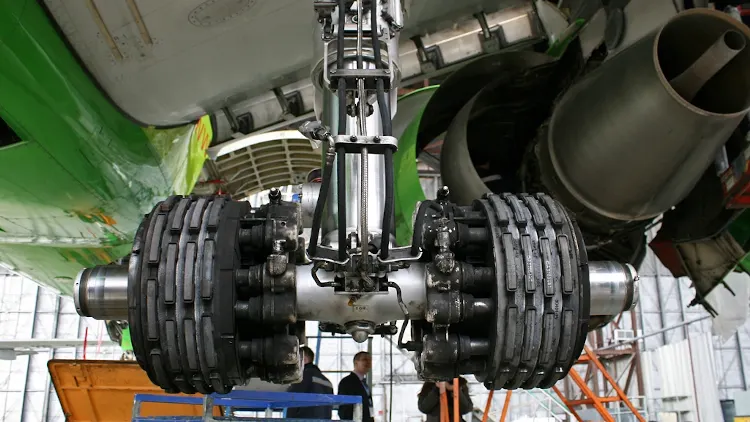
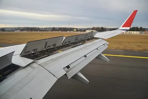
Mechanical Brakes: The mechanical deflection of parts of the wing upper surfaces and tail cone assembly can assist deceleration in two ways:
- Directly, by increasing aerodynamic drag on the moving aircraft. This can be achieved by raising upper wing surface pales called ground spoilers or by operating a tail cone clamshell-type air brake. Both systems can also be used in the air on some aircraft types as inflight air brakes, but the extent of their operation may be less in the airborne case than in the ground case. Extreme care may be needed if it is permissible for a particular aircraft type to carry out a rejected landing after initial touchdown since not all ground settings of deployed spoilers and air brakes necessarily auto retract to the settings needed for a safe initial climb away.
- Indirectly by increasing the effective downward load on the landing gear and thereby increasing the efficiency of wheel braking.
Part B:
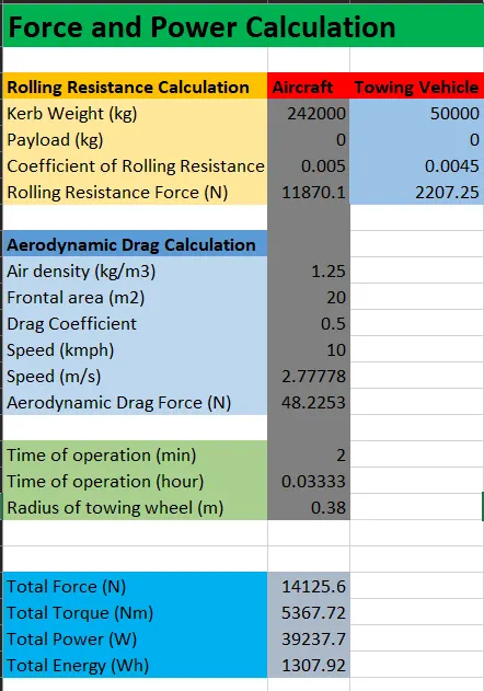
6. A. With necessary assumptions, calculate the force and power required to push / pull an aircraft by a towing vehicle.
| S.L No. | Parameters | Value |
| 1 | Mass of Aircraft (Airbus A330) in kg | 242000 |
| 2 | Acceleration due to gravity in m/s2 | 9.81 |
| 3 | Pressure in aircraft tire in bar | 14 |
| 4 | The velocity of aircraft in km/h | 10 |
| 5 | Mass of towing vehicle in kg | 50000 |
| 6 | Pressure in the tow vehicle tire in psi | 32 |
| 7 | Velocity of the tow vehicle in km/h | 10 |
| 8 | Density of the air in kg/m3 | 1.25 |
| 9 | Frontal area in m2 | 20 |
| 10 | Coefficient of rolling resistance for aircraft | 0.005 |
| 11 | Coefficient of rolling resistance for tow vehicle | 0.0045 |
| 12 | Coefficient of drag | 0.5 |
| 13 | Radius of tow wheel in mm | 0.38 |
| 14 | Towing time in min | 2 |
Rolling Force:
For aircraft
Rolling force is given as `Fundersetr() = mu*m*g`
Where,
`Fundersetr() =`rolling force in N
`mu=`coefficient of rolling resistance
m = mass of aircraft in kg
g = acceleration due to gravity in `m/s^2`
`mu`can be calculated by `mu=0.005+1/p*((0.01+0.0095)(v/100)^2)`
where,
p = tire pressure in bar
v = velocity in km/h
By substituting the value in F we get
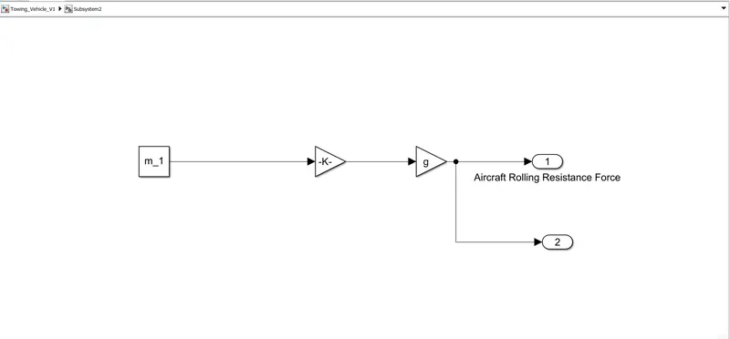
`Fundersetr()=0.005*242000*9.81=11870N` ............................................eq(1)`
For towing vehicle rolling friction force is
`Fundersetr()=mu*m*g`
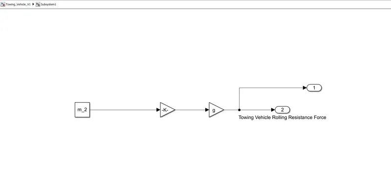
`Fundersetr()=0.0045*50000*9.81=2207.25`N...........................................eq(2)
Drag force calculation:
`CundersetD()=(FundersetD())/(A(rho*V^2)/(2))`
Where,
`FundersetD()`= Drag Force
`CundersetD()`= Drag coefficient
A = Reference area
`rho=`density of the fluid
V = flow velocity relative to the objective
By substituting in drag force equation we get,
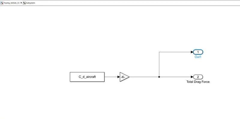
`FundersetD()=0.5*1.25*0.5*20*(10*5/18)^2=48.225`N...............................eq(3)
Now, the total force is
`Fundersett()=11870.1+2207.25+48.225`
`Fundersett()=14125.575`N
Power:
`P=FundersetT()*v`
`P=14125.575*10*5/18`
`P=39.23`kW
Torque:
`T=Fundersett()*r`
`T=14125.57*0.38`
`P=5367.71`Nm
Energy:
`E=P.t`
`E=39.23*120/3600`
E = 1.307 kWh
B. Develop the model for the calculated force and power using Simulink.
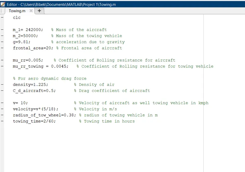
clc

m_1= 242000;   % Mass of the aircraft
m_2=50000;     % Mass of the towing vehicle
g=9.81;        % acceleration due to gravity
frontal_area=20; % Frontal area of aircraft

mu_rr=0.005;    % Coefficient of Rolling resistance for aircraft
mu_rr_towing = 0.0045;   % Coefficient of Rolling resistance for towing vehicle

% For aerodynamic drag force
density=1.225;          % Density of air
C_d_aircraft=0.5;       % Drag coefficient of aircraft

v= 10;                  % Velocity of aircraft as well towing vehicle in kmph
velocity=v*(5/18);      % Velocity in m/s
radius_of_tow_wheel=0.38; % radius of towing vehicle in m
towing_time=2/60;         % Towing time in hours
Aircraft Rolling Resistance Force Subsystem
Towing Vehicle Rolling Resistance Force Subsystem
Total Drag Force Subsystem
Complete Simulink Model:
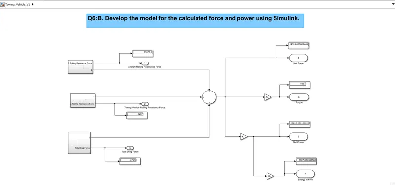
The display output values match the calculated values.
7. A. Design an electric powertrain with type of motor, it’s power rating, and energy requirement to fulfill aircraft towing application in Simulink. Estimate the duty cycle range to control the aircraft speed from zero to highest. Make all required assumptions. Prepare a table of assumed parameters. Draw a block diagram of powertrain.
(Hint :DC7 Block)
From the above, it is clear that the power required for towing is 39.23kW. For this the 3-phase induction motor with a rating is given below:
| SL No. | Parameters | Value |
| 1 | Motor Rating in kW | 45 |
| 2 | Number of phases | 3 |
| 3 | Horsepower | 60 |
| 4 | Frequency in Hz | 50 |
| 5 | Rated voltage in V, rated current in A | (240,187.5), (380,118.42), (415,108.43) |
| 6 | Efficiency | >80% |
Power input:
`Punderseti()=V*I`
`Punderseti()=415*108.43`
`Punderseti()=45kW`
Energy:
`E=P*t`
`E=45*120/3600`
E = 1.5 kWh
Duty cycle:
`D=(Punderseto())/(Punderseti())`
`D = 39.23/45`
D = 0.871
The duty cycle for towing vehicle to reach from zero to highest is 87.1%
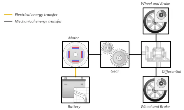
The block model is:
B. Also, Design the parameters in excel sheet.