Week-7 Challenge: DC Motor Control
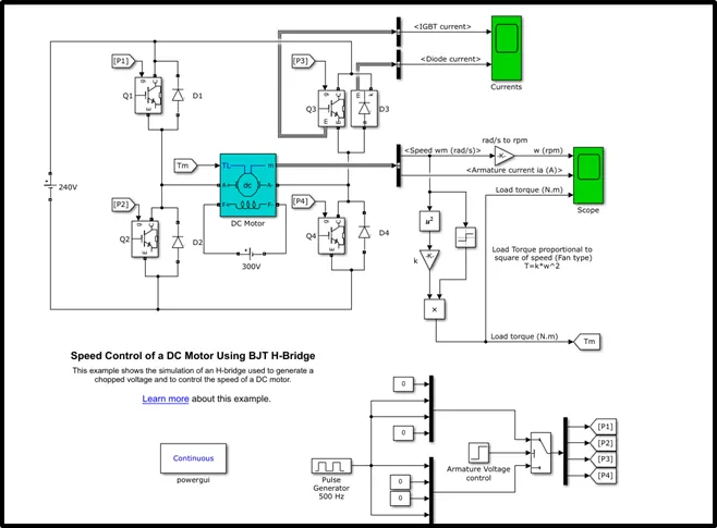
1. A. Explain a MATLAB demo model named ‘Speed control of a DC motor using BJT H-bridge’.
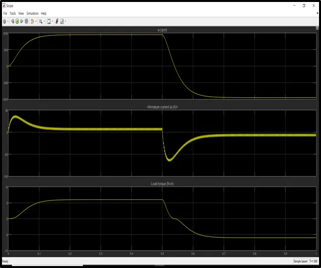
B. Comment on the armature current shoot-up from the scope results.
C. Refer to the help section of ‘The Four-Quadrant Chopper DC Drive (DC7) block’. Compare it with the H-bridge model.
This example shows the simulation of an H-bridge used to generate a chopped voltage and to control the speed of a DC motor.
Description:
The Bipolar Junction Transistor (BJT) when used for power switching applications, operates as an IGBT. When it is conducting (BJT operating in the saturated region), a forward voltage Vf is developed between collector and emitter (in the range of 1 V). Therefore, the IGBT block can be used to model the BJT device.
The IGBT block does not simulate the gate current controlling the BJT or IGBT. The switch is controlled by a Simulink® signal (1/0). The DC motor uses the preset model (5 HP 24V 1750 rpm).
It simulates a fan type load (where Load torque is proportional to square of speed). The armature mean voltage can be varied from 0 to 240 V when the duty cycle (specified in the Pulse Generator block) is varied from 0 to 100%.
The H-bridge consists of four BJT/Diode pairs (BJT simulated by IGBT models).
Two transistors are switched simultaneously: Q1 and Q4 or Q2 and Q3. When Q1 and Q4 are fired, a positive voltage is applied to the motor and diodes D2-D3 operate as free-wheeling diodes when Q1 and Q4 are switched off. When Q2 and Q3 are fired, a negative voltage is applied to the motor and diodes D1-D4 operate as free-wheeling diodes when Q2 and Q3 are switched off.
Simulation
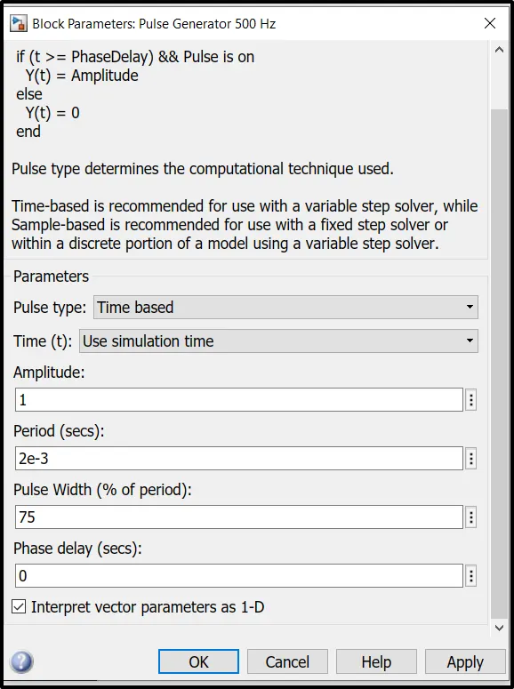
The motor starts in the positive direction with a duty cycle of 75% (mean DC voltage of 180V). At t= 0.5 sec., the armature voltage is suddenly reversed and the motor runs in the negative direction.
'Scope' shows motor speed, armature current and load torque and 'Currents' shows currents flowing in BJT Q3 and diode D3
Actual model:
Pulse generator:
With duty cycle of 75%
Simulation output for actual model:motor speed, armature current and load torque .
Pulse generator:
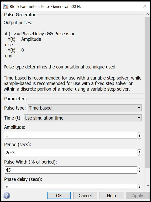
With duty cycle of 45%
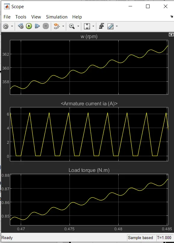
Simulation output for modified model:motor speed, armature current and load torque .
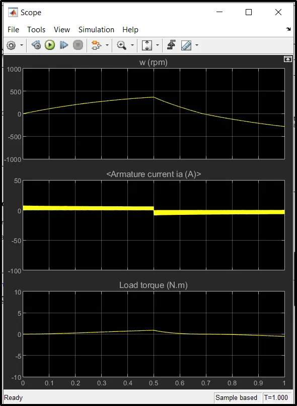
The armature current shoot-up is reduced when the duty cycle is reduced from the default 75% to 45%.
Result:
The armature current shoot up when motor changes direction from forward to reverse, this has to be overcomed. For this duty cycle which is 75% (Pulse Width) now is reduced and observe the changes in the results. Here the speed of the motor is reduced to 400rpm(approx) in forward motoring with 6.5A current(approx)
Refer to the help section of ‘The Four-Quadrant Chopper DC Drive (DC7) block’. Compare it with the H-bridge model.
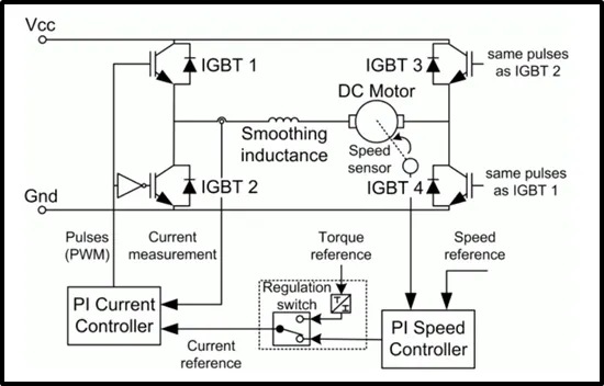
The Four-Quadrant Chopper DC Drive (DC7) block represents a four-quadrant, DC-supplied, chopper (or DC-DC PWM converter) drive for DC motors. This drive features closed-loop speed control with four-quadrant operation. The speed control loop outputs the reference armature current of the machine. Using a PI current controller, the chopper duty cycle corresponding to the commanded armature current is derived. This duty cycle is then compared with a sawtooth carrier signal to obtain the required PWM signals for the chopper.
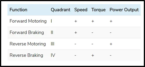
The main advantage of this drive, compared with other DC drives, is that it can operate in all four quadrants (forward motoring, reverse regeneration, reverse motoring, and forward regeneration). In addition, due to the use of high switching frequency DC-DC converters, a lower armature current ripple (compared with thyristor-based DC drives) is obtained. However, four switching devices are required, which increases the complexity of the drive system.
Comparison of applications
H-Bridges like the 4 quadrant choppers are also capable of the braking operation without using air resistance or friction or physical brakes to bring the motor to rest.
4 quadrant DC choppers are more commonly used in automobiles whereas BJT H-bridges are commonly used in robotics and electro-mechanical devices.
Unlike 4 quadrant DC choppers, BJT H-bridges are not capable of performing regenerative braking but they can perform dynamic braking.It is this difference that makes 4 quadrant DC choppers useful in hybrid and electric vehicles.
Controlling motor operation:
• In 4 quadrant DC choppers, the current signals are interrupted with one another to change the direction of rotation of the motor. This is done by a speed reference or a drive cycle from which the speed values are converted to current signals which interrupt one another to change the rotation of direction of the motor.
- In BJT H-bridges, the polarity of the current is reversed (depending on the duty cycle) to change the direction of rotation of the motor.
Comparison of Simulation timings:
- The current signals in 4 quadrant DC choppers are chopped meaning that they are not continuous, they are discrete and so take less time for simulations.
- BJT H-bridges, the current values are not chopped, meaning that they are continuous and so take more time for simulations.
Finally, in 4 quadrant DC choppers, a Pl controller is used to control the speed and the current and in the H-bridge, this is not implemented.
2. Develop a 2-quadrant chopper using simulink
& explain the working of the same with the relevant results. (Refer to article - Multiquadrant operation of motor )
Chopper:
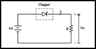
A chopper is a static device that converts fixed DC input voltage to a variable DC output voltage.
On this basis, there are two types of chopper: Step-up and Step-down Chopper.
A chopper whose average value of DC output voltage is more than the fixed DC input voltage is called Step-up Chopper and
a chopper whose average value of DC output voltage is less than the fixed DC input voltage is called Step-down Chopper.
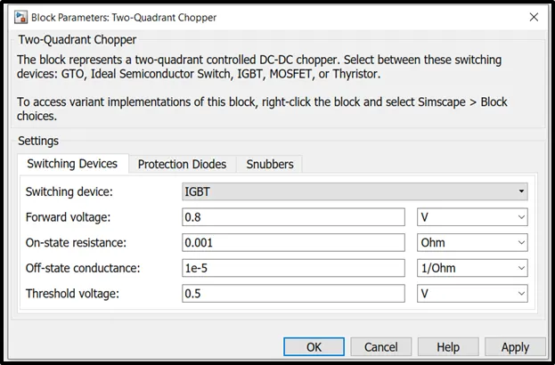
The Two-Quadrant Chopper block represents a two-quadrant controlled chopper for converting a fixed DC input to a variable DC output. The block contains two switching devices. Options for the type of switching devices are:
GTO — Gate turn-off thyristor. For information about the I-V characteristic of the device, see GTO.
Ideal semiconductor switch — For information about the I-V characteristic of the device, see Ideal Semiconductor Switch.
IGBT — Insulated-gate bipolar transistor. For information about the I-V characteristic of the device, see IGBT (Ideal, Switching).
MOSFET — N-channel metal-oxide-semiconductor field-effect transistor. For information about the I-V characteristic of the device, see MOSFET (Ideal, Switching).
Thyristor — For information about the I-V characteristic of the device, see Thyristor (Piecewise Linear).
Averaged Switch.
Two types of variants of Two-Quadrant Chopper:
Variant 1:
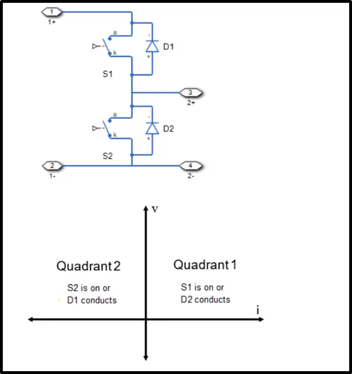
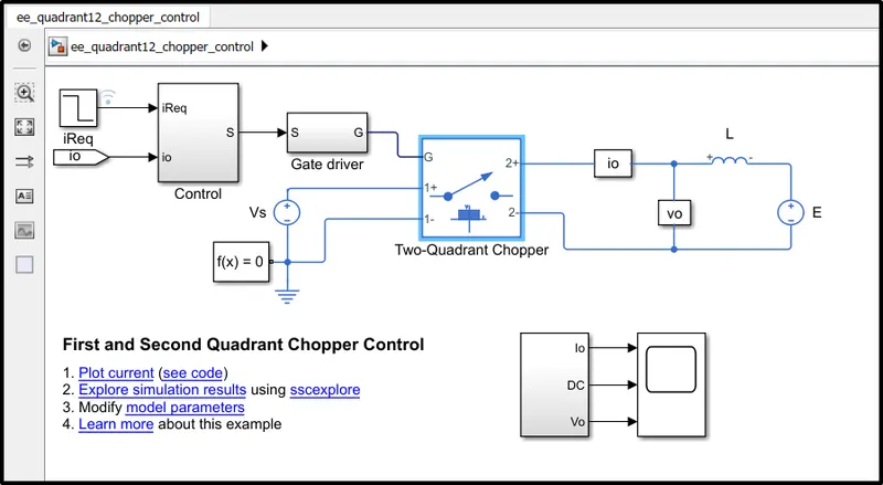
Simulink model:
This example shows how to control a two-quadrant chopper. The two-quadrant chopper operates in the first and second quadrants, allowing positive and negative output current.
The Control subsystem implements a simple PI-based control algorithm for controlling the output current.
The load of the system is considered constant throughout the simulation.
Switching device:
Simulation results:
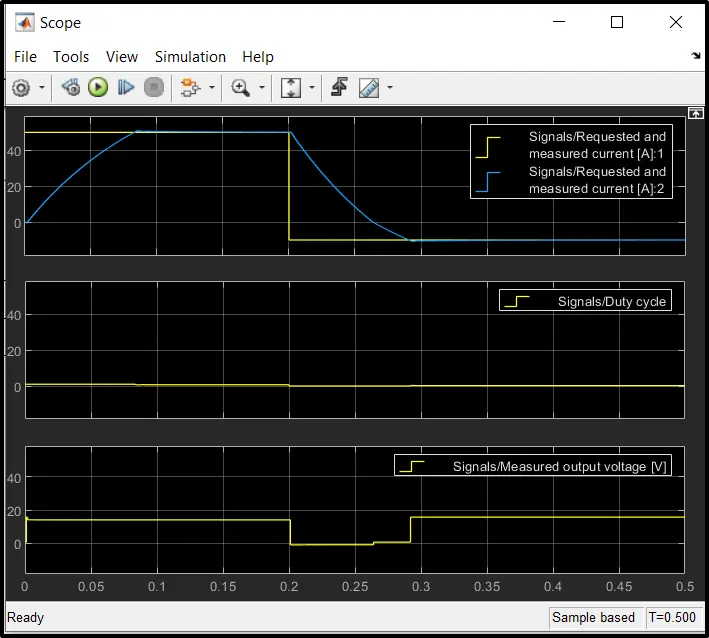
Variant 2: Quadrant 1-4 chopper control:
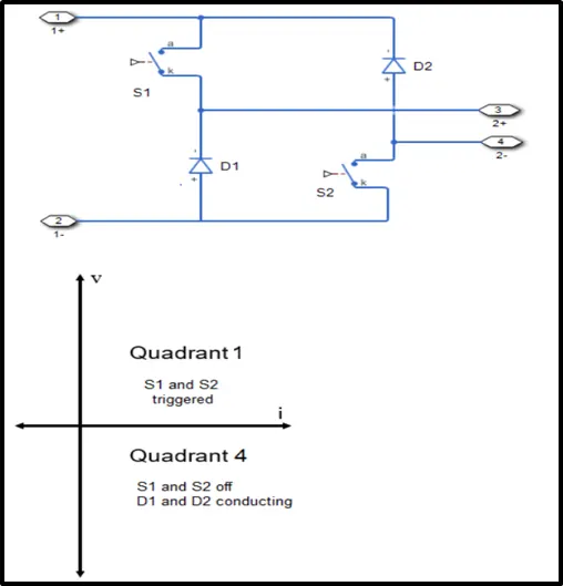
Variant 2: Quadrant 1-4 chopper control- Simulink model:
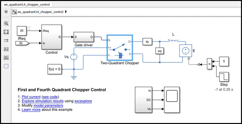
This example shows how to control a two-quadrant chopper. The two-quadrant chopper operates in the first and fourth quadrants, allowing positive and negative output voltage.
The Control subsystem implements a simple PI-based control algorithm for controlling the output current.
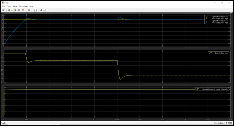
The total simulation time (t) is 0.5 seconds. At t = 0.25 seconds, the polarity of the load DC source E is changed.
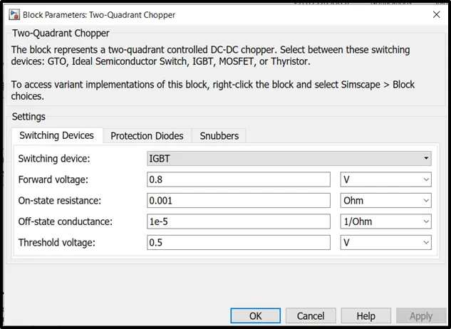
Switching devices:
IGBT is used as switching device.
Simulation results:
3. Explain in a brief about operation of BLDC motor.
Brushless DC motors (BLDC)
- A motor converts supplied electrical energy into mechanical energy.
- Various types of motors are in common use.
- Among these, brushless DC motors (BLDC) feature high efficiency and excellent controllability, and are widely used in many applications.
- The BLDC motor has power-saving advantages relative to other motor types.
Types of Motor:
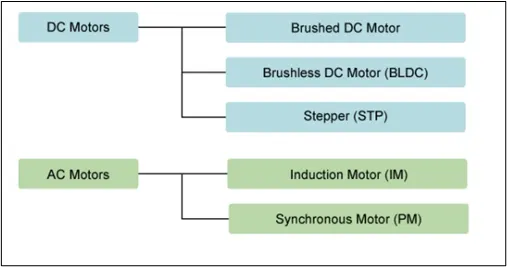
Machines ranging from simple devices like drills to complex equipment like industrial robots all make use of brushless DC motors that convert electrical energy into rotational motion.
Working principle of BLDC motor:
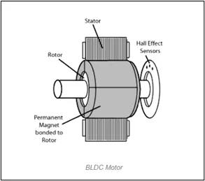
Both types of motors operate based on a similar principle, in which the rotational motion is generated through the attraction and repulsion of magnetic poles of permanent and electromagnets.
However, the way these motors are controlled is very different. BLDCs require a complex controller to convert a single DC power to three-phase voltage, whereas a brushed motor can be controlled by regulating the DC voltage.
As their name implies, brushless DC motors do not use brushes. With brushed motors, the brushes deliver current through the commutator into the coils on the rotor. Instead, the BLDC motor's rotor is a permanent magnet; the coils do not rotate, but are instead fixed in place on the stator. Because the coils do not move, there is no need for brushes and a commutator.
With the brushed motor, rotation is achieved by controlling the magnetic fields generated by the coils on the rotor, while the magnetic field generated by the stationary magnets remains fixed. To change the rotation speed, you change the voltage for the coils. With a BLDC motor, it is the permanent magnet that rotates; rotation is achieved by changing the direction of the magnetic fields generated by the surrounding stationary coils. To control the rotation, you adjust the magnitude and direction of the current into these coils.
- The principles for the working of BLDC motors are the same as for a brushed DC motor, i.e., the internal shaft position feedback.
- In the case of a brushed DC motor, feedback is implemented using a mechanical commutator and brushes.
- Within BLDC motor, it is achieved using multiple feedback sensors.
- In BLDC motors we mostly use a Hall-effect sensor, whenever rotor magnetic poles pass near the hall sensor, they generate a HIGH or LOW-level signal, which can be used to determine the position of the shaft.
- If the direction of the magnetic field is reversed, the voltage developed will reverse too.
Advantages of BLDC motor:
- Better speed versus torque characteristics
- High dynamic response
- High efficiency
- Long operating life due to a lack of electrical and friction losses
- Noiseless operation
- Higher speed ranges
Applications of BLDC motor:
The cost of the Brushless DC Motor has declined since its presentation, because of progressions in materials and design. This decrease in cost, coupled with the numerous focal points it has over the Brush DC Motor, makes the Brushless DC Motor a popular component in numerous distinctive applications. Applications that use the BLDC Motor include, yet are not constrained to:
- Consumer electronics
- Transport
- Heating and ventilation
- Industrial engineering
- Model engineering
Controlling a BLDC motor:
-
The Control unit is implemented by microelectronic has several high-tech choices. This may be implemented using a micro-controller, a dedicated micro-controller, a hard-wired microelectronic unit, a PLC, or similar another unit.
The Analog controller is still using, but the can not process feedback messages and control accordingly. With this type of control circuits, it is possible to implement high-performance control algorithms, such as vector control, field-oriented control, high-speed control all of which are related to electromagnetic state of the motor.
-
Furthermore outer loop control for various dynamics requirements such as sliding motor controls, adaptive control, predictive control…etc are also implemented conventionally.
Besides all these, we find high-performance PIC (Power Integrated Circuit), ASIC (Application Specific Integrated Circuits) …etc. that can greatly simplify the construction of the control and the power electronic unit both. For example, today we have complete PWM (Pulse Width Modulation) regulator in a single IC that can replace the entire control unit in some systems. Compound driver IC can provide the complete solution of driving all six power switches in a three-phase converter. There are numerous similar integrated circuits with more and more adding day by day. At the end of the day, system assembly will possibly involve only a piece of control software with all hardware coming to the right shape and form.
PWM (Pulse Width Modulation) wave can be used to control the speed of the motor. Here the average voltage is given or the average current flowing through the motor will change depending on the ON and OFF time of the pulses controlling the speed of the motor i.e. The duty cycle of the wave controls its speed. On changing the duty cycle (ON time), we can change the speed. By interchanging output ports, it will effectively change the direction of the motor.
Speed control of the BLDC motor
-
Speed control of the BLDC motor is essential for making the motor work at the desired rate.
-
The speed of a brushless dc motor can be controlled by controlling the input dc voltage. The higher the voltage, the more is the speed. When motor works in normal mode or runs below rated speed, the input voltage of armature is changed through the PWM model.
-
When a motor is operated above rated speed, the flux is weakened by means of advancing the exiting current.
The speed control can be closed-loop or open-loop speed control.
Open Loop Speed Control – It involves simply controlling the dc voltage applied to motor terminals by chopping the dc voltage. However, this results in some form of current limiting.
Closed Loop Speed Control – It involves controlling the input supply voltage through the speed feedback from the motor. Thus the supply voltage is controlled depending on the error signal.
The closed-loop speed control consists of three basic components.
- A PWM circuit to generate the required PWM pulses. It can be either a microcontroller or a timer IC.
- A sensing device to sense the actual motor speed. It can be a hall effect sensor, an infrared sensor, or an optical encoder.
- A motor drive to control the motor operation.
1.The demo model ‘Speed control of a DC motor using BJT H-bridge’ is explained.
Comment on the armature current shoot-up from the scope results are done
‘The Four-Quadrant Chopper DC Drive (DC7) block’ is compare with the H-bridge model.
2. A 2-quadrant chopper is developed using simulink & the working of the same with the relevant resuls is explained
3. Operation of BLDC motor is explained briefly.