Project 1 (Mini Project on Vehicle Direction Detection
Aim: To develop a Vehicle Direction Detection model with aid of MATLAB and Simulink.
Description:
System description:
"Vehicle Direction Detection " is a one of the features in ADAS based cars.
It aims to provide the driver with the vehicle's direction based on the inputs from the Camera unit.
Main Objective :
- Development of MATLAB Simulink model as per requirement.
- Tagging the requirements to the simulink model; tagging requirement 1 & requirement 2 to their corresponding subsystems is fine.
- To perform the MBD compliant changes.
- To perform Data Dictionary creation
- To perform code generation for the developed simulink model.
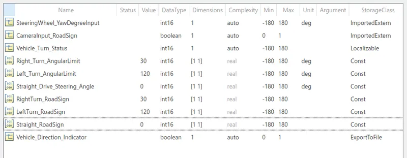
- For code generation, Storage class for Input signals: ImportedExtern; Storage class for Output signal: Export to File; Storage class for local signals: localizable; Storage class for calibration signals: Const.
- To Choose sample time for all signals as 0.01s
Process overflow:
Step 1:Simulink model creation-To create a simulink model for the "Vehicle Direction Detection ".
Step 2:Requiremet tagging-To tag the given two requirements to the simulink model "VVehicle Direction Detection "
Step 3:Simulink data dictionary creation-To create simulink data dictionary from the Signals & Calibration Data List.
Step 4:Auto code generation-To perform auto-code generation for the given simulink model.
Step5:Model advisory check: To perform the model advisory check .Select any one of the standards listed : ISO 25119(example)
Project Description:
Step 1:To create a simulink model for the "Vehicle Direction Detection ".
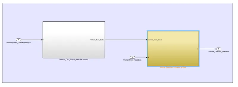
Based on the two Requirements 1 and 2 ,there are 2 seperate subsystems taken for model development.
In the subsystem 1:
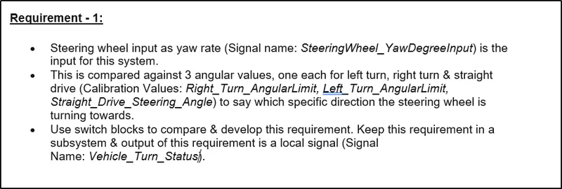
- Steering wheel input as yaw rate (Signal name: SteeringWheel_YawDegreeInput) is the input for this system.
- This input is compared against 3 angular values, one each for left turn, right turn & straight drive (Calibration Values: Right_Turn_AngularLimit, Left_Turn_AngularLimit, Straight_Drive_Steering_Angle) to determine which specific direction the steering wheel is turning towards and output of this subsystem is a local signal (Signal Name: Vehicle_Turn_Status).
In the subsystem 2:
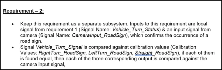
- Inputs to this requirement are local signal from subsystem 1 (Signal Name: Vehicle_Turn_Status) & another input signal from camera (Signal Name: CameraInput_RoadSign), which confirms the occurrence of a road sign.
- Next,Signal Vehicle_Turn_Signal is compared against calibration values (Calibration Values: RightTurn_RoadSign, LeftTurn_RoadSign, Straight_RoadSign), if each of them is found equal, then each of the three corresponding output is compared against the camera input signal,
- Using a logical operator block, only one among them is finally given as output signal (Signal Name: Vehicle_Direction_Indicator).
Simulink model for Vehicle Direction Detection :
Step 2:To tag the given two requirements to the simulink model of "Vehicle direction determination" .
Requirement1:

Requirement2:
Step 3:Simulink data dictionary creation-To create simulink data dictionary from the Signals & Calibration Data List.
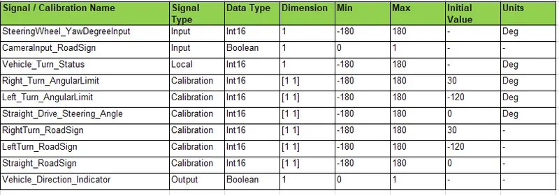
SLDD creation:
SLDD file
Step 4:Auto code generation-To perform auto-code generation for the given simulink model.
"Embedder coder" is used to perform code generation
Step1:Open APPS->Embedded coder -> Quick start
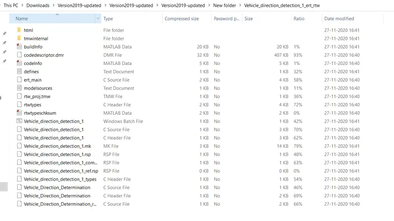
Step2: Auto code starts to generate ,save the report
Following files are saved after code generation:
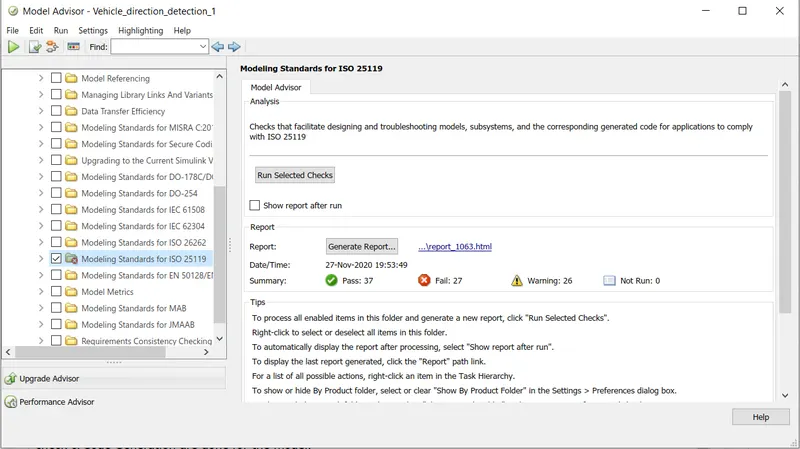
Step5:Model advisory check: Open the model advisory check tab .
Select any one of the standards listed : ISO 25119(example)
Run all the possible checks to perform the generation standardised of MBD model.
Result:
The simulink model for the Vehicle Direction Detection has been created as per requirements and all the MBD related process:Requirement Tagging & Traceability, SLDD creation, Configuration Parameter changes, Model Advisor check & Code Generation are done for the model.