Week-7 Challenge: DC Motor Control
CHALLENGE: DC Motor Control
AIM 1:
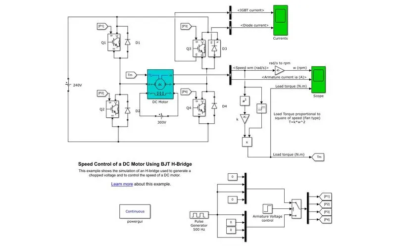
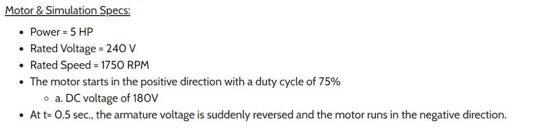
- Explain a MATLAB demo model named ‘Speed control of a DC motor using BJT H-bridge
- Comment on the armature current shoot-up from the scope results.
- Refer to the help section of ‘The Four-Quadrant Chopper DC Drive (DC7) block’. Compare it with the H-bridge model
THEORY:
Transistor:
It is a kind of semiconductor device that can be used to conduct or insulate electric current or voltage. A transistor basically acts as a switch and an amplifier. In simple words, we can say that a transistor is a miniature device that is used to control or regulate the flow of electronic signals.
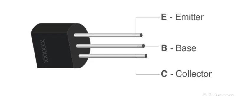
A transistor basically has 3 parts:
- base: Used to activate the transistor
- emitter: This is the positive lead of the transistor
- collector: This is the negative lead of the transistor
Based on how they are used, transistors can be classified into:
- BJT( Bipolar junction transistors)
- FET( Field effective Transistor)
Bipolar Junction Transistor
The three terminals of BJT are base, emitter, and collector. A very small current flowing between base and emitter can control a larger flow of current between the collector and emitter terminal.
BJTs are divided into 2:
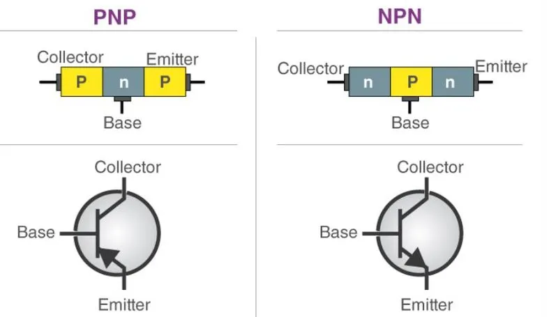
- npn
- pnp
P-N-P Transistor: It is a type of BJT where one n-type material is introduced or placed between two p-type materials. In such a configuration, the device will control the flow of current. PNP transistor consists of 2 crystal diodes that are connected in series. The right side and left side of the diodes are known as the collector-base diode and emitter-base diode respectively.
N-P-N Transistor: In this transistor, we will find one p-type material that is present between two n-type materials. N-P-N transistor is basically used to amplify weak signals to strong signals. In an NPN transistor, the electrons move from the emitter to the collector region resulting in the formation of current in the transistor. This transistor is widely used in the circuit.
BJT H bridge DC motor model
H-BRIDGE:
An H-bridge is a simple circuit that lets you control a DC motor to go backward or forward. The load is kept in the centre.
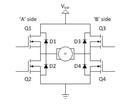
Though the load can in theory be anything you want, by far the most pervasive application if H-bridges is with a brushed DC or bipolar stepper motor (steppers need two H-bridges per motor) load.
Static Operation
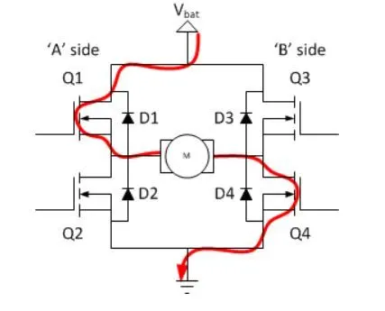
The basic operating mode of an H-bridge is fairly simple: if Q1 and Q4 are turned on, the left lead of the motor will be connected to the power supply, while the right lead is connected to the ground. Current starts flowing through the motor which energizes the motor in (let’s say) the forward direction and the motor shaft starts spinning.
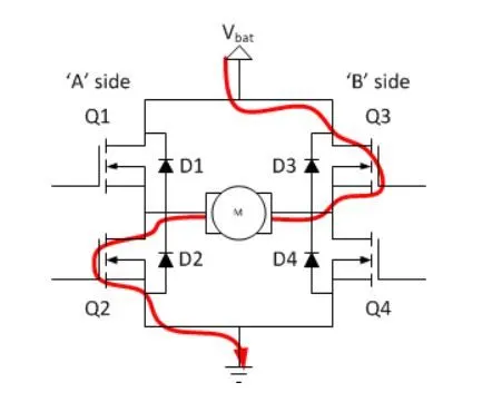
If Q2 and Q3 are turned on, the reverse will happen, the motor gets energized in the reverse direction, and the shaft will start spinning backward.
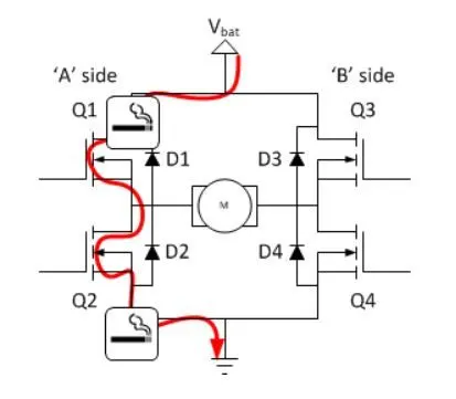
n a bridge, you should never ever close both Q1 and Q2 (or Q3 and Q4) at the same time. If you did that, you just have created a really low-resistance path between power and GND, effectively short-circuiting your power supply. This condition is called ‘shoot-through and is an almost guaranteed way to quickly destroy your bridge or something else in your circuit.
Main components used in the Model
1. Dc machine:
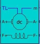
Implement wound-field or permanent magnet DC machine. access is provided to the field terminals (F+, F−) so that the machine model can be used as a shunt-connected or a series-connected DC machine. The torque applied to the shaft is provided at the Simulink® input TL.
2. IGBT Diode
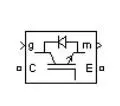
Implements ideal IGBT, GTO, or MOSFET and antiparallel diode
3. Diode
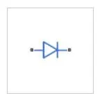
The Diode block can represent either a piecewise linear diode, an exponential diode, or a diode with a tabulated I-V curve.
WORKING OF THE MODE
Varying the speed of the DC motor:
In order to vary the speed of the DC motor, we have three ways:
- By varying the flux, and by varying the current through field winding.
- By varying the armature voltage, and the armature resistance.
- Through the supply voltage.
In order to vary the speed of the motor we have a pulse generator . This pulse generator is used to control the armature voltage which in turn controls the speed of the DC motor.
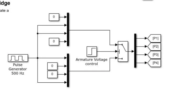
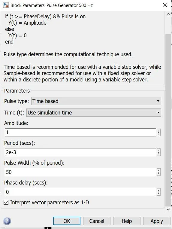
The method by which the width of the pulse is varied is called pulse width modulation(PWM). Pulse width modulation is the method of reducing the average power delivered by an electrical signal, by chopping it into discrete parts. The average value of voltage (and current) fed to the load is controlled by turning the switch between supply and load on and off at a fast rate.The main advantage of PWM is that power loss in the switching devices is very low. When a switch is off there is practically no current, and when it is on and power is being transferred to the load, there is almost no voltage drop across the switch.
The average output voltage is given by the equation:

It can be seen that pulse width is 50%, that is on time, and off time is the same, Vdc= Vs/2. Now if the pulse width is 25 %, Vdc will be 0.25 *Vs. So, as the pulse width varies, the voltage of the dc motor also varies.
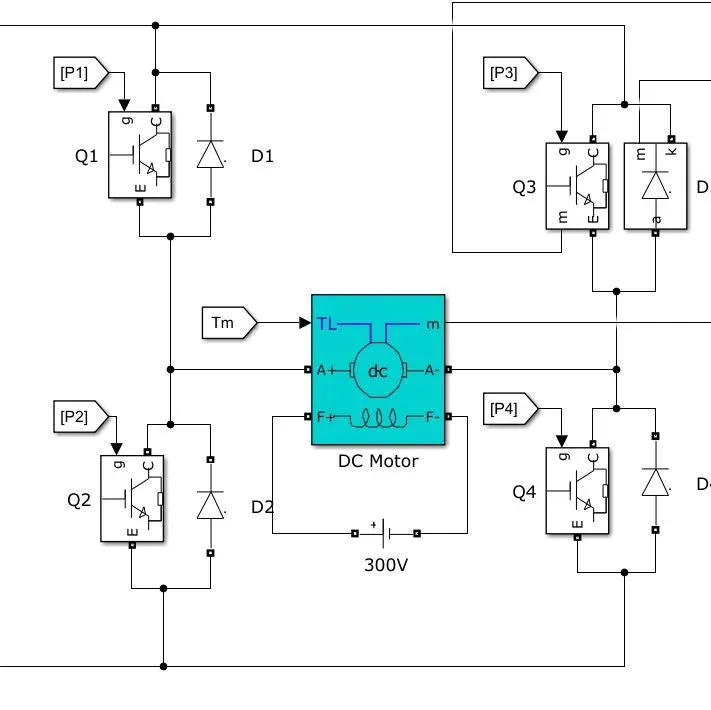
The given model consists of 4 transistors and 4 diodes. The transistors and named Q1, Q2, Q3 and Q4. The diodes are named D1, D2, D3, and D4. The connection is given as an H bridge.
Here the transistor acts as a switch. Q1 and Q 4 work together and Q2 and Q3 work together.
- When Q1 and Q4 are closed, the motor will spin in the anti-clockwise direction.
- When Q2 and Q3 are closed, the motor will spin in the clock wise direction.
The diodes D1 - D4 are used to protect the transistors , in case of some sudden surge in current or voltage. The diodes are reversed biased.
It should be made extremely careful not to close Q1 and Q2 or Q3 and Q4 together. If this happens, it provides a short circuit for the current flow and can cause good deal of damage to the components.
OUTPUT
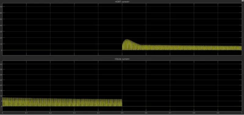
The scope named currents show:
- IGBT current
- Diode current
The second scope shows Dc motor characteristics :
- Armature current
- Load torque
- Speed of the rotor in RPM
GRAPHS
1. The graph shows IGBT current and Diode current
2. RPM, armature current and load torque is given in the next graph
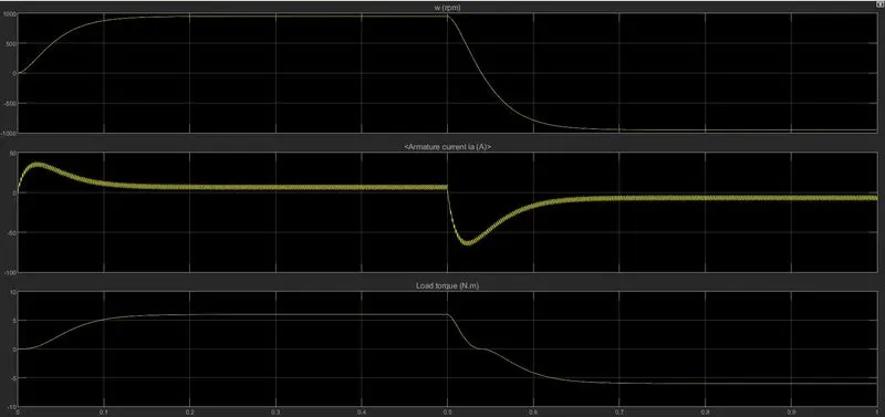
Consider the points:
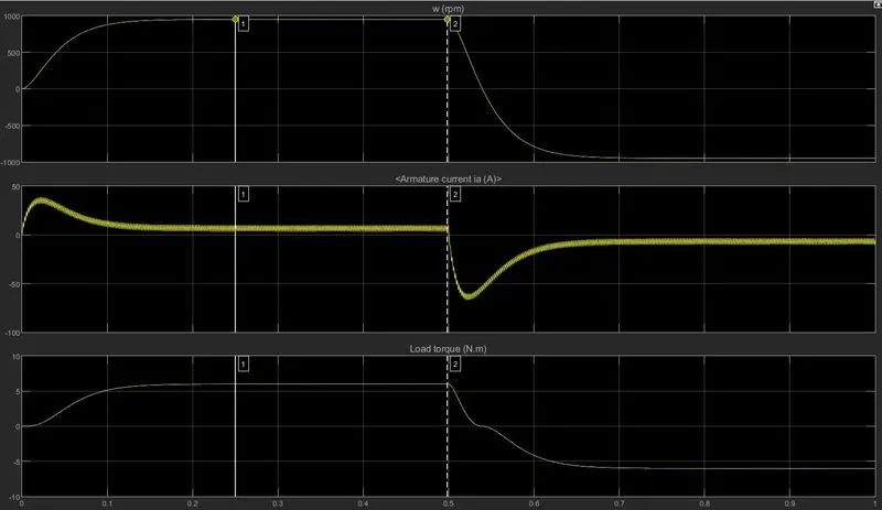
- From the first graph, it can be seen that the maximum value of RPM is from 0.2 - 0.5 sec. After the 0.5th sec, the RPM, current, and torque decreases
- There is a sudden decrease in the current value and then the value increases but remains below 0
- From the third graph, load torque is reducing when the RPM is reduced
NOW in order to reduce the shoot-up, we can alter the duty cycle. Changing the duty cycle from 75- 45 %, the variation can be seen in the given graph:
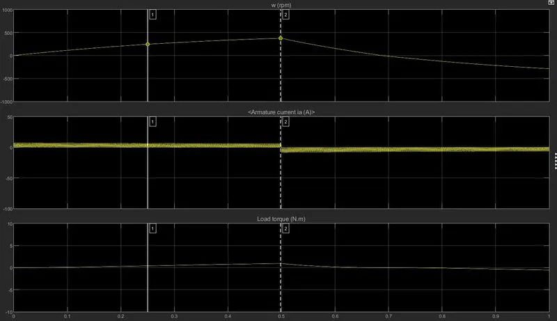
It can be observed that the shoot-up has been reduced drastically. But the Torque and the RPM values have been compromised to a great extent.
CONCLUSION:
It can be concluded from the graph that the shoot-up can be reduced significantly if the duty cycle is reduced. But this reduces the supply voltage which in turn reduces the speed and torque.
-------------------------------------------------------------------------------------------------------------------------------
COMPARISON OF FOUR-QUADRANT CHOPPER DC DRIVE WITH H-BRIDGE
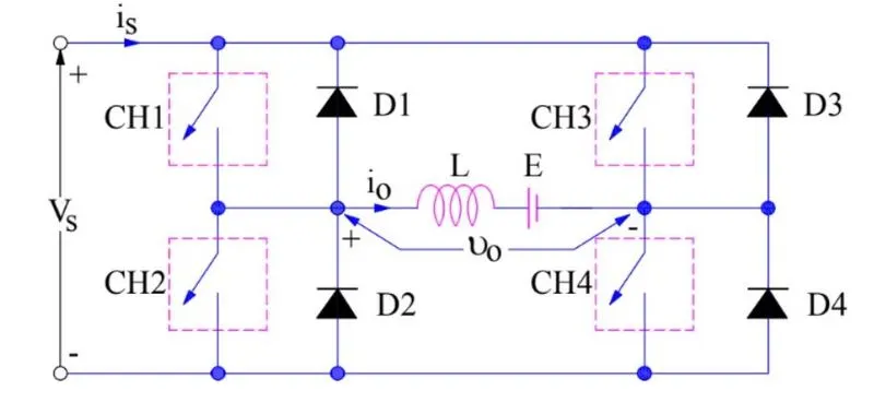
Before we go into the circuit, we will introduce what a 4 quadrant chopper is and it's working. The 4 quadrant chopper is given below. It consists of 4 switches (CH1 CH2 CH3 CH4) and 4 diodes( D1 D2 D3 D4). The 4 quadrant chopper works in 4 quadrants.
- Quadrant 1: forward motoring
- Quadrant 2: forward braking
- Quadrant 3: Reverse motoring
- Quadrant 4: Reverse braking
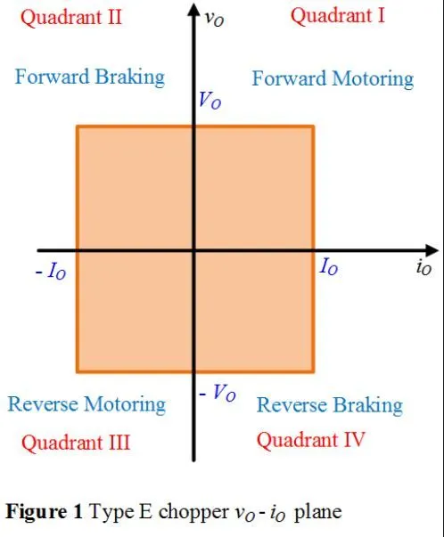
The four-quadrant operation can be explained :
1 . Forward Motoring:
- In this, switches CH1 and CH4 are closed. The supply voltage is Vs. As the switch is closed, the current will flow from CH1-Load-CH4. Now when CH1 is closed, the capacitor discharges and the current flows through the diode which is in forward biased.
- Since Io and Vo are positive, it is forward motoring.
2. Forward braking:
- When CH2 is ON, due to the presence of DC source E, the diode D4 gets forward biased. So from the graph it can be seen that the direction of current is opposite to the assumed direction
- When CH2 is OFF, output voltage Vo= Vl(stored in inductor)+E, since load voltage is greater than the supply voltage, the current is fed back to the source.
- Since the current is negative and voltage positive, it falls in the second quadrant.
3. Reverse motoring
- In this region, initially, CH3 and CH2 closed. We need to reverse the polarity of load supply E. CH2 and CH3 are closed, the current flowing through the load is opposite to the direction of the assumed flow. So current is negative. Also the voltage is negative.
- When CH3 is closed, the diode D4 becomes forward biased and current freewheels through CH2
- So in this quadrant, both are negative.
4. Reverse Braking
- CH4 is operated while keeping all other switches OFF
- when CH4 is on, due to DC source E, diode D2 becomes forward biased. So the current will flow in the same direction as that of the assumed direction.
- When CH4 is OFF, the output voltage is Vl+ E, but the output voltage is negative
Now consider the model:
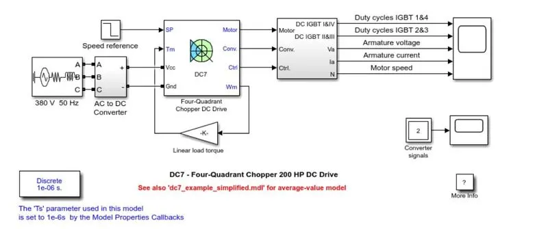
Model Description:
- Armature Voltage is provided by IGBT, controlled by PI regulators.
- The motor is separately excited by a 150 V DC source
- An AC-DC converter is employed, where a 515 V DC supply is obtained by rectification of a 380 V, 50 Hz supply
- In order to limit the DC voltage during dynamic braking mode, a braking chopper has been added between the rectifier and DC7 block.
- The first regulator used is the speed regulator, followed by the current regulator.
- The speed regulator outputs the armature current reference (in p.u.) used by the current controller in order to obtain the electromagnetic torque needed to reach the desired speed.
- The current regulator controls the armature current by computing the appropriate duty ratios of the 5 kHz pulses of the four IGBT devices (Pulse Width Modulation)
- The motor is coupled to a linear load, which means the speed is proportional to load.
Simulation Result
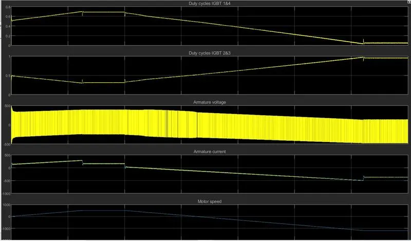
- The armature current follows the reference path with no shoot-up current.
- As the motor is coupled to a linear load, a mechanical torque is proportional to the speed of the motor.
COMPARISON WITH H BRIDGE
| H BRIDGE | 4 QUADRANT CHOPPER | |
| 1 |
Works in Open Loop system(Non-feedback mechanism). |
Works in closed-loop system(feedback mechanism). The armature voltage is controlled by PI regulators |
| 2 | The motor is not separately excited | The motor is separately excited with a constant 150 V DC field voltage source |
| 3 | It cannot work in regenerative mode. | It can work on all 4 quadrants. |
| 4 | We need to change the polarity in order to make the motor move forward or backward | We need to interrupt the signals. |
| 5 | Simulation is continuous | Simulation is discrete |
| 6 | The simulation takes more time and is less efficient | The simulation takes less time and its more efficient |
-------------------------------------------------------------------------------------------------------------------------------
AIM 2: Develop a 2-quadrant chopper & explain the working of the same with the relevant results
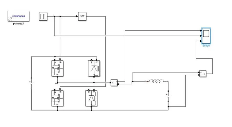
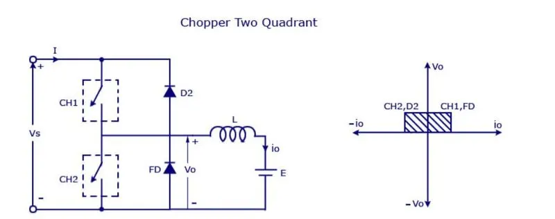
The above model is a 2nd -quadrant chopper modeled using Simulink software. The main components are :
- a pulse generator
- current measurement
- voltage measurement
- diode
- MOSFET
- scope
- AND operator
The working of the same is given below:
Type C chopper is obtained by connecting type –A and type –B choppers in parallel. We will always get a positive output voltage V0 as the freewheeling diode FD is present across the load. When the chopper is on the freewheeling diode starts conducting and the output voltage v0 will be equal to Vs. The direction of the load current i0 will be reversed. The current i0 will be flowing towards the source and it will be positive regardless of the chopper is on or the FD conducts. The load current will be negative if the chopper is or the diode D2 conducts. We can say the chopper and FD operate together as a type-A chopper in the first quadrant. In the second quadrant, the chopper and D2 will operate together as type –B chopper.
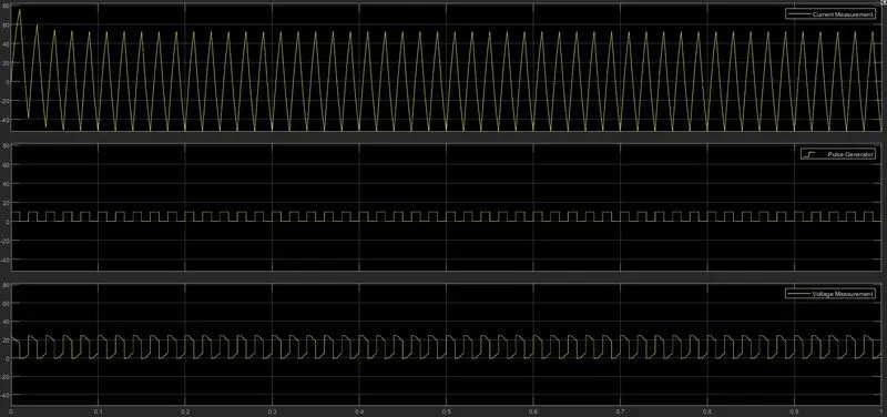
Output graph
zoomed :
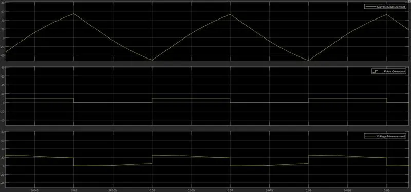
- it can be seen that voltage doesn't go to negative. The minimum value it attains is 0.
- The current, based on the switching action, varies from positive to negative.
--------------------------------------------------------------------------------------------------------------------------------------
AIM 3: Explain in a brief about operation of BLDC motor.
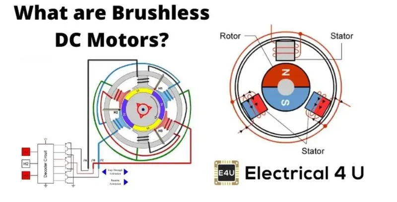
Brushless DC motors are common in industrial applications across the world. At the most basic level, there are brushed and brushless motors and there are DC and AC motors. Brushless DC motors, as you may imagine, do not contain brushes and use a DC current.
These types of motors are highly efficient in producing a large amount of torque over a vast speed range. In brushless motors, permanent magnets rotate around a fixed armature and overcome the problem of connecting current to the armature. Commutation with electronics has a large scope of capabilities and flexibility. They are known for smooth operation and holding torque when stationary.
A Brushless DC motor has only two basic parts: the rotor and the stator. The rotor is the rotating part and has rotor magnets whereas the stator is the stationary part and contains stator windings. In BLDC permanent magnets are attached to the rotor and move the electromagnets to the stator. The high-power transistors are used to activate electromagnets for the shaft turns. The controller performs power distribution by using a solid-state circuit.
Working Principle and Operation of BLDC Motor
BLDC motor works on a principle similar to that of a conventional DC motor, i.e., the Lorentz force law which states that whenever a current-carrying conductor placed in a magnetic field it experiences a force. As a consequence of reaction force, the magnet will experience an equal and opposite force. In the case BLDC motor, the current-carrying conductor is stationary while the permanent magnet moves.
When the stator coils are electrically switched by a supply source, it becomes an electromagnet and starts producing the uniform field in the air gap. Though the source of supply is DC, switching makes to generate an AC voltage waveform with a trapezoidal shape. Due to the force of interaction between the electromagnet stator and permanent magnet rotor, the rotor continues to rotate.
Consider the figure below in which the motor stator is excited based on different switching states. With the switching of windings as High and Low signals, corresponding winding energized as North and South poles. The permanent magnet rotor with North and South poles align with stator poles causing the motor to rotate.
Observe that the motor produces torque because of the development of attraction forces (when North-South or South-North alignment) and repulsion forces (when North-North or South-South alignment). In this way motor moves in a clockwise direction.
Advantages of Brushless DC Motor
The advantages of a BLDC motor are:
- Brushless motors are more efficient as their velocity is determined by the frequency at which current is supplied, not the voltage.
- As brushes are absent, the mechanical energy loss due to friction is less which enhanced efficiency.
- BLDC motor can operate at high speed under any condition.
- There is no sparking and much less noise during operation.
- More electromagnets could be used on the stator for more precise control.
- BLDC motors accelerate and decelerate easily as they are having low rotor inertia.
- It is a high-performance motor that provides large torque per cubic inch over a vast sped range.
- BLDC motors do not have brushes which make them more reliable, high life expectancies, and maintenance-free operation.
- There are no ionizing sparks from the commutator, and electromagnetic interference is also get reduced.
- Such motors cooled by conduction and no airflow are required for inside cooling.
Disadvantages of Brushless DC Motors
- BLDC motor cost more than a brushed DC motor.
- The limited high power could be supplied to the BLDC motor, otherwise, too much heat weakens the magnets and the insulation of winding may get damaged.