Week -2
PROJECT REPORT
AIM: Make a Simulink model of Doorbell using solenoid block with the following details:
In the above arrangement, when the switch is closed the electromagnet receives electrical power from the battery and pulls the metal arm to hit the bell producing sound.
Create a situation where the switch is closed for 2 seconds and then released. Observe the physical movement of the plunger.
REQUIREMENTS: Simulink and Simscape
THEORY:


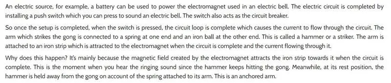
IMPORTANT BLOCKS USED
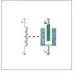
The Solenoid block represents the electrical characteristics and generated force for the solenoid.
The diagram shows the model of the bell that works with a solenoid
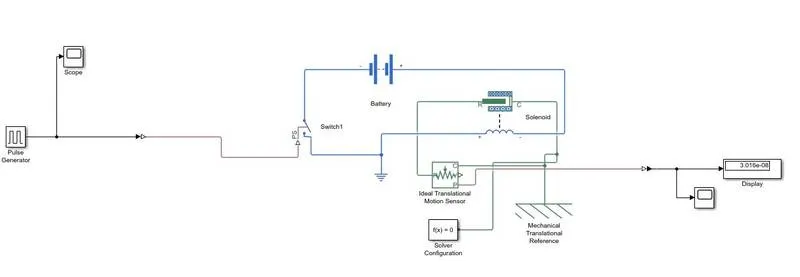 The given system has the following blocks:
- pulse generator
- scope
- switch
- battery
- solenoid
- ideal translational motion generator
- solver configuration
- mechanical translational reference
- display
EXPLANATION
- The solenoid block is obtained from the Simulink library.
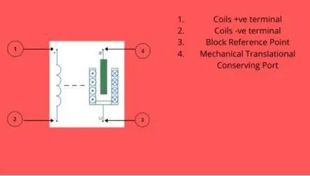
- The pulse generator gives the physical signal which determines the opening and closing of the switch.
- The solenoid is connected to the battery. When the current flows, the electromagnet is powerd and the plunger is attracted toward the bell.
- when the plunger strikes the bell, the current is cut off.
- The spring then returns the bell back to its first position which again completes the circuit. So current flows and magnetises , the again attracts the plunger to the bell
GRAPHS
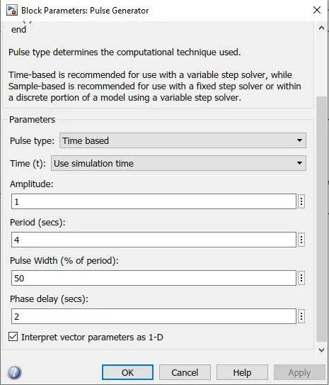
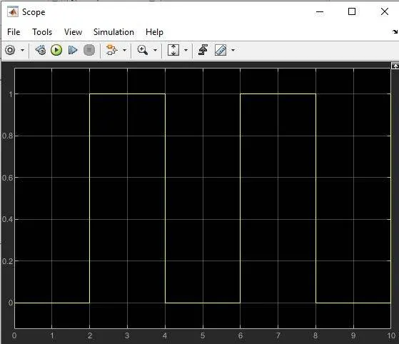
The first figure gives shows the initial condition of the pulse generator. The scope attached to it gives is the plot of the input signal.
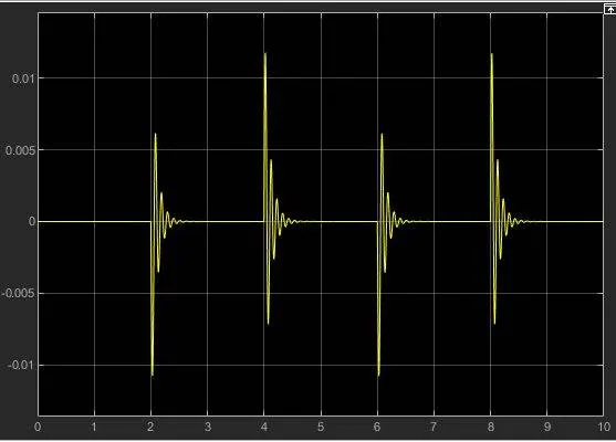
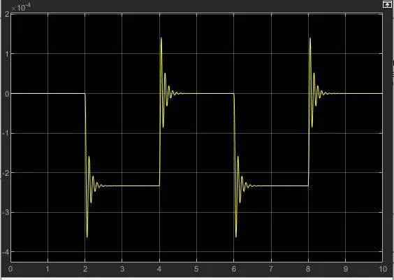
The first graph shows the plot of displacement of the plunger with time. The second plot shows the velocity of the plunger with time.
NOTE: By decreasing stiffness and increasing the damping coefficient, we can reduce the disturbance of the plot.
CONCLUSION
The system was modelled successfully and the graphs plotted.
_____________________________________________________________________________
AIM-2: Use a thermistor to sense the temperature of a heater & turn on or turn off the fan as per the below conditions:
Temperature source: 20 °C from 0 to 10 seconds, 27 °C from 10 to 30 seconds, 23 °C from 30 to 50 seconds
Fan conditions: ON if the temperature above 25 °C, OFF otherwise
REQUIREMENTS: Simulink software, Simcape
THEORY: A thermistor is a resistance thermometer, or a resistor whose resistance is dependent on temperature. The term is a combination of “thermal” and “resistor”. It is made of metallic oxides, pressed into a bead, disk, or cylindrical shape and then encapsulated with an impermeable material such as epoxy or glass.
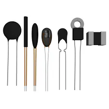
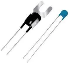
The symbol for the thermistor is given below:
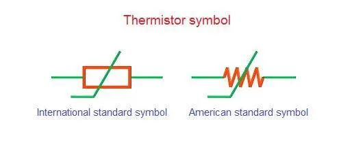
USES:
Thermistors have a variety of applications. They are widely used as a way to measure temperature as a thermistor thermometer in much different liquid and ambient air environments. Some of the most common uses of thermistors include:
- Digital thermometers (thermostats)
- Automotive applications (to measure oil and coolant temperatures in cars & trucks)
- Household appliances (like microwaves, fridges, and ovens)
- Circuit protection (i.e. surge protection)
- Rechargeable batteries (ensure the correct battery temperature is maintained)
- To measure the thermal conductivity of electrical material
- Useful in many basic electronic circuits
- Temperature compensation (i.e. maintain resistance to compensate for effects caused by changes in temperature in another part of the circuit)
- Used in Wheatstone circuits
WORKING PRINCIPLE:
The working principle of a thermistor is that its resistance is dependent on its temperature. We can measure the resistance of a thermistor using an ohmmeter.
if we know the exact relationship between how changes in the temperature will affect the resistance of the thermistor – then by measuring the thermistor’s resistance we can derive its temperature.
How much the resistance changes depends on the type of material used in the thermistor. The relationship between a thermistor’s temperature and resistance is non-linear.
There are two types of thermistors:
- Negative Temperature Coefficient (NTC) Thermistor
- Positive Temperature Coefficient (PTC) Thermistor
NTC Thermistor
In an NTC thermistor, when the temperature increases, resistance decreases. And when temperature decreases, resistance increases. Hence in an NTC thermistor temperature and resistance are inversely proportional. These are the most common type of thermistor.
The relationship between resistance and temperature in an NTC thermistor is governed by the following expression:

Where:
- RT is the resistance at temperature T (K)
- R0 is the resistance at temperature T0 (K)
- T0 is the reference temperature (normally 25oC)
- β is a constant, its value is dependant on the characteristics of the material. The nominal value is taken as 4000.
PTC Thermistor
A PTC thermistor has the reverse relationship between temperature and resistance. When temperature increases, the resistance increases.
And when temperature decreases, resistance decreases. Hence in a PTC thermistor temperature and resistance are directly proportional.
Although PTC thermistors are not as common as NTC thermistors, they are frequently used as a form of circuit protection. Similar to the function of fuses, PTC thermistors can act as a current-limiting device.
When current passes through a device it will cause a small amount of resistive heating. If the current is large enough to generate more heat than the device can lose to its surroundings then the device heats up.
In a PTC thermistor, this heating up will also cause its resistance will increase. This creates a self-reinforcing effect that drives the resistance upwards, therefore limiting the current. In this way, it acts as a current limiting device – protecting the circuit.
MAIN SIMSCAPE BLOCKS USED
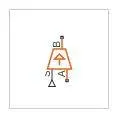
The Controlled Temperature Source block represents an ideal source of thermal energy that is powerful enough to maintain specified temperature difference across the source regardless of the heat flow consumed by the system.
2.DC motor
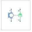
The DC Motor block represents the electrical and torque characteristics of a DC motor
3. Thermistor
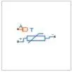
The Thermistor block represents an NTC thermistor using the B-parameter equation. The resistance at temperature T is
R=R0eB(1/T−1/T0)
RESULTS
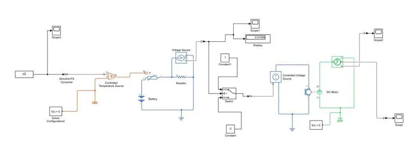
The above diagram shows the Simscape model of a thermistor that senses the temperature of a heater and switches on the fan based on some conditions.
The main components of the model are:
- scope
- solver configuration
- controlled temperature source
- thermistor
- battery
- resistor
- electrical reference
- voltage sensor
- ps-Simulink/Simulink-ps converters
- controlled voltage source
- thermal reference
- dc motor
- mechanical rotational reference
- constant blocks
EXPLANATION
- In order to model a cooling fan with a thermistor, the above following blocks are required.
- The thermistor is connected to a battery and resistor. To the resistor, a voltage sensor is connected.
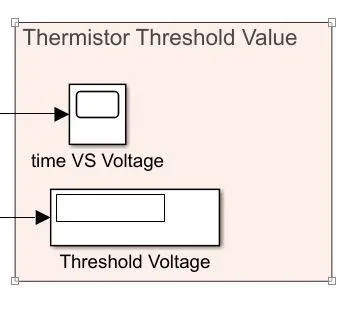
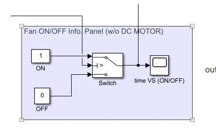
- The purpose of this voltage sensor is to decide the opening and closing of the switch which would run the fan.
- Now a controlled temperature source is connected to the thermistor. The Controlled Temperature Source block represents an ideal source of thermal energy that is powerful enough to maintain specified temperature difference across the source regardless of the heat flow consumed by the system.
- The signal input to the controlled temperature source block is given initially.
- The condition says that when the temperature is greater than 25, the switch should be in the on position. So we initially use a constant block with a temperature value of 298k. At this temperature, the voltage sensor senses a voltage across the resistor. This value is given as the threshold value for the switch. If the value is lesser, the switch remains in the off position else it goes to the on position.
- Since Simscape has no options for a fan, we use a dc motor.
- The dc motor is connected accordingly and it works as per the conditions.
- The motor is connected to an ideal rotational motion sensor which gives us the angular velocity too.
- With the help of scope, the results can be displayed graphically
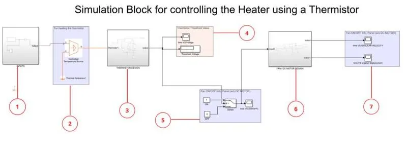

GRAPHS
1.The initial input to the controlled heat source can be given using a signal builder or plots can be extracted from an excel sheet and use 'from work space' option to obtain the block.
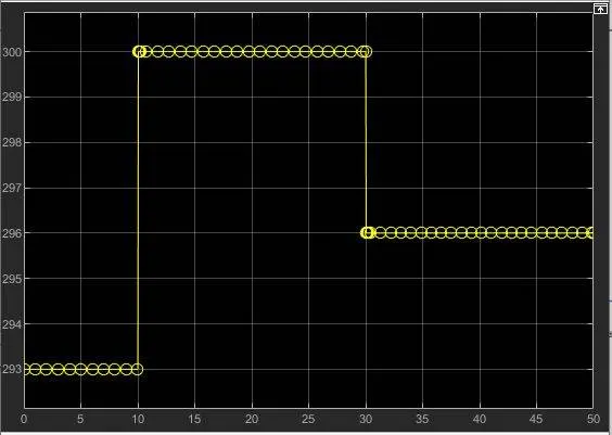
The given graph has a time range from 0 to 50. The temperature conditions are given as:
1. time=[0,10], temperature=293 K
2. time=[10,30], temperature=300 K
3. time=[30,50], temperature=296 K
2. The second graph is the graph showing the voltage across the resistor.
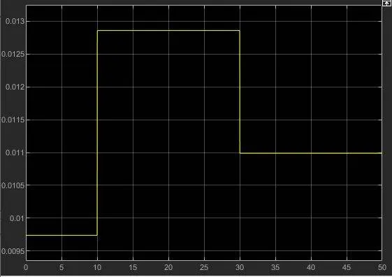
This graph shows how the voltage across the resistor is varying wrt to time. In the switch, we had given the threshold value as 0.01189. So only when the voltage value crosses that, the switch gets ON else it will be in the OFF position.
3.The angular displacement graph is shown below:
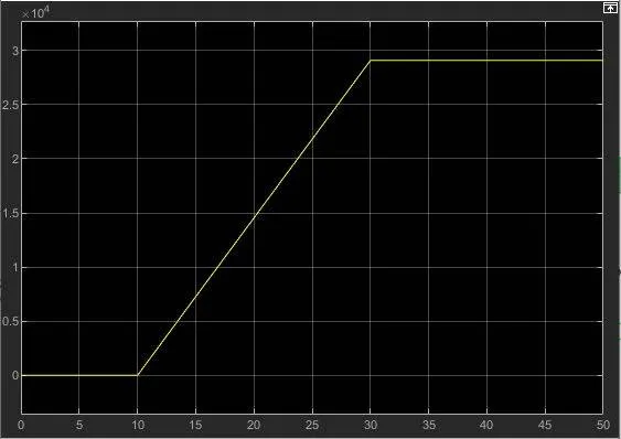
It can be observed that from 10-30 time interval, there is a linear increase. So the fan is running and velocity is increasing. After that, the value becomes constant.
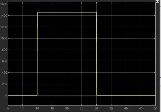
4. The last graph is the angular velocity graph
CONCLUSION
The system was successfully modelled and output was observed.