Week-7 Challenge: DC Motor Control
WEEK-7 CHALLENGE – DC MOTOR CONTROL
AIM:
- A. Explain a MATLAB demo model named ‘Speed control of a DC motor using BJT H-bridge.
- Comment on the armature current shoot-up from the scope results.
- Refer to the help section of ‘The Four-Quadrant Chopper DC Drive (DC7) block’. Compare it with the H-bridge model
- Develop a 2-quadrant chopper & explain the working of the same with the relevant results.
- Explain in a brief about operation of BLDC motor.
OBJECTIVE:
- To explain a MATLAB demo model named ‘Speed control of a DC motor using BJT H-bridge.
- To comment on the armature current shoot-up from the scope results.
- To refer to the help section of ‘The Four-Quadrant Chopper DC Drive (DC7) block’. Compare it with the H-bridge model
- To develop a 2-quadrant chopper & explain the working of the same with the relevant results.
- To explain in a brief about operation of BLDC motor.
QUESTION 1: A. Explain a MATLAB demo model named ‘Speed control of a DC motor using BJT H-bridge.
EXPLANATION:
Now opening H-bridge in MATLAB by typing power_Hbridge in command window we get the following Simulink model,
SIMULINK MODEL:
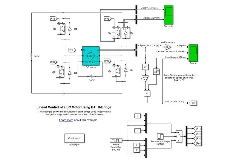
FIG1.SPEED CONTROL OF DC MOTOR USING BJT-H BRIDGE
EXPLANATION OF MODEL:
- It consists of 4 IGBT/Diode. at a time only two transistors are switched on simultaneously.
- Q1 and Q4 or Q2 and Q3
- When Q1 and Q4 are fired, a positive voltage is applied to the motor and D2 and D3 diode acts as a freewheeling diode when Q1 and Q4 are switched off. (FORWARD MOTORING)
- Similar things happen when Q2 and Q3 are fired, a negative voltage is applied to the motor. (REVERSE MOTORING)
- The pulse generator is connected to give an output to the forms of motor i.e., which IGBT will be ON i.e., communication channel.
- This whole circuit is connected to a 240 V DC supply and the motor is powered by 300V supply.
- The output of motor bus includes speed and armature current while load torque is calculated accordingly. (T_L is directly proportional to the square of the speed).
SCOPE RESULTS:
The below second graph the peak in the armature current when the mode is shifted from forward to reverse evident from the omega graph.
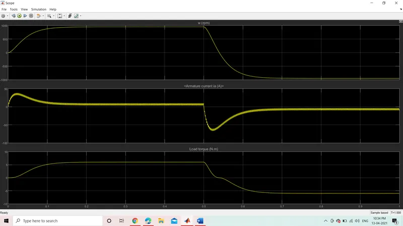
FIG.2 SCOPE RESULTS
- Initial spike of current is observed in the armature (1stShoot up)
- In motor, armature current (I) is given by: -
- I=(V-E)/R.
- Where, V is the voltage supplied, E is the back emf and R is the armature resistance.
- Thus, I depends upon E and R when V is kept constant. When the motor starts its speed remains zero i.e. E also remains zero (since, back emf is ∝ speed of the armature).
- Thus, initial starting armature current,
I=(V-0)/R= V/R. (as, E =0)
- Since, the armature resistance of a motor is very small, generally less than one ohm, therefore the starting current would be very large.
- As the motor speed increases, the back emf increases and the difference (V-E) goes on decreasing. This results in the gradual decrease of armature current until the motor attains its stable rated speed. Under this condition the armature current reaches its desired rated value.
- Another Shoot up can be observed in the Armature Current when motor changes direction from forward to reverse.
- In order to avoid this, Duty ratio can be optimized.
PARAMETERS OF PULSE GENERATOR:
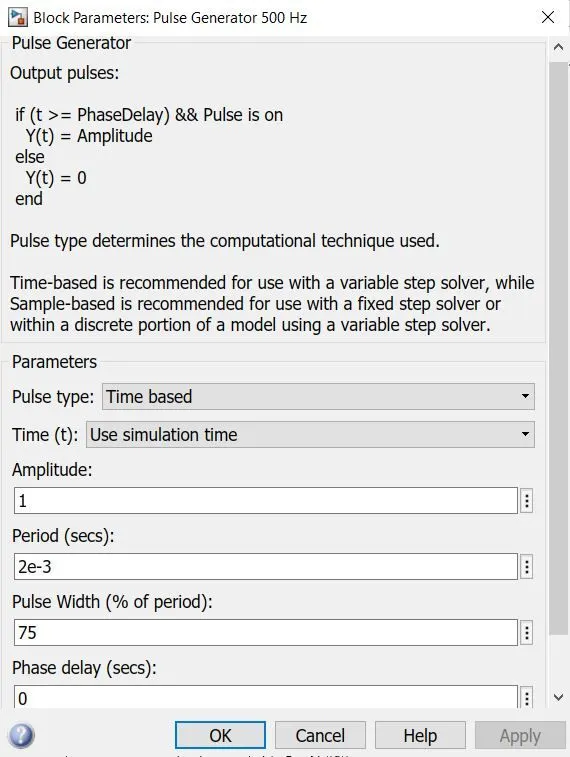
FIG 3. PULSE GENERATOR PARAMETER
SCOPE RESULTS:
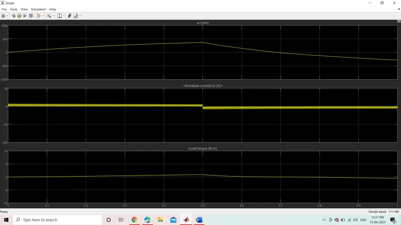
FIG.4 SCOPE RESULTS
In order to avoid this, Duty ratio can be optimized
Duty Ratio changed from 75% to 45 %.
- By reducing the Duty Ratio, Armature Current Shoot-Up can be completely optimized.
- But there will be considerable fall in the Load Torque and hence the Speed.
- No load Torque of the Motor has been reduced from 6 Nm to 2 Nm.
- No load Speed is reduced from 900 RPM to 400 RPM
RESULTS:
Reducing the Duty Ratio of the Power Modules, ultimately reduces the effect of shooting Armature current but reduces the Supply Voltage in to the Motors and results in the reduction of the Rated Speed and Torque of the Motor.
- Refer to the help section of ‘The Four-Quadrant Chopper DC Drive (DC7) block’. Compare it with the H-bridge model
EXPLANATION:
The Four-Quadrant Chopper DC Drive (DC7) block represents a four-quadrant, DC-supplied, chopper (or DC-DC PWM converter) drive for DC motors. This drive features closed-loop speed control with four-quadrant operation. The speed control loop outputs the reference armature current of the machine. Using a PI current controller, the chopper duty cycle corresponding to the commanded armature current is derived. This duty cycle is then compared with a sawtooth carrier signal to obtain the required PWM signals for the chopper.
The main advantage of this drive, compared with other DC drives, is that it can operate in all four quadrants (forward motoring, reverse regeneration, reverse motoring, and forward regeneration). In addition, due to the use of high switching frequency DC-DC converters, a lower armature current ripple (compared with thyristor-based DC drives) is obtained. However, four switching devices are required, which increases the complexity of the drive system.
The armature voltage is provided by an IGBT converter controlled by two PI regulators. The converter is fed by a 515 V DC bus obtained by rectification of a 380 V AC 50 Hz voltage source. In order to limit the DC bus voltage during dynamic braking mode, a braking chopper has been added between the diode rectifier and the DC7 block.
The first regulator is a speed regulator, followed by a current regulator. The speed regulator outputs the armature current reference used by the current controller in order to obtain the electromagnetic torque needed to reach the desired speed. The speed reference change rate follows acceleration and deceleration ramps in order to avoid sudden reference changes that could cause armature over-current and destabilize the system. The current regulator controls the armature current by computing the appropriate duty ratios of the 5 kHz pulses of the four IGBT devices (Pulse Width Modulation). For proper system behaviour, the instantaneous pulse values of IGBT devices 1 and 4 are opposite to those of IGBT devices 2 and 3. This generates the average armature voltage needed to obtain the desired armature current. In order to limit the amplitude of the current oscillations, a smoothing inductance is placed in series with the armature circuit.

FIG.5 FOUR QUADRANT CHOPPER CIRCUIT
Comparison of 4 Quadrant DC7 Chopper block vs. DC motor BJT – H Bridge Block-
- Regenerative braking is possible.
- The current values are chopped but not continuous hence simulation takes less time.
- It is widely used in Automobile to control DC Motor speed and direction.
- To change the direction pf motor current signals are interrupted with one another.
DC Motor BJT to H Bridge Block:
- Regenerative braking isn’t possible but dynamic braking can be achieved.
- The current values are continuous.
- It is widely used in Robotics & Electro – Mechanical Device to control D.C. Motor speed and direction.
- To change the direction of the motor only polarity of the current is changed.
QUESTION 2: Develop a 2-quadrant chopper & explain the working of the same with the relevant results.
EXPLANATION:
In this type of Chopper, the average voltage will be always positive but the average load current might be positive or negative. The two Switches CH1 and CH2 should not be turned on simultaneously as the combined action may cause a short circuit in supply lines. For regenerative braking and motoring these types of chopper configuration is used.
We will always get a positive output voltage V0 as the freewheeling diode FD is present across the load. When the chopper CH1 is on the current flows from source to load. The inductor stores energy. When Ch1 turn OFF the freewheeling diode starts conducting and the output voltage v0 will be equal to Vs. The direction of the load current i0 will be reversed. The current i0 will be flowing towards the source. The load current will be negative when the CH2 is on. The current completes its path through diode D2.
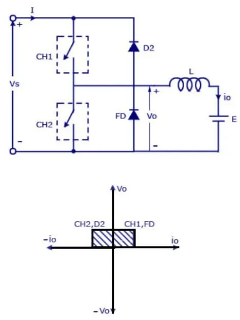
FIG.6 TWO- QUADRANT CHOPPER
QUESTION 3. Explain in a brief about operation of BLDC motor.
EXPLANATION:
BLDC Motor also known as Brushless DC Motor is a motor-operated without brushes to overcome certain difficulties. The basic difference between a brushed one and BLDC is operating with and without brushes.
A normal machine operates with brushes used to either collect or send current to the commutator. But due to the usage of brushes, sparking occurs at the brush location. As and when the rotor rotates it moves between brushes. At this time, the brushes undergo sparking during the rotation of the shaft. Due to this efficiency decrease and life expectancy are also reduced. To overcome these disadvantages, a BLDC is invented that performs a very smooth operation apart from the normal one. And due to the non-usage of the brushes sparking is also avoided. This increases the life expectancy and efficiency of the motor.
CONSTRUCTION
It consists of a frame in which the rotor and stator are fixed. The rotor is the rotating part and the stator is the stationary part. The frame is used to hold the inner peripherals and also used to protect them from the environment. The rotor is fixed with some permanent magnets and stator has some coils that act as an electromagnet. The number of poles depends upon the operational requirement. The stator has some slots in which the coils are placed. The number of coils to be placed depends upon the number of poles. Depending upon the requirement these coils are energized. The stator winding of this type of motor is shown in the figure below.
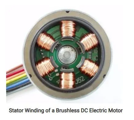
The difference between a permanent magnet and an electromagnet is the permanent magnet has its property inbuilt. But the electromagnet requires some current to pass through the coil to get energized.
WORKING OF BLDC MOTOR:
The BLDC operates on the same law as of a regular type. This type requires some coils to be energized in order to make the rotor rotate. The coils placed in the stator slots are named as A, B, and C. When the coil A is energized by a DC supply, it gets excited and attracts the rotor permanent magnet. Similarly, when the coil B is energized rotor permanent magnet is attracted this continues when the coil C is also energized. After the coil C is energized, the coil A is again energized but with negative polarity. This continues with the remaining coils as well with negative polarity. This cycle continues alternately and the rotor continuously rotates.
But there is a problem of developing the low power output. This can be overcome by connecting the free ends of two coils together i.e., A and B. This produces greater power output as the coils energize double the field and pull the rotor permanent magnets along with them. This way a greater output can be achieved.
The problem with the BLDC type is that which coil to energize first. It can be known by finding the position of the rotor coils. This position can be known by using a controller. The controller helps in energizing the coil after receiving the position from the sensor.
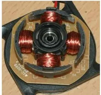
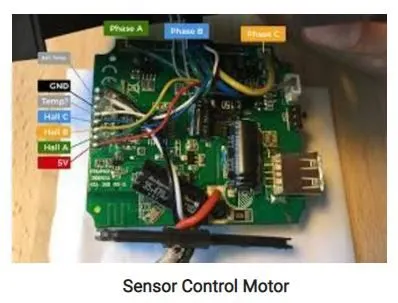
A Hall Effect sensor is used for the detection of the position of the coils. The sensor gives this information to the controller. The controller which in turn gives a command for which coil to be energized. The hall effect sensor is shown in the figure below.
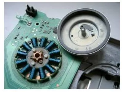
Hall Effect Sensor
TYPES
There are two types of BLDC. They are IN-type and Out-type.
It depends upon the construction i.e., if the rotor is made to rotate outside then it is Out-type. If the rotor is made to rotate inside then it is considered as IN-type. The most common type used is of Out-type.
Controlling Speed of BLDC Motor
The controlling of the speed of this type is quite as this type includes a controller. The speed control can be possible by adjusting the voltage. Depending upon the amount of voltage supplied to energize the coils the speed can be varied. The voltage supplied to the coils is reduced in order to decrease the speed of the motor.
Advantages
- Highly reliable
- Smoother operation
- High power output
- Can be used for higher speed applications
- No brush is required
- No sparking
- Light in weight
- Less noise
Disadvantages
- Complex operation
- Requires maintenance
- A controller is required
- Costly
- Sensors are required
Applications
It finds its application in small toys, drills machines, AC, PC, servers, trimmers, ventilation fan, air cleaners, projectors, power supply, CCTV, DVR, mixer grinders, hairdryers, and electronic cars or bikes.