Week -2
WEEK:2 - CHALLENGE
AIM:
To stimulate the given Simulink model.
OBJECTIVE:
To make a Simulink model of doorbell using solenoid block.
To make a Simulink model using a thermistor to sense the temperature of a heater & turn on or turn off the fan.
GOVERNING DIAGRAMS:
For Solenoid:
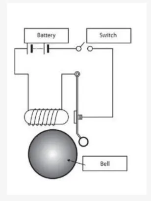
Basic Components used to generate a simple doorbell circuit are:
1.Solenoid
2.Battery
3.Switch
4.A bell with plunger.
EXPLANATION:
A solenoid is a common term for a wire coil used as an electromagnet. It also applies to any system that uses a solenoid to transform electric energy into mechanical energy. The system generates a magnetic field from electric current and produces linear motion using the magnetic field.
WORKING OF SOLENOID:
A solenoid is a coil of wire tied across a piston, mostly made of iron, in the form of a corkscrew.
Like with all electromagnets, when an electric current pass via the wire a magnetic field is generated.
The advantage of electromagnets over permanent magnetic material is that they have been turned on and off by adding or removing the electrical field, making them effective as controls and switches, enabling them to be automated.
The magnetic field of an activated solenoid has both positive and negative poles that attract or repel sensitive material to the magnets.
The electrical force causes the piston to shift either forward or backward inside a solenoid that’s how a solenoid coil creates motion.
Consider a solenoid of length is such that it is large as compared to its radius. Here the wire is wrapped with a very small gap between any two turns in the shape of the helix. The wires are also enamelled, rendering them insulated from one another. As a consequence, one can take every turn as a closed circular loop. Thus, created magnetic field is equal to that formed by a circular loop and the total magnetic field created by the solenoid can be specified as the sum of vector force generated by every such turn. The lines of magnetic fields generated inside a finite solenoid are shown in the figure below.
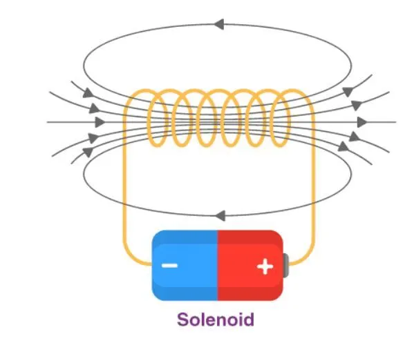
From the above figure, we can see that the magnetic field within the solenoid is constant and runs along the solenoid axis. The field at the outside immediately to the solenoid at every point is very low and the field lines can’t be seen at the close surrounding. It’s necessary to note that at every place the field within is parallel to its axis.
From the Law of the Ampere, the magnetic force created by a solenoid can be described as,
F=μ0nI
Where,
n = number of turns of the wire per unit length
I = current flowing through the wire
The direction is given using the right-hand thumb rule.
FOR THERMISTOR:
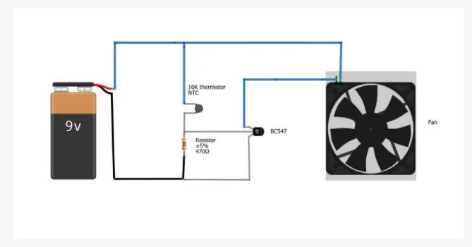
Basic Components used to generate a simple cooling fan circuit are:
1.Battery
2.Thermistor
3.Fan
4.Transistor
5.Resistor
A thermistor is a resistance thermometer, or a resistor whose resistance is dependent on temperature. The term is a combination of “thermal” and “resistor”. It is made of metallic oxides, pressed into a bead, disk, or cylindrical shape and then encapsulated with an impermeable material such as epoxy or glass.
There are two types of thermistors: Negative Temperature Coefficient (NTC) and Positive Temperature Coefficient (PTC). With an NTC thermistor, when the temperature increases, resistance decreases. Conversely, when temperature decreases, resistance increases. This type of thermistor is used the most.
A PTC thermistor works a little differently. When temperature increases, the resistance increases, and when temperature decreases, resistance decreases. This type of thermistor is generally used as a fuse.
Typically, a thermistor achieves high precision within a limited temperature range of about 50ºC around the target temperature. This range is dependent on the base resistance.
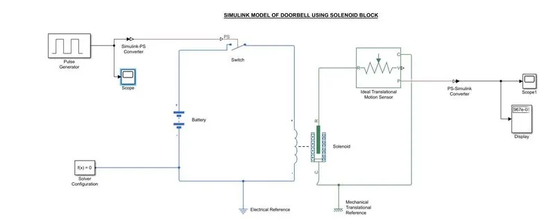
SIMULINK MODEL OF DOOR BELL:
EXPLANATION:
- From the above governing circuit of a door bell, we know that we need a switch, solenoid, battery and a plunger.
- So, in order to get all these components into a Simulink model we have to taken blocks that perform same action what the above devices perform.
- Now we can select the correct solenoid and battery blocks from the library browser.
- Then, drag the signals into a solenoid block and battery block are connected to each two terminals.
- A switch block placed in between the battery block and the solenoid block.
- Now for the switch to operate we need to provide a physical signal through PS port in the Switch block. The provided physical signal should be greater than the threshold of the switch, for the switch being closed, or else it will be open.
- Now this whole battery, switch and solenoid path is connected to an electrical reference block which represents earthing the circuit. This electrical reference block should be connected with negative port of the battery block.
- Then in the solenoid block R and C are two variables which represent plunger and fixed point respectively.
- Now this R is connected to a R of Ideal Translation Motion Sensor Block which senses the position of the plunger in the Solenoid block and gives the output.
- Now in Ideal Translation Motion Sensor Block the outputs are given as V and P which represent the velocity and position of the plunger. Since we are only interested in knowing the change in position of the plunger, so we only result from P output.
- Now C in the ideal translation motion sensor block is a mechanical translation conserving port, which means that the mechanical process starts from R and ends at C and again it starts R and the cycle goes on.
- So, C of the ideal translation motion sensor block is connected to a mechanical reference which represents a fixed point where it is rigidly clamped in real time.
- Similarly, C of solenoid block is also connected to the same mechanical translation reference as fixed point for the solenoid.
- Since we position of the plunger as output from ideal translation motion sensor block, we have connected port P to a PS – Simulink converter where the physical values from port P are converted into Simulink value, and then this PS Simulink converter is connected to scope block which will generate a graph for change in position of plunger from port P of ideal translation motion sensor block.
- Now to provide a physical signal for operating the switch, we have used a pulse generator block which generates a continuous square pulse.
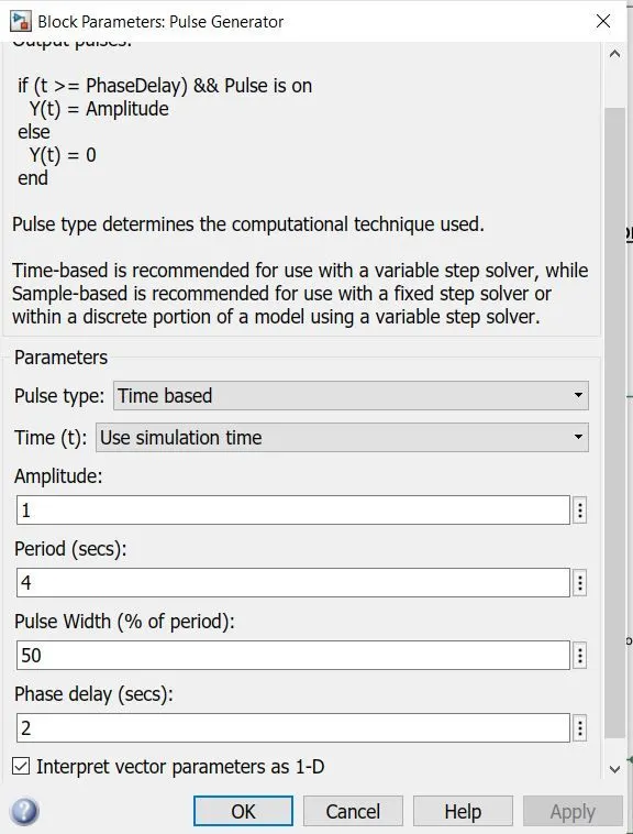
16.From the above figure we can observe that we have taken we have given period value as 4 pulse width as 50 phase delay as 2 and amplitude by default is 1 we have not changed it. This means that initially the pulse will be zero, since we have given phase delay of 2 so till 2 sec the pulse will be zero and at 2 secs the pulse will start from zero to 1 since we have given amplitude as 1 only then it will again come down to zero at 4th second and then it will at zero for next 2 secs thus completing the period of 4 seconds.
17.From starting to ending of the pulse it will take 4 secs of time period in which only for 2 secs the amplitude will be one and for rest of time it will be zero. So, after these 4 secs period again the pulse will be generated and thus cycle continues.
18.To this pulse generator block a scope block is connected to see how the pulse is generated.
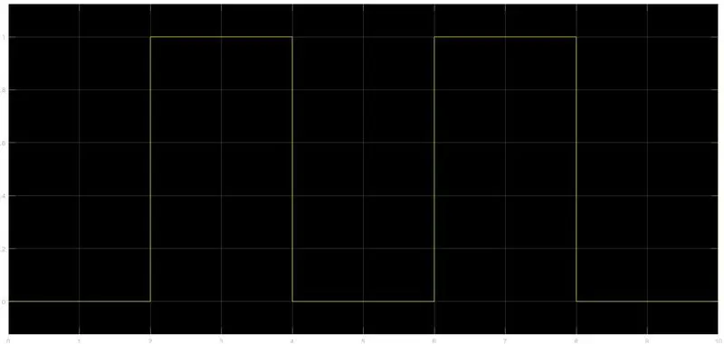
19. The above figure is obtained by running the Simulink model and double clicking on the scope1 block. This figure shows how the pulse is generated and in this figure the x axis represents the time and y axis represents the amplitude. As mentioned in the point no.18 the pulse has started after 2 seconds, then for next two seconds the pulse is again zero. The pulse is starting from 2 seconds and ending at 6 seconds which nothing but a time period of two seconds.
20. Thus, this represents that when amplitude is one, the switch will be closed and when it is zero the switch will open. Since our objective is only to see the change in position of plunger when switch s closed for 2 secs so, we have the amplitude as 1 for 2 secs in the pulse generator by making the pulse width half of the period in the inputs for pulse generator block.
21. Since the pulse that is coming from pulse generator block is a Simulink value, so to convert this value into a physical value we have used Simulink PS convertor block since switch only takes physical value as inputs.
22. As mentioned above the port P od ideal translation motion sensor block is connected to another scope block, and a solver configuration block is also connected, to generate equation and solves the whole model internally to give the results of the whole Simulink model as output.
23. Now the run the model and double click on the scope block which is connected to ideal translation motion sensor block to get the results.
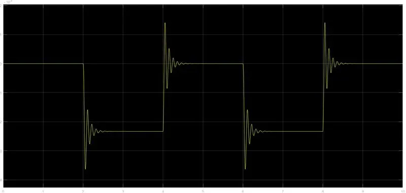
24.We will get above graph as the result when we double click on the scope block. Here x axis represents the time in seconds and y axis represents position of plunger in mm.
25.From the above figure we can observe that the initial position of the plunger is at 5 as from the pulse generator block, a pulse generated at 2, so in the position of the plunger is also changing at time 2 seconds and time till which the pulse amplitude is 1 till that time the plunger is also at same position after the change from initial position.
26.Again, as the amplitude of the pulse becomes zero, the plunger returns to its initial position back again and as the pulse cycle goes on, plunger also changes its position and comes back to its initial position.
27.We can also observe that when there is a change in the position of the plunger, there are some waves forms at the start of changes in position. This is due to recoil of the spring, each time when the plunger is moving. So to reduce this, in the solenoid block we can reduce the spring constant and increase the damping coefficient. This will reduce the waves that are being formed and we will get a smooth graph
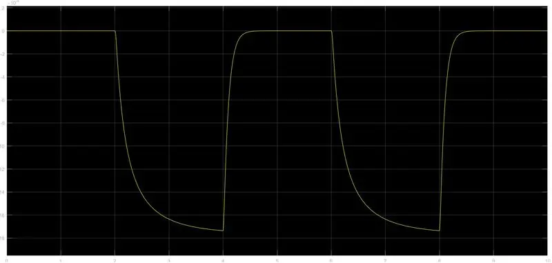
28.The above figure is a smoother graph than previous one. This is done by changing the values of spring constant and damping in the solenoid block.
SIMULINK MODEL OF THERMISTOR:
EXPLANATION:
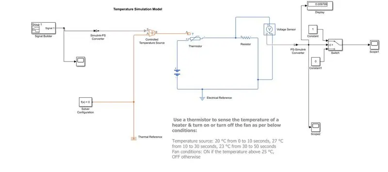
- To create a simple cooling fan model using thermistor we need a thermistor, battery, resistor, voltmeter, a logical switch which are basic components of the circuit we need in the Simulink model.
- First to represent a thermistor, a thermistor block is taken and placed in the model. Now to represent a battery a battery block is taken and the positive port of this block is connected to positive port of the thermistor block.
- Now to represent a resistor, a resistor block is taken from the library browser and its positive port is connected to negative port of the thermistor block. The negative port of resistor block is connected to the negative port of the battery block. Now a electrical reference block is connected near the negative terminal of the battery block which represents the earthing of the real time circuit.
- Now to represent a voltmeter a voltage sensor block is connected parallel to the resistor block because to measure to voltage across a component, voltmeter should be always connected parallel to that component.
- Thus, we have completed our simple circuit model, but we need some physical quantities to as signal for thermistor to work.
- In this case we need the fan to get on and off at different temperatures. So, to provide temperature, we have used controlled temperature source block which only gives a specified temperature as output even though heat flow is more.
- Now to give different temperatures to this controlled temperature source block we need to send temperature signals. To send these signals we have used a signal builder block which allows use to send any type of signals as inputs.
- We have to double click on the signal builder block to set the signal according to our requirement.
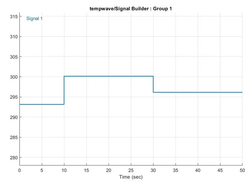
9.Above figure shows how the signal are set in the signal builder block. As this dialogue box opens, first we have to click on the signal at the top and then select new then select custom option. Now we can figure out it manually by adjusting the time limits and y axis limits.
10.We can see in the figure that how different temperature are given at different time. So, thus we have created our signals and before connecting it to the controlled temperature source block, we have to convert these signals into a physical value. So, to do this we have used a Simulink- PS Converter block.
11.So now the port B of controlled temperature source block is connected to port A of the thermistor block and port A of Controlled temperature source block is connected to a thermal reference block. In controlled temperature source block a positive temperature difference causes the temperature at port B to be greater than the temperature at port A.
12.Now the output of the voltage sensor block is connected to scope block first, and before connecting to the scope block a PS-Simulink convertor is used to convert physical value to Simulink values.
13.Now when we run the simulation and double click on the scope block, we will get the following graph.
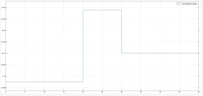
14.From the above figure we can see that how voltage is changing with change in temperature. Using this information, we can set conditions for fan on and off.
15.If we observe the graph, we notice that from time 0 to 10 seconds when temperature is 293.15K, voltage in-between the limits 0.0095 and 0.01 and from time 10 to 30 seconds when temperature is 300K, voltage in-between 0.0125 and 0.013 and from time 30 to 50 seconds when temp – 296K the voltage is 0.011.
16.As mentioned in the objective fan should be on when temperature is more than 25-degree Celsius, from the above graph when voltage is more than 0.011 the fan should on and when voltage is below 0.011 fan should be off.
17.The centre port of switch block is connected to output of PS- Simulink converter which gives the voltage values. The top port of switch block is connected to another constant block of value 0.
18.Now the output of switch block is connected to another scope to get the results.
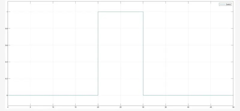
19.Double click the scope block we can observe the above graph. Here we can clearly see that when temperature is 300K the fan is on at remaining temperatures the fan is off.
CONCLUSIONS:
Thus, the stimulate the both Simulink model has to be done successfully.
REFERENCES: