Week-7 Challenge: DC Motor Control
- Run MATLAB demo ‘Speed control of a DC motor using BJT H-bridge’. Modify the model such that armature current doesn’t shoot up when motor changes direction from forward to reverse.
- Refer to help section of ‘The Four-Quadrant Chopper DC Drive (DC7) block’. Compare it with the H-bridge model.
- Make a suitable EV model using DC7 block and make result report.
- Explain in a brief about operation of BLDC motor.
ANSWERS
- To run MATLAB demo ‘Speed control of a DC motor using BJT H-bridge’. Modify the model such that armature current doesn’t shoot up when motor changes direction from forward to reverse.
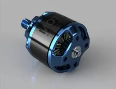
DC motor
Electric motors turn electricity into motion by exploiting electromagnetic induction. A simple direct current (DC) motor is illustrated below. The motor features a permanent horseshoe magnet (called the stator because it's fixed in place) and an turning coil of wire called an armature (or rotor, because it rotates).
BJT H-bridge
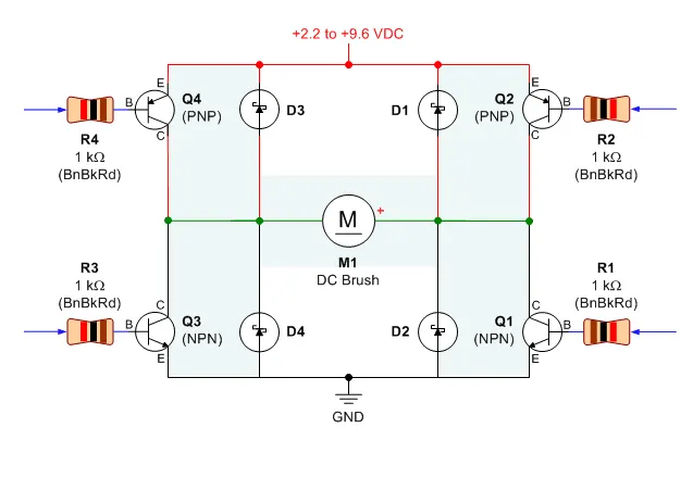
An H-bridge is an electronic circuit that switches the polarity of a voltage applied to a load. These circuits are often used in robotics and other applications to allow DC motors to run forwards or backwards. ... In particular, a bipolar stepper motor is almost always driven by a motor controller containing two H bridges.
The Bipolar Junction Transistor (BJT) when used for power switching applications, operates as an IGBT. When it is conducting (BJT operating in the saturated region), a forward voltage Vf is developed between collector and emitter (in the range of 1 V). Therefore, the IGBT block can be used to model the BJT device.
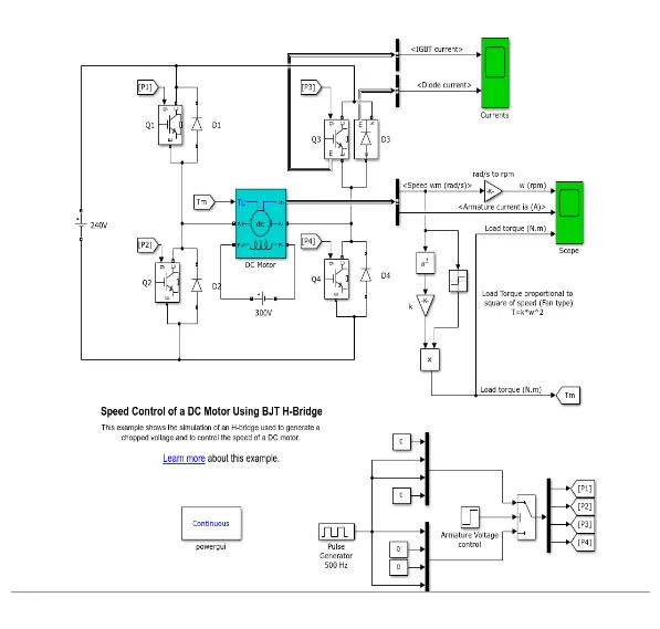
The IGBT block does not simulate the gate current controlling the BJT or IGBT. The switch is controlled by a Simulink® signal (1/0). The DC motor uses the preset model (5 HP 24V 1750 rpm). It simulates a fan type load (where Load torque is proportional to square of speed). The armature mean voltage can be varied from 0 to 240 V when the duty cycle (specified in the Pulse Generator block) is varied from 0 to 100%.
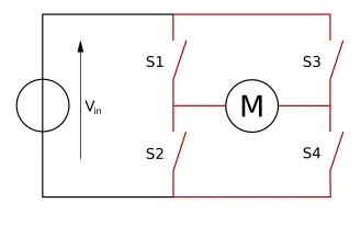
The H-bridge consists of four BJT/Diode pairs (BJT simulated by IGBT models). Two transistors are switched simultaneously: Q1 and Q4 or Q2 and Q3. When Q1 and Q4 are fired, a positive voltage is applied to the motor and diodes D2-D3 operate as free-wheeling diodes when Q1 and Q4 are switched off. When Q2 and Q3 are fired, a negative voltage is applied to the motor and diodes D1-D4 operate as free-wheeling diodes when Q2 and Q3 are switched off.
Speed control of a DC motor using BJT H-bridge in MATLAB
The speed control of a DC motor using H-Bridge model fig. is below,DC voltage source of 240v is circuit with DC motor and BJT switches in H shape and Output scope show the plots of speed , Armature current and torque of the motor.At the right bottom it have control blocks pulse generator, step and conditional switch , output of this are given to the each BJT switches.
Run the model without any changes .Observe the plot of speed,armature current and torque of the motor. Duty cycle is 75% and internal resistance of the IGBT switch is 0.001 ohms.
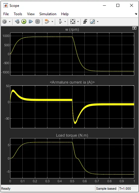
There are two methods for control of armature current doesn’t shoot up when motor changes direction from forward to reverse.
- Duty cycle
- Internal resistance of Switches
METHOD 1
DUTY CYCLE
A duty cycle or power cycle is the fraction of one period in which a signal or system is active. Duty cycle is commonly expressed as a percentage or a ratio. A period is the time it takes for a signal to complete an on-and-off cycle.
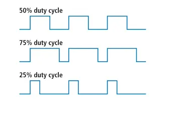
Hence by decreasing the duty cycle , control of armature current doesn’t shoot up when motor changes direction from forward to reverse is obtained. By using power electronics it can be change nothing but the control elements .
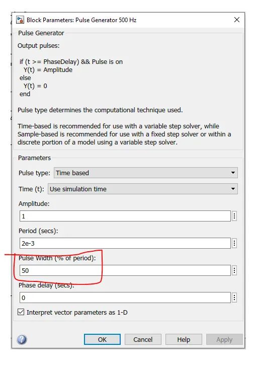
Go to the control blocks click on the pulse generator and change the duty cycle of the pulse generator.You can see the below fig. of the change of the duty cycle.I had changed to Duty cycle= 50%.
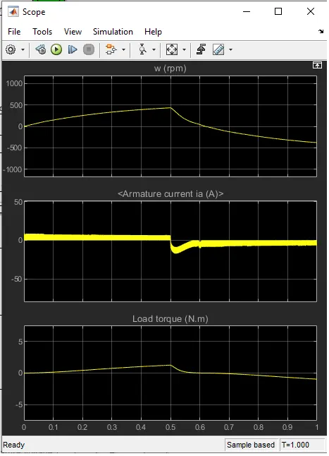
Run the model after changing the duty cycle , if we exactly observe the plot of armature current still it is shoot up when the motor changes its direction forward to reverse. So duty cycle should be below the 50% .
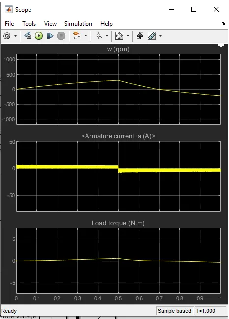
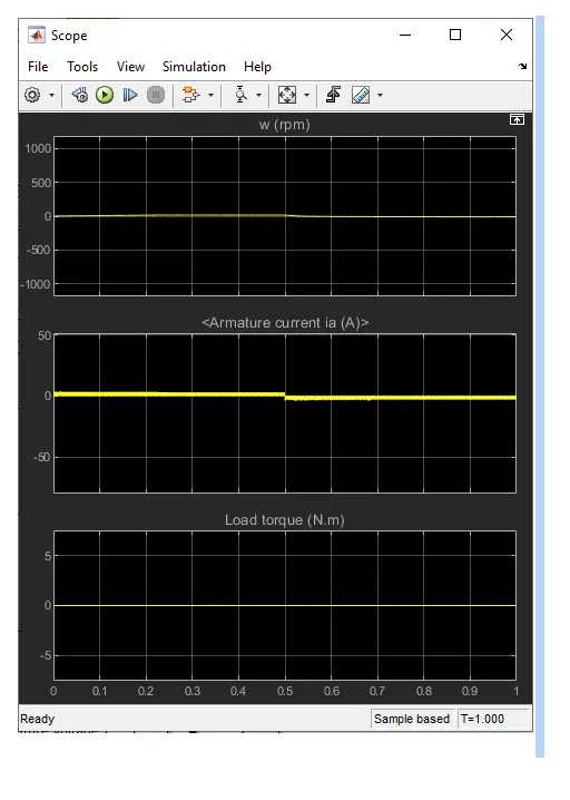
Change the duty cycle of the pulse generator to 40% and run the model ,observe the resultant graphs of speed ,armature current and tor que of the DC motor.
Thus output graph of the armature current of the motor is no more shoot up when the motor change the direction forward to reverse .
Again Change the duty cycle of the pulse generator to 20% and run the model ,observe the resultant graphs of speed ,armature current and torque of the DC motor.
Thus output graph of the armature current of the motor is no more shoot up when the motor change the direction forward to reverse .
METHOD 2
General method to oppose the current is increase the strength of resistance
Here in the given model the speed control of the DC motor IGBT switches are used ,so the internal resistance of each switch must be increase .
Change the internal resistance of the switch Ron=10 ohms as shown in the below fig.
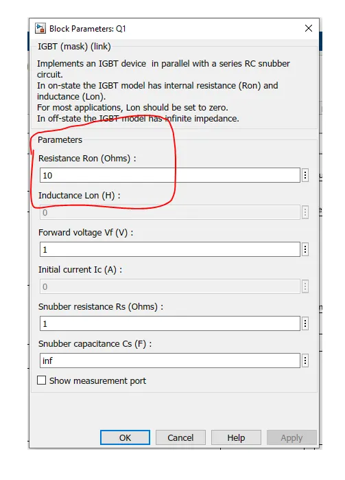
Run the model after changing the resistance of the switch and observe the graphs of armature current there is no shoot up when the motor changes the direction forward to reverse.
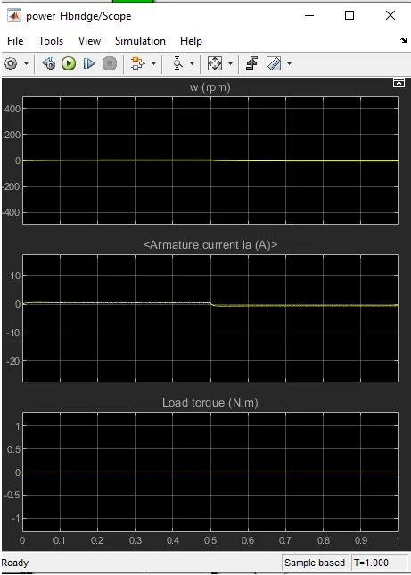
Hence practically the internal resistance of the switch can be changed at manufacture time only once the switch is designed , it cannot be changed .So the method 1 using Duty cycle is the most flexible method .
2.Refer to help section of ‘The Four-Quadrant Chopper DC Drive (DC7) block’. Compare it with the H-bridge model.
Four Quadrant chopper DC drive
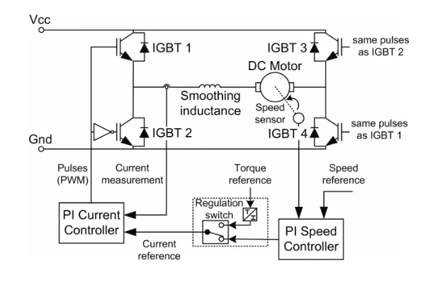
The Four-Quadrant Chopper DC Drive (DC7) block represents a four-quadrant, DC-supplied, chopper (or DC-DC PWM converter) drive for DC motors. This drive features closed-loop speed control with four-quadrant operation. The speed control loop outputs the reference armature current of the machine. Using a PI current controller, the chopper duty cycle corresponding to the commanded armature current is derived. This duty cycle is then compared with a sawtooth carrier signal to obtain the required PWM signals for the chopper.
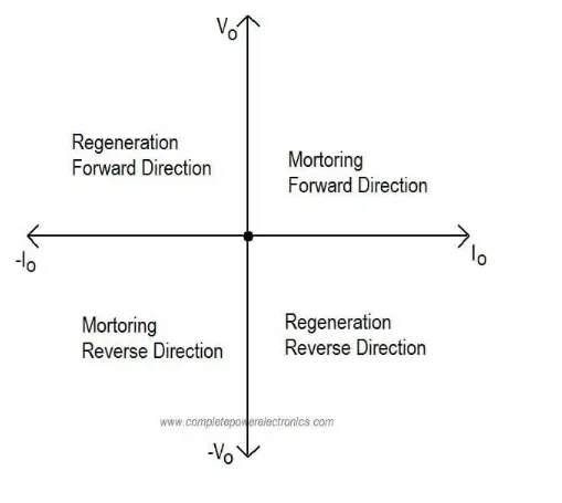
The main advantage of this drive, compared with other DC drives, is that it can operate in all four quadrants (forward motoring, reverse regeneration, reverse motoring, and forward regeneration). In addition, due to the use of high switching frequency DC-DC converters, a lower armature current ripple (compared with thyristor-based DC drives) is obtained. However, four switching devices are required, which increases the complexity of the drive system.
H bridge
An H-bridge is an electronic circuit that switches the polarity of a voltage applied to a load. These circuits are often used in robotics and other applications to allow DC motors to run forwards or backwards.
Most DC-to-AC converters , most AC/AC converters, the DC-to-DC push–pull converter, isolated DC-to-DC converter most motor controllers, and many other kinds of power electronics use H bridges. In particular, a bipolar stepper motor is almost always driven by a motor controller containing two H bridges.
‘The Four-Quadrant Chopper DC Drive (DC7) block’. Vs H-bridge model.
| H-bridge Model | DC& drive |
| Operates in forward motoring & Reverse motoring i.e; 1st and 3rd quadrant | Operates in all four quadrants forward motoring & breaking , Reverse motoring & braking. |
| Closed loop chopper feed back circuit from output to input | Open loop chopper |
| Armature current oscillations are reduced by a smoothing inductance | Need lower duty cycle for reducing armature current ripples |
| PI controller are used for dynamic control of pulse width | Fixed value of pulse width for the simulation , as there is no feedback. |
| Continous computation requires extensive computaion | Discrete computation for the model hence quick. |
3.Make a suitable EV model using DC7 block and make a result report.
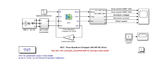
This is the model with DC7 block
Description
The 200 HP DC motor is separately excited with a constant 150 V DC field voltage source. The armature voltage is provided by an IGBT converter controlled by two PI regulators. The converter is fed by a 515 V DC bus obtained by rectification of a 380 V AC 50 Hz voltage source. In order to limit the DC bus voltage during dynamic braking mode, a braking chopper has been added between the diode rectifier and the DC7 block.
The first regulator is a speed regulator, followed by a current regulator. The speed regulator outputs the armature current reference (in p.u.) used by the current controller in order to obtain the electromagnetic torque needed to reach the desired speed. The speed reference change rate follows acceleration and deceleration ramps in order to avoid sudden reference changes that could cause armature over-current and destabilize the system. The current regulator controls the armature current by computing the appropriate duty ratios of the 5 kHz pulses of the four IGBT devices (Pulse Width Modulation). For proper system behaviour, the instantaneous pulse values of IGBT devices 1 and 4 are opposite to those of IGBT devices 2 and 3. This generates the average armature voltage needed to obtain the desired armature current. In order to limit the amplitude of the current oscillations, a smoothing inductance is placed in series with the armature circuit.
Remove the speed reference , converter and power source blocks of the original model .
To model DC7 for an electric vehicle
Connect the DC voltage source and drive cycle blocks as shown in the below.
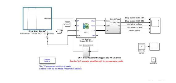
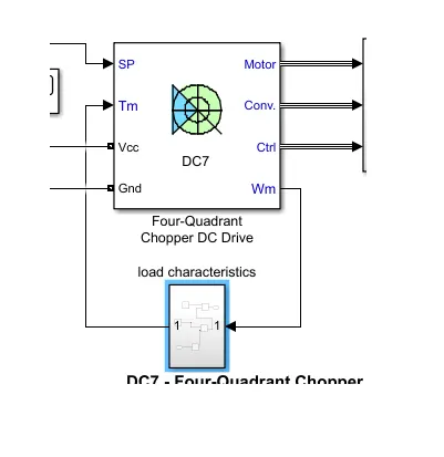
In the model replace the linear torque load block with the load characteristic subsystem.
Torque -Speed characteristics equation
`T=24.7+0.0051*omega^2`
Create a subsystem according to the characteristics equation and name as a load characteristics as shown in below
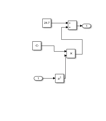
Connect the omega signal to inport and outport is connect to the torque signal. According to the fig. Below
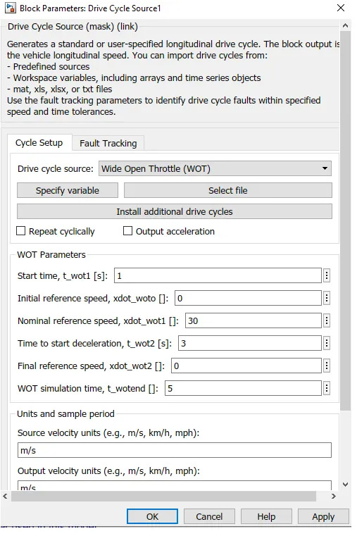
Change the type of the drive cycle source in the drive cycle block as shown in the fig.
After changing all the blocks and connections run the model .Observe the resultant graphs .
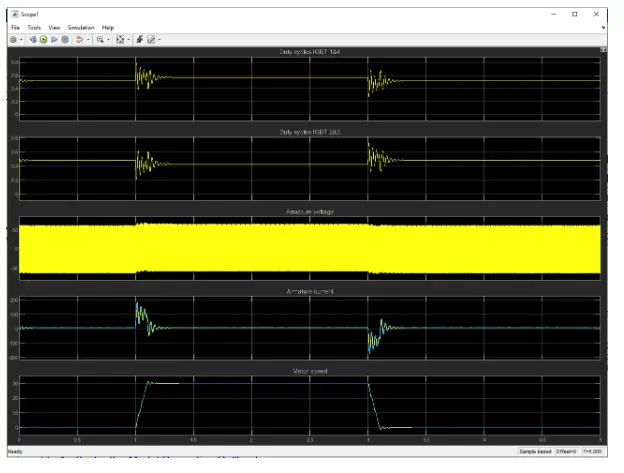
Exactly at one second acceralaration is started and at 3rd second deccelaration is occuring.According to that armature voltage current , IGBT currents are effected .
Hence the speed of the motor is changing according to the drive cycle .resultant graphs of the armature voltage and current are respectively
- Operation of BLDC motor.
BLDC motor.
A brushless DC electric motor (BLDC motor or BL motor), also known as an electronically commutated motor (ECM or EC motor) or synchronous DC motor, is a synchronous motor using a direct current (DC) electric power supply.
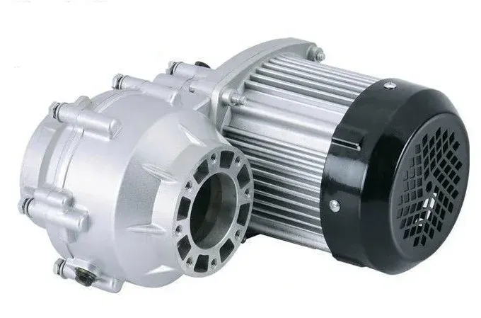
The armature coils are switched electronically by transistors at the correct rotor position in such a way that the armature field is in space quadrature with the rotor field poles. Hence the force acting on the rotor causes it to rotate. Hall sensors or rotary encoders are most commonly used to sense the position of the rotor and are positioned around the stator. The rotor position feedback from the sensor helps to determine when to switch the armature current.
This electronic commutation arrangement eliminates the commutator arrangement and brushes in a DC motor and hence more reliable and less noisy operation is achieved. Due to the absence of brushes BLDC motors are capable to run at high speeds. The efficiency of BLDC motors is typically 85 to 90 percent, whereas brushed type DC motors are 75 to 80 percent efficient. There are wide varieties of BLDC motors available ranging from small power range to fractional horsepower, integral horsepower and large power ranges.
Operation of BLDC motor
BLDC motor works on the principle similar to that of a conventional DC motor, i.e., the Lorentz force law which states that whenever a current carrying conductor is placed in a magnetic field it experiences a force. As a consequence of reaction force, the magnet will experience an equal and opposite force. In case of a BLDC motor, the current carrying conductor is stationary while the permanent magnet moves.
When the stator coils are electrically switched by a supply source, it becomes electromagnet and starts producing the uniform field in the air gap. Though the source of supply is DC, switching makes to generate an AC voltage waveform with trapezoidal shape. Due to the force of interaction between electromagnet stator and permanent magnet rotor, the rotor continues to rotate.
Consider the figure below in which the motor stator is excited based on different switching states. With the switching of windings as High and Low signals, corresponding windings are energized as North and South poles. The permanent magnet rotor with North and South poles align with stator poles causing the motor to rotate.
Observe that the motor produces torque because of the development of attraction forces (when North-South or South-North alignment) and repulsion forces (when North-North or South-South alignment). By this way the motor moves in a clockwise direction.
Here, one might get a question about how we know which stator coil should be energized and when to do. This is because; the motor continuous rotation depends on the switching sequence around the coils. As discussed above, Hall sensors give shaft position feedback to the electronic controller unit.
Based on this signal from the sensor, the controller decides particular coils to energize. Hall-effect sensors generate Low and High level signals whenever rotor poles pass near to it. These signals determine the position of the shaft.
Advantages
The advantages of a brushless motor over brushed motor are high power-to-weight ratio, high speed, nearly instantaneous control of speed (rpm) and torque, high efficiency, and low maintenance. Brushless motors find applications in such places as computer peripherals (disk drives, printers), hand-held power tools, and vehicles ranging from model aircraft to automobiles. In modern washing machines, brushless DC motors have allowed replacement of rubber belts and gearboxes by a direct-drive design.
CONCLUSION
- Run MATLAB demo ‘Speed control of a DC motor using BJT H-bridge’. Modify the model such that armature current doesn’t shoot up when motor changes direction from forward to reverse is done.
- Refer to help section of ‘The Four-Quadrant Chopper DC Drive (DC7) block’. Comparation it with H-bridge model is completed.
- Design a suitable EV model using DC7 block and make result report is finished successfully.
- Explanation about operation of BLDC motor is completed.