Week-7 Challenge: DC Motor Control
- Run MATLAB demo ‘Speed control of a DC motor using BJT H-bridge’. Modify the model such that armature current doesn’t shoot up when motor changes direction from forward to reverse.
What is BJT
A Bipolar Junction Transistor, or BJT, is a solid-state device in which the current flow between two terminals (the collector and the emitter) is controlled by the amount of current that flows through a third terminal (the base).
How does BJT works-
A BJT is a type of transistor that uses both electrons and holes as charge carriers. A signal of small amplitude if applied to the base is available in the amplified form at the collector of the transistor. This is the amplification provided by the BJT.
H-Bridge:-
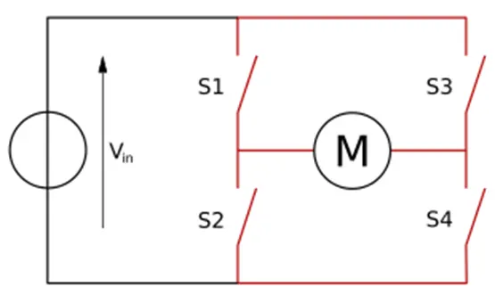
An H-bridge is an electronic circuit that switches the polarity of a voltage applied to a load. These circuits are often used in robotics and other applications to allow DC motors to run forwards or backwards.
The term H-bridge is derived from the typical graphical representation of such a circuit. An H-bridge is built with four switches (solid-state or mechanical). When the switches S1 and S4 (according to the first figure) are closed (and S2 and S3 are open) a positive voltage is applied across the motor. By opening S1 and S4 switches and closing S2 and S3 switches, this voltage is reversed, allowing reverse operation of the motor.
Using the nomenclature above, the switches S1 and S2 should never be closed at the same time, as this would cause a short circuit on the input voltage source. The same applies to the switches S3 and S4. This condition is known as shoot-through.
For running the matlab demo of ‘Speed control of a DC motor using BJT H-bridge’ open the matlab software and in Help section type the ‘Speed control of a DC motor using BJT H-bridge’ the matlab model will get open.
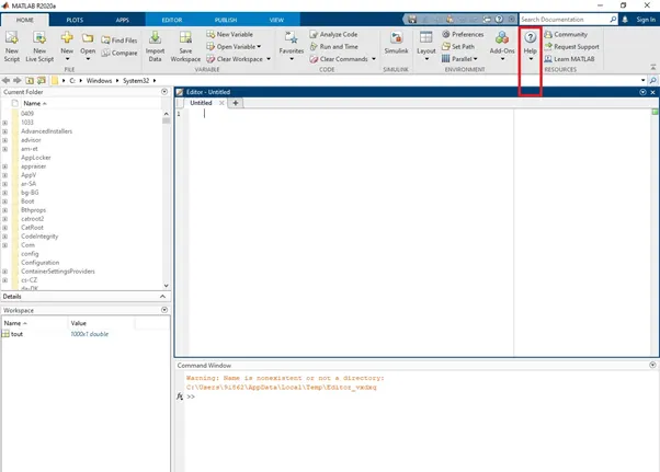
In help type the ‘Speed control of a DC motor using BJT H-bridge’ and the model information will get open , after that open that mode in matlab window.
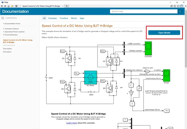
The model will look like follows after opening:-
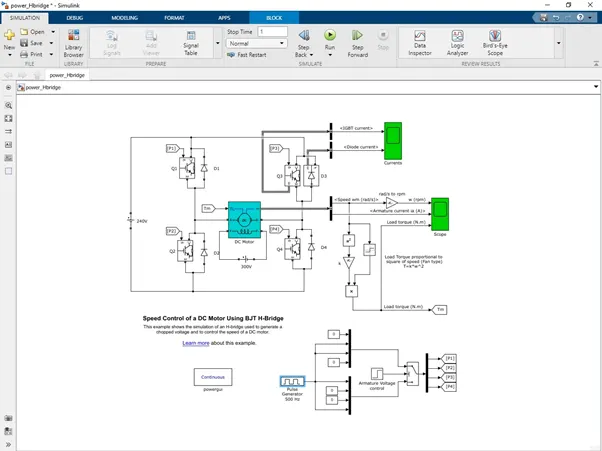
The Bipolar Junction Transistor (BJT) when used for power switching applications, operates as an IGBT. When it is conducting (BJT operating in the saturated region), a forward voltage Vf is developed between collector and emitter (in the range of 1 V). Therefore, the IGBT block can be used to model the BJT device.
The IGBT block does not simulate the gate current controlling the BJT or IGBT. The switch is controlled by a Simulink® signal (1/0). The DC motor uses the preset model (5 HP 24V 1750 rpm). It simulates a fan type load (where Load torque is proportional to square of speed). The armature mean voltage can be varied from 0 to 240 V when the duty cycle (specified in the Pulse Generator block) is varied from 0 to 100%.
The H-bridge consists of four BJT/Diode pairs (BJT simulated by IGBT models). Two transistors are switched simultaneously: Q1 and Q4 or Q2 and Q3. When Q1 and Q4 are fired, a positive voltage is applied to the motor and diodes D2-D3 operate as free-wheeling diodes when Q1 and Q4 are switched off. When Q2 and Q3 are fired, a negative voltage is applied to the motor and diodes D1-D4 operate as free-wheeling diodes when Q2 and Q3 are switched off.
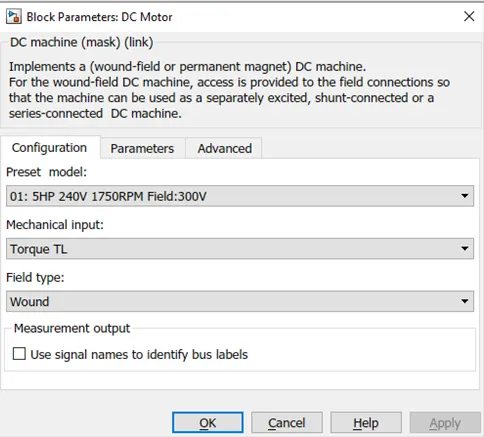
The motor block as parameters set as follows-
The motor starts in the positive direction with a duty cycle of 75% (mean DC voltage of 180V). At t= 0.5 sec., the armature voltage is suddenly reversed and the motor runs in the negative direction.
'Scope' shows motor speed, armature current and load torque and 'Currents' shows currents flowing in BJT Q3 and diode D3.
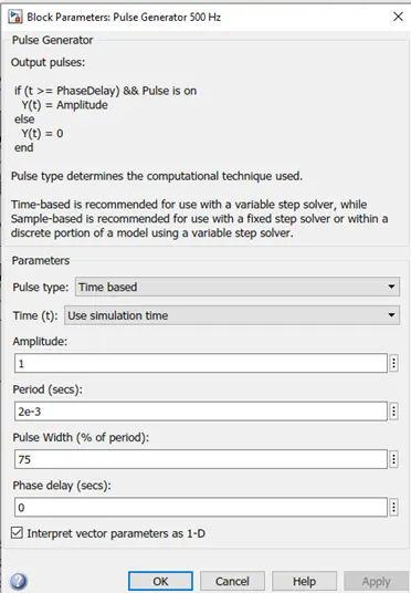
The duty cycles are set in pulse generator block with 75 % duty cycle-
When the simulation is run for the first time , without changing any parameters , keeping all parameters same the results obtained are discussed below-
The max speed which can be achieved is about 951 rpm
The maximum torque which is obtained is 6.04Nm and minimum torque is -6.04 Nm
Results :-
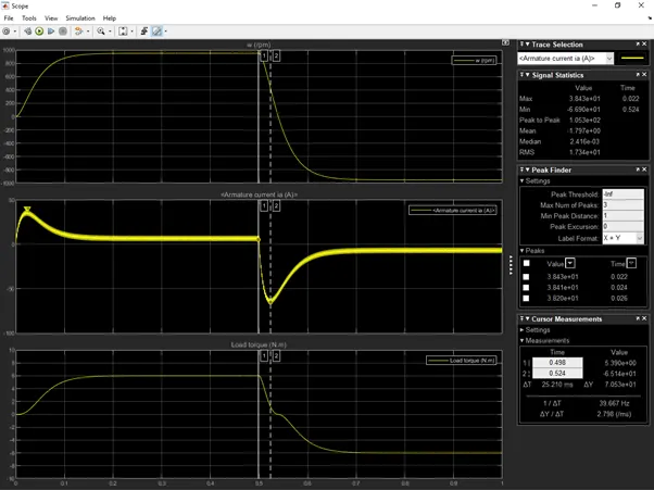
The armature current shoot up when motor changes direction from forward to reverse is about 69.90A , which is too large we have to overcome this and reduce the current shoot up we need to modify the mode , this can be done by changing the Duty cycles.
We can change the Duty cycles by opening the pulse generator block-
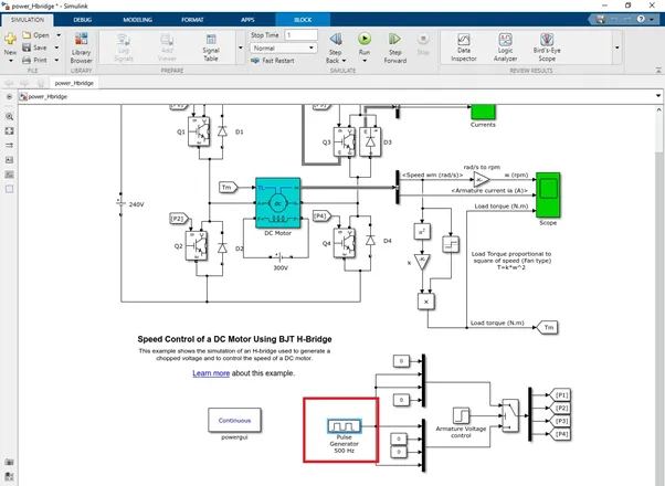
Open the pulse generator block and change the duty cycles and observe the results-
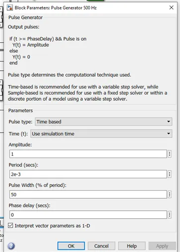
Here the duty cycle is set to 50%
The results obtained after running this simulation are as follows-
The max speed which can be achieved is about 443 rpm which is been reduced from 951 rpm
The maximum torque which is obtained is 1.3Nm and minimum torque is -1.003 Nm
The current shooting is been reduced to 17A.
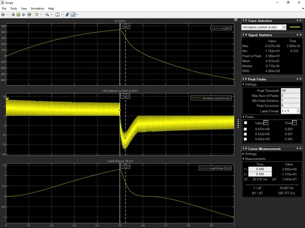
Now again the duty cycle is lowered and the results are been checked-
Here the duty cycle is set to 30%
The results obtained after running this simulation are as follows-
The max speed which can be achieved is about 165 rpm which is been reduced from 951 rpm
The maximum torque which is obtained is 0.18Nm and minimum torque is -0.009 Nm
The current shooting is been reduced to -5.42A.
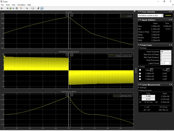
The second method by which we can reduce the current shooting of motor when changing the direction from positive to negative can be achieved by increasing the resistance of D3 diode.
Conclusion :-
For lowering the current shooting we have to decrease the duty cycles , after lowering the duty cycle percentage the current shooting is been reduced.
For lowering the current shooting we have to increase the resistance of D3 diode , after increasing the resistance the current shooting is been reduced.
2.Refer to help section of ‘The Four-Quadrant Chopper DC Drive (DC7) block’. Compare it with H-bridge model.
A four quadrant chopper is a chopper which can operated in all the four quadrants. The power can flow either from source to load or load to source in this chopper. In first quadrant, a Class-E chopper acts as a Step-down chopper whereas in second quadrant it behaves as a Step-up chopper. This type of chopper is also known as Class-E or Type-E chopper. This article describes the working principle and operation of Class-E chopper with the help of circuit diagram.
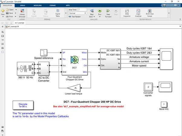
Working Principle / Operation of Class-E Chopper:
The circuit of a four quadrant chopper or class-E chopper basically consists of four semiconductor switches CH1 to CH4 and four diodes D1 to D4. The four diodes are connected in anti-parallel. The circuit diagram of this type of chopper is shown below.
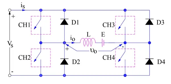
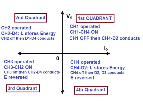
In the above circuit diagram, the choppers are numbered CH1 to CH4. For first quadrant operation CH1 is made ON, for second quadrant operation CH2 is made ON and so on.
First Quadrant Operation:
For first quadrant operation, CH4 is kept ON, CH3 is kept OFF and CH1 is operated. When both CH1 & CH4 are ON simultaneously, the load gets directly connected to the source and hence the output voltage becomes equal to the source voltage. This essentially means that vo = vs. It may be noted that the load current flows from source to load as shown by the direction of io.
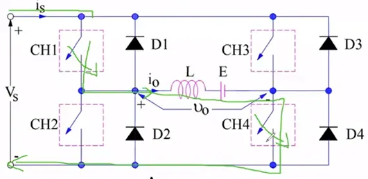
When CH1 is switched OFF, the load current free wheels through CH4 and D2. During this period, the load voltage and current remains positive.
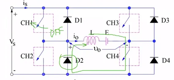
Thus, both the output voltage vs and load current io are positive and hence, the operation of chopper is in first quadrant. It may be noted that, Class-E chopper operates as a step-down chopper in this case.
Second Quadrant Operation:
To obtain second quadrant operation, CH2 is operated while keeping the CH1, CH3 & CH4 OFF. When CH2 is ON, the DC source in the load drives current through CH2, D4, E and L. Inductor L stores energy during the On period of CH2.
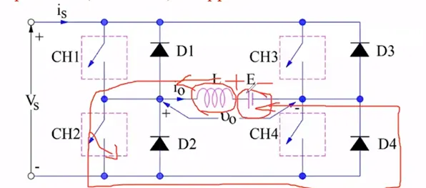
When CH2 is turned OFF, current is fed back to the source through D1, D4. It should be noted at this point that (E+Ldi/dt) is more than the source voltage Vs. As load voltage Vo is positive and Io is negative, it is second quadrant operation of chopper. Since, the current is fed back to the source, this simply means that load is transferring power to the source
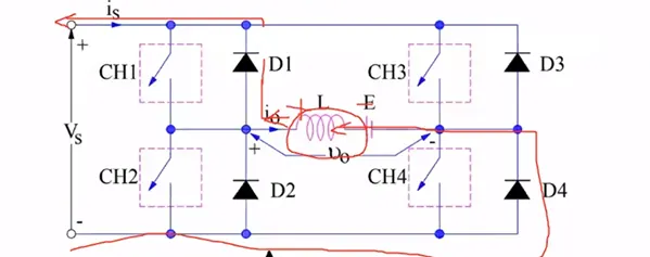
For second quadrant operation, load must contain emf E as shown in the circuit diagram. In second quadrant, configuration operates as a step-up chopper.
Third Quadrant Operation:
To obtain third quadrant operation, both the load voltage and load current should be negative.
Polarity of Load emf E reversed
For third quadrant operation, CH1 is kept off, CH2 is kept ON and CH3 is operated. When CH3 is ON, load gets connected to source and hence load voltage is equal to source voltage. But carefully observe that the polarity of load voltage vo is opposite to what shown in the circuit diagram. Hence, vo is assumed negative.
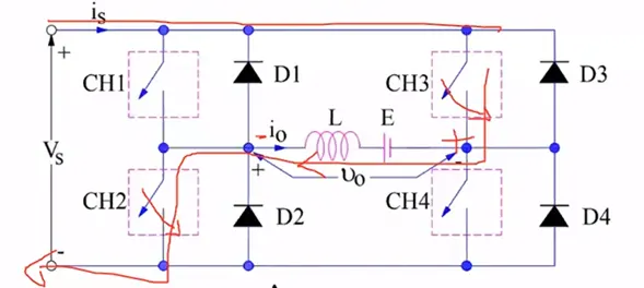
Now, when CH3 is turned OFF, the negative load current free wheels through the CH2 and D4. In this manner, vo and io both are negative. Hence, the chopper operates in third quadrant.
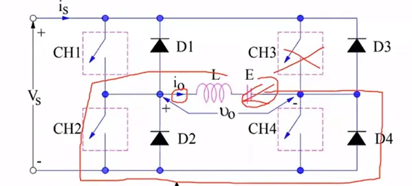
Fourth Quadrant Operation:
To obtain fourth quadrant operation, CH4 is operated while keeping CH1, CH2 and CH3 OFF. The polarity of load emf E needs to be reversed in this case too like third quadrant operati
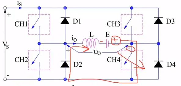
When CH4 is turned ON, positive current flows through CH4, D2, L and E. Inductance L stores energy during the time CH4 is ON. When CH4 is made OFF, current is fed back to the source through diodes D2, D3. Here load voltage is negative but the load current is always positive. This leads to chopper operation in fourth quadrant. Here, power is fed back to the source from load and chopper acts as a step-up chopper.
The operation of a four quadrant chopper or Class-E chopper :-
Difference between 4 Quadrant chopper and H-Bridge:-
|
Four Quadrant Chopper |
BJT H-Bridge |
|
it is used for industrial and commercial applications |
its commonly used for Robotics |
|
1. Forward motoring 2. Forward braking 3. Reverse motoring 4. Reverse breaking |
1. Forward motoring 2. Reverse motoring |
|
To change the rotation of motor like like forward and reverse , Signals and interrupted with one another. |
It has low switching frequency while comparing it with 4 quadrant chopper |
|
Armature current varies a little while switching from one one quadrant to another due to high switching frequency. |
The Armature current shoots up in the graph indicates the variation while switching from forward to reverse operation. |
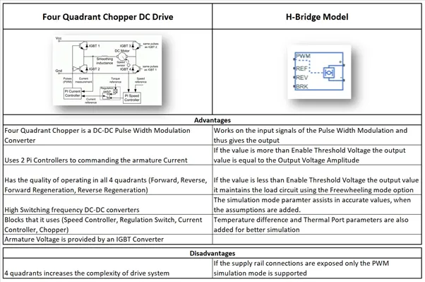
Advantages and Disadvantage of Four Quadrant and H-Bridge Model:-
3.Make a suitable EV model using DC7 block and make result report.
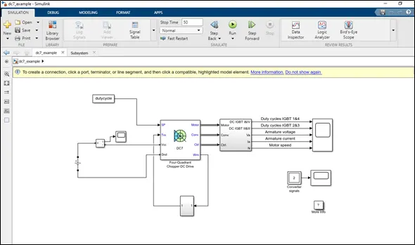
To open the DC 7 model open the help window in matlab and type the DC7 , after that the Dc7 model will appear in the window open that file in matlab.
Description of model:-
The armature voltage is provided by an IBGT converter controlled by two PI regulators. The converter is fed by by a 515 V DC bus voltage source. In order to limit thr DC bus Voltage during dynamic braking mode , a braking chopper is been added between the diode rectifier and the Dc & block.
The first regulator is a speed regulator , followed by a current regulator. The speed regulator outputs the armature current reference used by the current controller in order to obtain the electromagnetic torque needed to reach the desired speed. The speed reference changes the rate follows acceleration and deacceleration ramps in order to avoid sudden reference changes that could cause armature over-current and destabilize the system. The current regulator controls controls the armature current by computing the appropriate duty ratios of the 5khz pulses of four IGBT device 2 & 3. This generates the average armature voltage needed to obtain the desired armature current, in order to limit the amplitude of the current oscillations , a smoothing inductance is placed in series with the armature circuit.
For making a suitable change for modifying for EV , we have to make some changes in the power supply ,
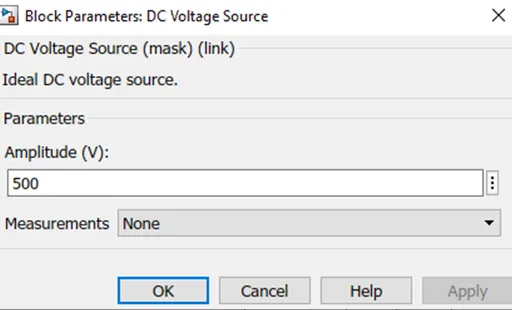
A Dc voltage source is been taken as a power supply source and the voltage is been set as 500 V Dc .
Set parameter for dc voltage source:-
The next step is to create the driving cycle as per are requirement and import it in the matlab.

The driving cycle is been created in excel sheet and imported in matlab
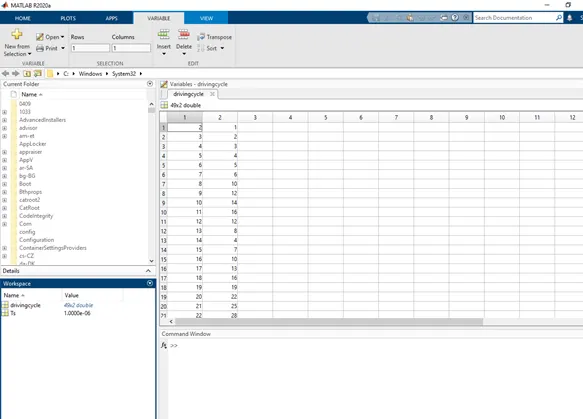
Use from workspace block in Simulink to add this driving cycle to theDC7 model
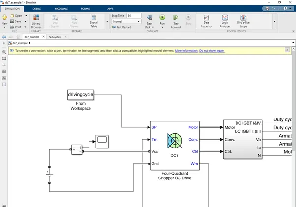
The next step is to create the Vehicle Load Characteristics :-
Linear torque block is been replaced with a subsystem model according to load characteristics given
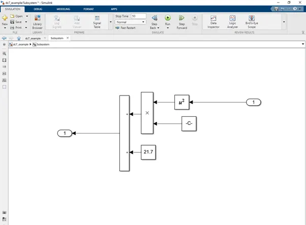
Equation :-
`T=24.7+0.0051w^2`
Results :-
The simulation is been carried for 50 sec the results obtained are as follows :-
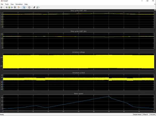
In this scope the Duty cycles of IGBT 1&4 , duty cycle of IGBT 2&3 , armature voltage , armature current and motor speed (driving cycle data) are been plotted.
4.Explain in a brief about operation of BLDC motor.
A brushless DC motor (also known as a BLDC motor or BL motor) is an electronically commuted DC motor which does not have brushes. The controller provides pulses of current to the motor windings which control the speed and torque of the synchronous motor.
These types of motors are highly efficient in producing a large amount of torque over a vast speed range. In brushless motors, permanent magnets rotate around a fixed armature and overcome the problem of connecting current to the armature. Commutation with electronics has a large scope of capabilities and flexibility. They are known for smooth operation and holding torque when stationary.
How Does a Brushless Motor Work
Before explaining the working of a brushless DC motor, it is better to understand the function of a brushed motor. In brushes motors, there are permanent magnets on the outside and a spinning armature which contains electromagnet is inside. These electromagnets create a magnetic field in the armature when the power is switched on and help to rotate the armature.
The brushes change the polarity of the pole to keep the rotation on of the armature. The basic working principle for the brushed DC motor and for brushless DC motor are same i.e. internal shaft position feedback.
Brushless DC motor has only two basic parts: rotor and the stator. The rotor is the rotating part and has rotor magnets whereas stator is the stationary part and contains stator windings. In BLDC permanent magnets are attached in the rotor and move the electromagnets to the stator. The high power transistors are used to activate electromagnets for the shaft turns. The controller performs power distribution by using a solid-state circuit.
Construction of Brushless DC motor
In this motor, the permanent magnets attach to the rotor. The current-carrying conductors or armature windings are located on the stator. They use electrical commutation to convert electrical energy into mechanical energy.
The main design difference between a brushed and brushless motors is the replacement of mechanical commutator with an electric switch circuit. A BLDC Motor is a type of synchronous motor in the sense that the magnetic field generated by the stator and the rotor revolve at the same frequency.
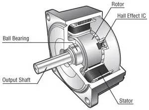
Brushless motor does not have any current carrying commutators. The field inside a brushless motor is switched through an amplifier which is triggered by the commutating device like an optical encoder.
The layout of a DC brushless motor can vary depending on whether it is in “Out runner” style or “Inrunner” style.
Working Principle of Brushless DC motor
BLDC motor works on the principle similar to that of a Brushed DC motor. The Lorentz force law which states that whenever a current carrying conductor placed in a magnetic field it experiences a force. As a consequence of reaction force, the magnet will experience an equal and opposite force. In the BLDC motor, the current carrying conductor is stationary and the permanent m
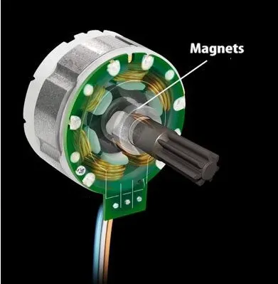
When the stator coils get a supply from source, it becomes electromagnet and starts producing the uniform field in the air gap. Though the source of supply is DC, switching makes to generate an AC voltage waveform with trapezoidal shape. Due to the force of interaction between electromagnet stator and permanent magnet rotor, the rotor continues to rotate.
With the switching of windings as High and Low signals, corresponding winding energized as North and South poles. The permanent magnet rotor with North and South poles align with stator poles which causes the motor to rotate.
Types of Brushless DC Motors
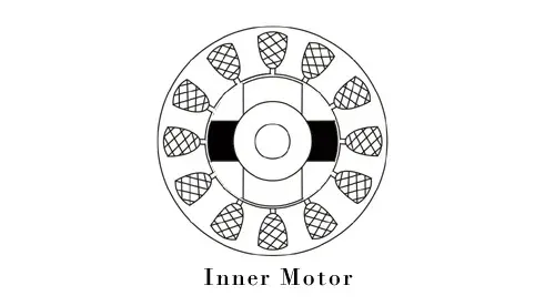
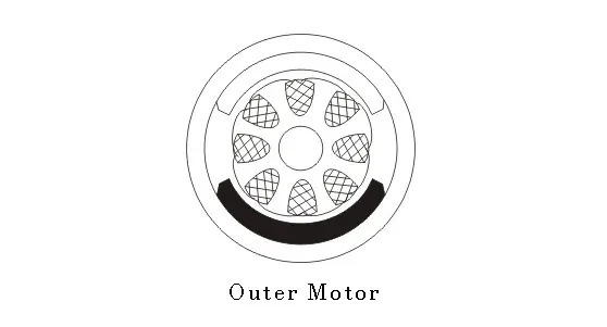
Basically, BLDC are of two types, one is outer rotor motor and other is inner rotor motor. The basic difference between the two is only in designing, their working principles are same.
Inner Rotor Design
In an inner rotor design, the rotor is located in the centre of the motor and the stator winding surround the rotor. As the rotor is located in the core, rotor magnets do not insulate heat inside and heat get dissipated easily. Due to this reason, inner rotor designed motor produces a large amount of torque and validly used.
Outer Rotor Design
In outer rotor design, the rotor surrounds the winding which is located in the core of the motor. The magnets in the rotor trap the heat of the motor inside and do not allow to dissipate from the motor. Such type of designed motor operates at lower rated current and has low cogging torque.
Advantages of Brushless DC Motor
The advantages of a BLDC motor are:
- Brushless motors are more efficient as its velocity is determined by the frequency at which current is supplied, not the voltage.
- As brushes are absent, the mechanical energy loss due to friction is less which enhanced efficiency.
- BLDC motor can operate at high-speed under any condition.
- There is no sparking and much less noise during operation.
- More electromagnets could be used on the stator for more precise control.
- BLDC motors accelerate and decelerate easily as they are having low rotor inertia.
- It is high performance motor that provides large torque per cubic inch over a vast sped rang.
- BLDC motors do not have brushes which make it more reliable, high life expectancies, and maintenance free operation.
- There is no ionizing sparks from the commutator, and electromagnetic interference is also get reduced.
- Such motors cooled by conduction and no air flow are required for inside cooling.
Disadvantages of Brushless DC Motors
The disadvantages of a BLDC motor are:
- BLDC motor cost more than a brushed DC motor.
- The limited high power could be supplied to BLDC motor, otherwise, too much heat weakens the magnets and the insulation of winding may get damaged.
Note:- The files are been attached below pls check it.