Week-7 Challenge: DC Motor Control
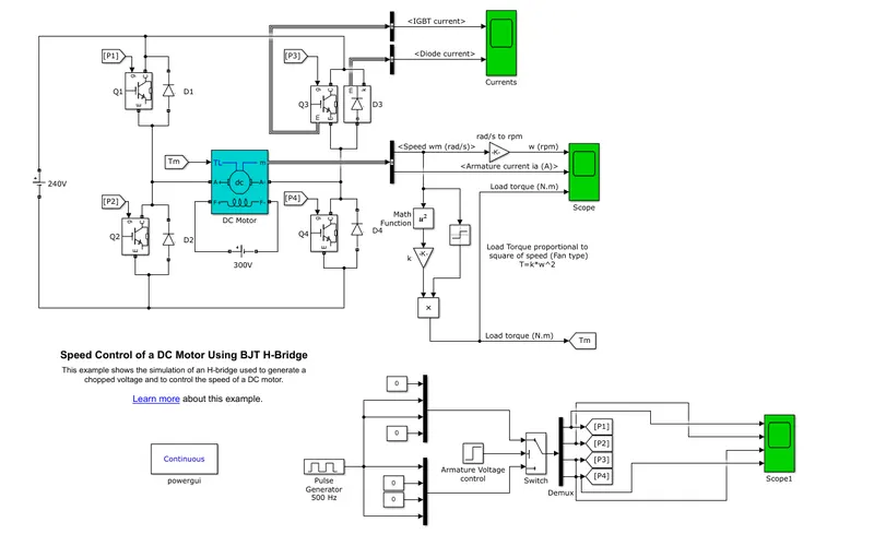
1. Problem Statement:- Run MATLAB demo ‘Speed control of a DC motor using BJT H-bridge’. Modify the model such that armature current doesn’t shoot up when motor changes direction from forward to reverse.
Solution:- In this situation IBJT is used as a switching devices to control the functioning of DC motor by regulating the armature current. We will be discussing the given model here in quite detail.
BJT, Bipolar Junction Transistor, is a type of transistor which uses holes and electrons both as a charge carrier. When it is used in switching applications ,then it is called as Insulated Gate Bipolar Transistor(IGBT). In BJT the voltage is appied between collector and emitter. The Base is feeded with a contrl voltage. When the collector and emitter terminals are forward biased the transister acts as a transistor.
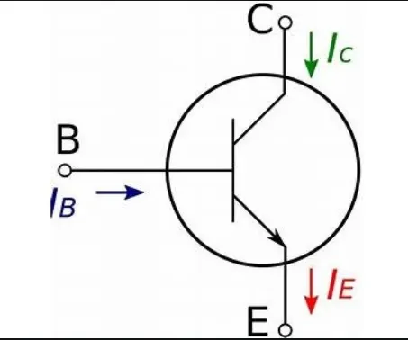
IGBT is a most commonly used poer switch in comparison to MOSFET and thyristors due to high switching frequencies.
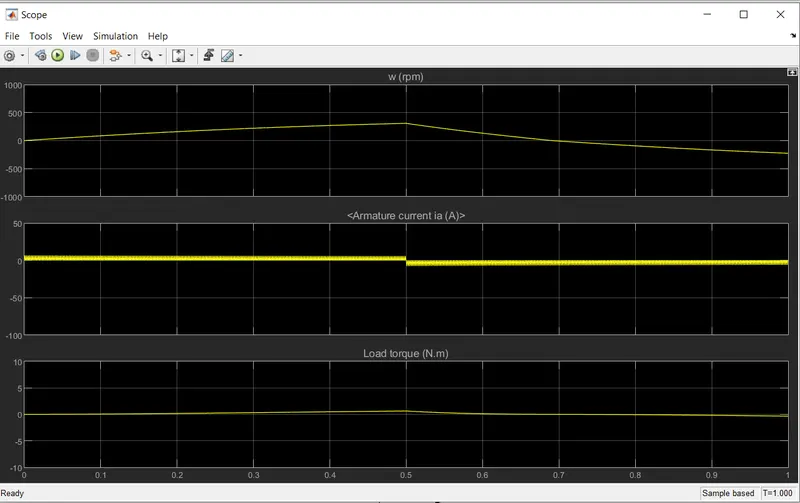
In our model a voltage of 240 v is applied between collector emitter terminals. The model has a predefined duty cycle of 75% which gives us the following output results.
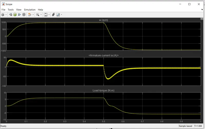
Here we can observe that the armature currents overshoots to a high value when the direction of current is changng or in other words when motor is going to reverse motoring from forward motoring. The reason behind this phenemenon can be understood as the high armature voltage. to regualte this we will have to manipulate the duty cycle to a optimum value.
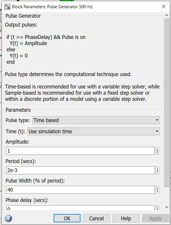
For this operation we will change the duty cycle in the pulse generator block to 40 %.
Now we can observe that our simulation results have optimised manifolds. With the effect of change in duty cycle the motor
rpm and load torque have been reduced.
2. Problem Statement:- Refer to help section of ‘The Four-Quadrant Chopper DC Drive (DC7) block’. Compare it with H-bridge model.
Solution:- With reference to the electric and hybrid electric cars there are total four motoring conditions.
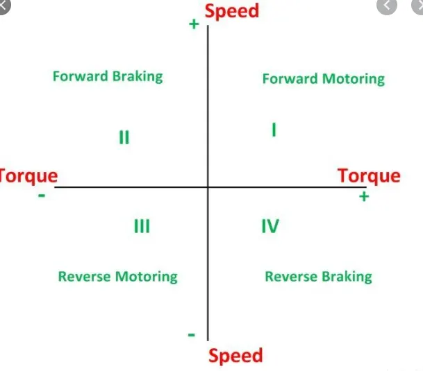
1. Forward Motoring- vehicle is moving forward and the motor is applying positive torque or in forward direction.
2. Forward Braking- vehicle is moving backward or reverse and the motor is applying positive torque or in forward direction .
3. Reverse Motoring:- vehicle is moving backward and the motor is applying negative torque or in backward direction.
4. Reverse Braking:- vehicle is moving forward and the motor is applying negative torque or in backward direction.
As we have observed in H bridge segup of IGBT there can only be two states either reverse motoring or forward motoring.
But in DC7 control drive the motor can be functioning in all four modes.
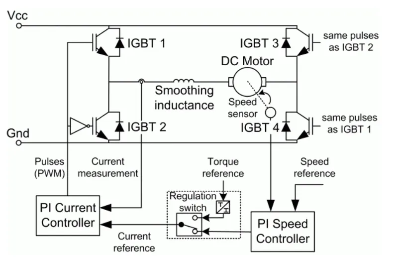
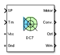
Due to availabilty of two motoring conditions in IGBT H bridge set up , they can not also be implemented in accordance with regenerative braking.
3. Problem Statement:- Make a suitable EV model using DC7 block and make result report.
Solution:- We have designed a simple EV model in which the DC7 four quadrant drive is used to regulate motor controls.
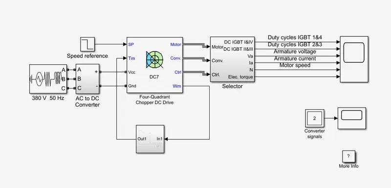
(a) Power source:- A constant voltage AC supply of 380 V at 50 hz is used to power our model.
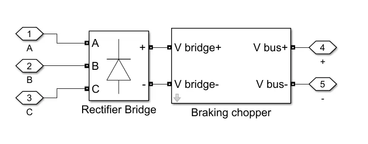
(b) AC-DC Converter:-
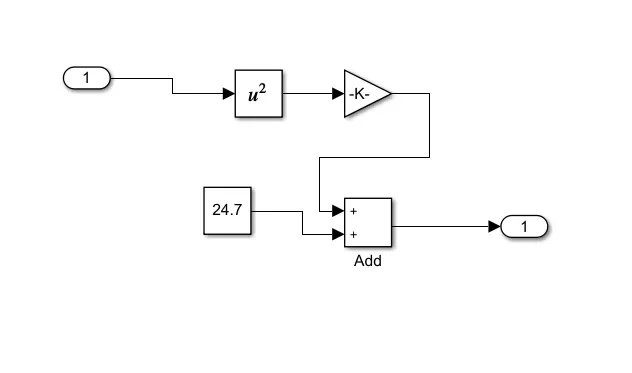
(c) Load torque :- we have use the following equation to derive our load torque from the angular speed:-
`Tm=24.7+0.0051*w^2`
the algorithm is stored in the subset as shown below:-
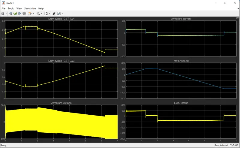
(d) results:-
4. Problem Statement:- Explain in brief about BLDC motors.
Solution:- BLDC stands for BrushLess- DC. IN conventional DC motors the brushess are one of the major sources of losses which reduces thir efficiency. In this suprficial BLDC motors the brushes have been moved out. We are going to briefly discuss the working of it.
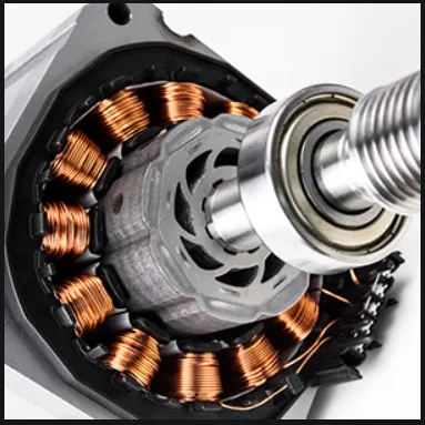
As all motors it has two main parts stator and rotors. stator has a three phase windings and rotor is attached with set of permanent magnets.
The current is passed in the stator windings such that it produces a magnetic field which interferes with permanent magnet attached to rotors which it turns provide torque to move it.
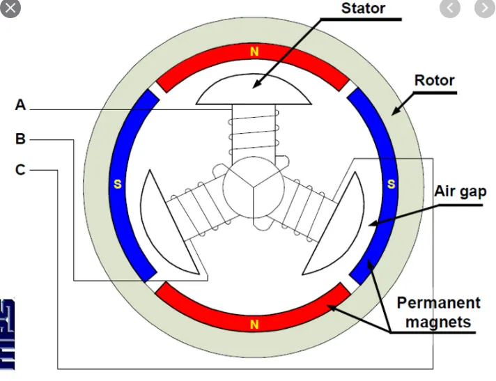
With reference to the above figure, first the current is supplied to winding A then due to magnetic field created it moves rotor next the current is supplied to winding B and A has no currents which again move the rotor and same is proceeded to C winding. This process continues in a cycle and thus produces a motoring effects.
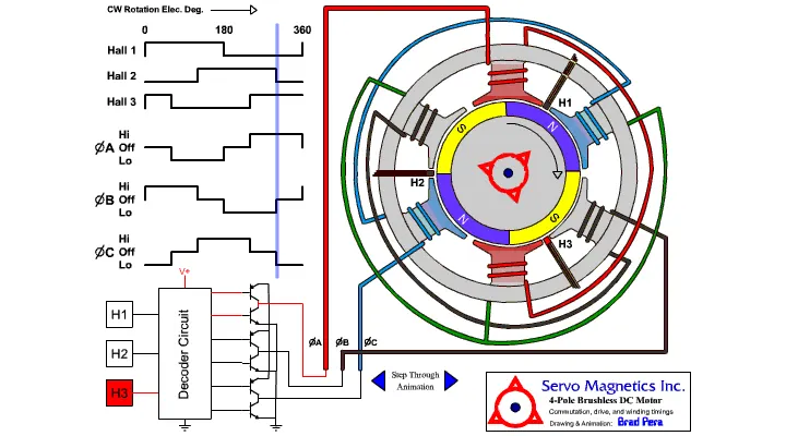
Hall sensors are placed in the motors to detect the magnetic field. This whole mechanism can be understood by a simple animation given below.
Advantages:-
1. Brushless DC motors have better performance and efficiency with respect to the brushed DC motors due to the use of electronic control enabling high-level control over the speed and position of the motor. BLDC motor lifespan is approx. 5-6 times higher than the counter brushed DC motor.
2. Brushless DC motors can provide maximum torque continuously during rotation, while brushed DC motor can provide maximum torque at an only specific point of the rotation. For the same torque rating, the brushed motor will require a much bigger magnet as compared to the brushless DC motor. This results in a very compact and small-sized brushless DC motor proving very high torque rating.
Disadvantages:-
1. The cost of a BLDC motor is higher as compared to brushed DC motor and the electronic controller also increases the cost of overall model, as in a traditional motor, low-cost mechanical commutation setup involving brushes is used.
2. When brushless DC motor is used at low speed, small vibrations occur during low-speed rotation. However, vibrations are reduced at high speed.
References:-
1. https://electricityshock.com/advantages-and-disadvantages-of-brushless-dc-motor/
2. https://www.pantechsolutions.net/blog/bldc-motor-control/