Week-7 Challenge: DC Motor Control
AIM:
- Run MATLAB demo ‘Speed control of a DC motor using BJT H-bridge’. Modify the model such that armature current doesn’t shoot up when motor changes direction from forward to reverse.
- Refer to help section of ‘The Four-Quadrant Chopper DC Drive (DC7) block’. Compare it with H-bridge model.
- Make a suitable EV model using DC7 block and make result report.
- Explain in a brief about operation of BLDC motor.
- Run MATLAB demo ‘Speed control of a DC motor using BJT H-bridge’. Modify the model such that armature current doesn’t shoot up when motor changes direction from forward to reverse.
BJT
BJT also known as bipolar junction transistor is a three – terminal semiconductor device that consists of two p-n junction that amplifies or magnifies a signal. It is a current controlled device. The three terminals of BJT are base, collector and emitter. BJT is a type of transistor that uses both electrons and holes as charge carriers.
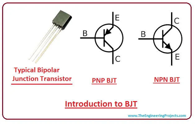
The two types of BJT are NPN and PNP transistors. The NPN transistor is made by placing the p-type material between two n-type materials and the PNP is made by placing an n type material between two p- type materials.
MOSFET
MOSFET also known as metal oxide semiconductor field effect transistor is a semiconductor device that is used for switching purposes and also amplifies electronic signals in electronic devices.
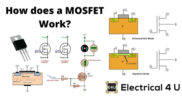
MOSFET is a four terminal device which has source (s), gate (G), drain (d) and body (b) terminals. The body of the MOSFET is connected with the terminals that forms a three terminal device such as a field –effect transistor. MOSFET is generally considered as a transistor and used in both analog and digital circuits.
IGBT
IGBT also known as insulated gate bipolar transistor is a three terminal semiconductor switching device which is used for fast switching with high efficiency in many electronic devices. These devices are mostly used in amplifiers for processing complex wave patterns with pulse width modulation.
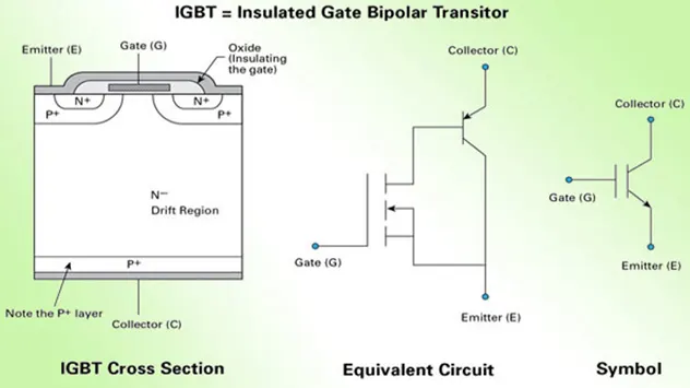
IGBT is a combination of BJT and MOSFET. The input side represents MOSFET with a gate terminal and the output side represents BJT with collector and emitter. The conduction terminals are collector and emitter and gate is the control terminal in which the switching operation is controlled.
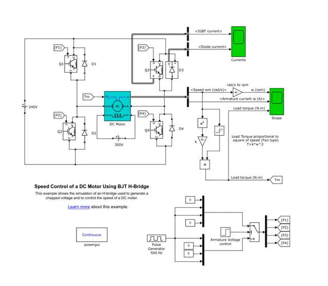
The following model of BJTH-Bridge consists of blocks like pulse generator, D.C motor, armature voltage control, IGBT, transistors, diodes, scope for plotted results and gain blocks to calculate the torque of the motor. This model depicts the output of the armature current, load torque, speed and also the currents of IGBT and diode. This model rotates in the forward direction and then in the reverse direction. So in order to decrease the sudden rise in the armature current we need to reduce the pulse width in the pulse generator block.
MODEL DESCRIPTION
The bipolar junction transistor operates as an IGBT when it used for power switching application. When it operates in the saturated region a forward voltage Vf is developed between collector and emitter in the range of 1V. So IGBT block is used to model BJT device.
The gate current controlling the BJT is not simulated by the IGBT block. The switch is controlled by a Simulink signal 1 or 0. The D.C motor uses model of 5HP 24V 1750rpm. It simulates a fan type load. The armature mean voltage varies from 0 to 240V and the duty cycle can also be varied from 0 to 100%.
The H- Bridge consists of 4 BJT. The two transistors are switched simultaneously. Q1 and Q4 or Q2 and Q3. When Q1 and Q4 are fired, a positive voltage is applied to the motor and diodes D2-D3 operate as free – wheeling diodes when Q1 and Q4 are switched off. When Q2 and Q3 are fired a negative voltage is applied to the motor and diodes D1-D4 operate as freewheeling diodes when Q2 and Q3 are switched off.
SIMULATION
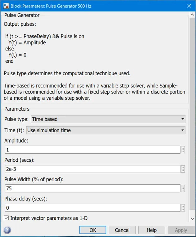
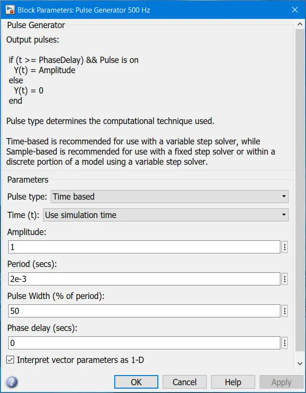
The pulse generator is used to generate pulses that are fed to four IGBTS to create pulse width modulation. In this model the motor starts in the positive direction with a duty cycle of 75% meaning D.C voltage of 180V.
Initial block parameters for pulse generator block are shown below:
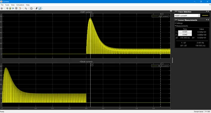
Once the simulation is run we get the following graphs which represents the motor speed, armature current, load torque and currents flowing in BJT Q3 and diode D3.
RESULTS:
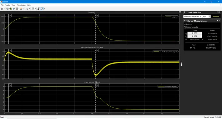
It can be observed from the above graph that at t=0.5 seconds the armature voltage is suddenly reversed and motor runs in the negative direction. During the first half of the cycle the motor acquires a speed of 1000 rpm and a load torque of 6 Nm whereas the second half of the cycle the motor runs in the negative direction. It can also be seen that the armature current of the D.C motor suddenly increases in order to reduce the armature current the pulse width is reduced in the pulse generator block.
MODIFICATION:
Modifying the model by reducing the pulse width to 50%.
When the model is simulated after the modification the following graphs are obtained
RESULTS:
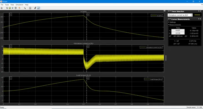
From the above graph it is observed that the armature current of D.C motor is almost 0A, which means that the armature current does not increase suddenly at 50% pulse width. Due to reduction in pulse width the motor speed and the torque is reduced to 440 rpm and 1.26 Nm respectively. This indicates that reduction in pulse width results in torque and motor speed reduction.
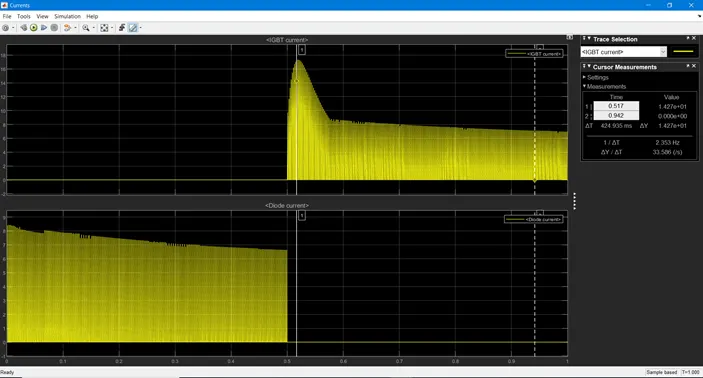
CONCLUSIONS:
- It is observed that with the reduction in pulse width in the pulse generator block does not allow the armature current to shoot up when the motor changes direction from forward to reverse.
- Refer to help section of ‘The Four-Quadrant Chopper DC Drive (DC7) block’. Compare it with H-bridge model.
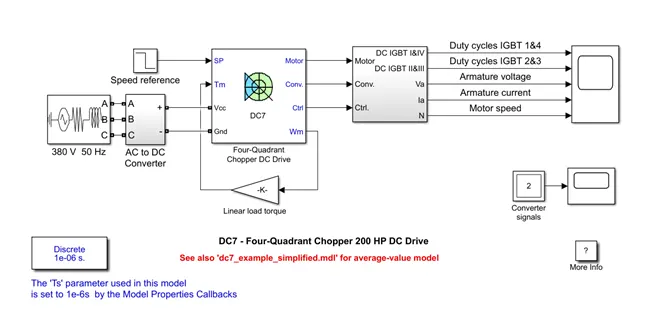
RESULTS
MODEL DESCRIPTION
The above model consists of a three phase source AC-DC converter that includes a rectifier and a four quadrant chopper D.C drive and a selector. The 200 HP DC motor is excited by 150V D.C field voltage source. The armature voltage is controlled by two PI regulators. The converter is fed by 515V DC bus obtained by the rectification of a 380V AC 50Hz voltage source. Braking chopper is added between the diode rectifier and the DC7 block in order to limit the d.c bus voltage during dynamic braking.
The first regulator is the speed regulator which is followed by a current regulator. The speed regulator that outputs the armature current reference which is used by current controller so as to obtain the electromagnetic torque which is needed to reach the desired speed. The speed reference changes rate that follows acceleration and deceleration ramps so as to avoid sudden reference changes that can cause armature over current and destabilize the system. The current regulators which controls the armature current that computes the appropriate duty ratios of 5 KHz pulses of the four IGBT devices.
For behaviour of proper system, the instantaneous pulse values of IBGT devices 1 and 4 are apposite to those of IGBT devices 2 and 3. This generates average armature voltage needed to obtain desired armature current. A smooth inductance is placed in series with armature circuit so as to limit the amplitude of current oscillations.
FOUR QUADRANT OPERATION OF D.C MOTOR
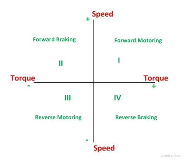
Four quadrant operation of D.C motor means that the machine operates in four quadrants that are :
- Forward braking
- Forward motoring
- Reverse motoring
- Reverse braking
A motor that operates in two modes that are motor and braking. A motor that is capable of operating in both direction of rotation and producing both motoring and regeneration is called four quadrant variable speed drive.
In motoring mode, the machine works as a motor and converts electrical energy into mechanical energy. In braking mode the motor acts as a generator and converts mechanical energy into electrical energy, it opposes the motion. So the motor can operate in both forward and reverse direction which is motoring and braking operation.
When the motor is operated in the forward direction the speed of the motor is considered positive. The rotation of the motor in the opposite direction gives reverse speed which is denoted by a negative sign.
The rate of change of speed with respect to time in the forward direction provides acceleration which is known as positive motor torque. In case of retardation the torque developed by the motor is negative.
- QUADRANT 1
In the first quadrant the power developed by the motor is positive and supplying mechanical energy so the first quadrant operation is known as forward motoring.
- QUADRANT 2
In this quadrant the operation performed is known as braking. In this quadrant the power developed by the motor is negative as the direction of rotation is positive and the torque is negative so the motor act as a generator that opposes the motion.
- QUADRANT 3
The third quadrant is known as reverse motoring so in this motor works in the reverse direction where both speed and torque have negative values which makes the power positive.
- QUADRANT 4
The torque developed by the motor is positive and the speed is negative so this quadrant refers to braking in the reverse motoring mode.
|
Function |
Quadrant |
Speed |
Torque |
Power output |
|
Forward motoring |
1 |
+ |
+ |
+ |
|
Forward braking |
2 |
+ |
- |
- |
|
Reverse motoring |
3 |
- |
- |
+ |
|
Reverse braking |
4 |
- |
+ |
- |
COMPARISON BETWEEN FOUR QUADRANT CHOPPER D.C DRIVE MODEL AND H- BRIDGE MODEL
|
s.no |
FOUR QUADRANT CHOPPER D.C DRIVE MODEL |
H-BRIDGE MODEL |
|
1. |
It operates in 4- quadrants : 1. Forward motoring 2. Forward breaking 3. Reverse motoring 4. Reverse breaking |
It operates in 2 quadrants 1. Forward motoring 2. Reverse motoring |
|
2. |
Two PI regulators ( speed regulator and current regulator) are used to obtain electromagnetic torque so that the desired speed is achieved |
No PI regulators are used |
|
3. |
Four Quadrant switch is an electronic switch that interrupts one signal under the control of another. |
H- bridge model is an electronic switch that switches the polarity of voltage |
|
4. |
Better efficiency and high power storage than H- bridge model. |
Less efficiency and power storage as compared to four-quadrant chopper. |
|
5. |
Used in Robotics and other applications that allow D.C motor to run in forward and reverse direction. |
Used mainly in power control and signal application. |
|
6. |
Regenerative braking is possible |
Regenerative braking is not possible. |
CONCLUSION
Four quadrant chopper when compared with H- bridge model it was found that the four quadrant chopper had higher efficiency and power storage.
- Make a suitable EV model using DC7 block and make result report.
An electric vehicle uses a D.C motor which needs to perform all four operation of forward and reverse motoring and braking.
The D.C 7 model is modified so as to analyse the results for an electric vehicle
The modifications are:
- DRIVE CYCLE
- LINEAR TORQUE LOAD
- POWER SOURCE
- DRIVE CYCLE
In the DC7 block initially there was a speed reference block which gives the motor speed requirement in rpm . For modelling the electric vehicle a drive cycle is created with our own values of speed with respect to time.
The drive cycle created for DC 7 - FOUR QUADRANT D.C CHOPPER DRIVE model is shown below where there is variation in speed with respect to time.
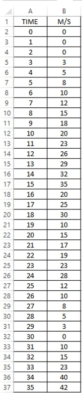
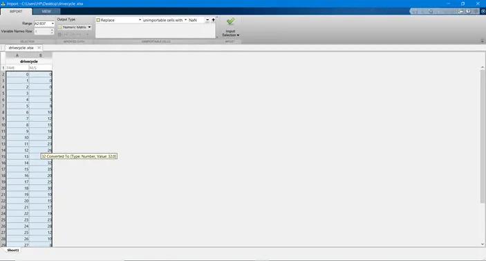
The values of both time and velocity were exported into matlab workspace converting them into numeric matrix from the ‘OUTPUT TYPE SELCTION ’as shown below:
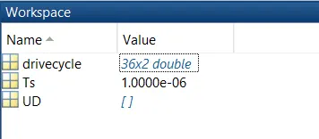
Workspace after the excel sheet is imported
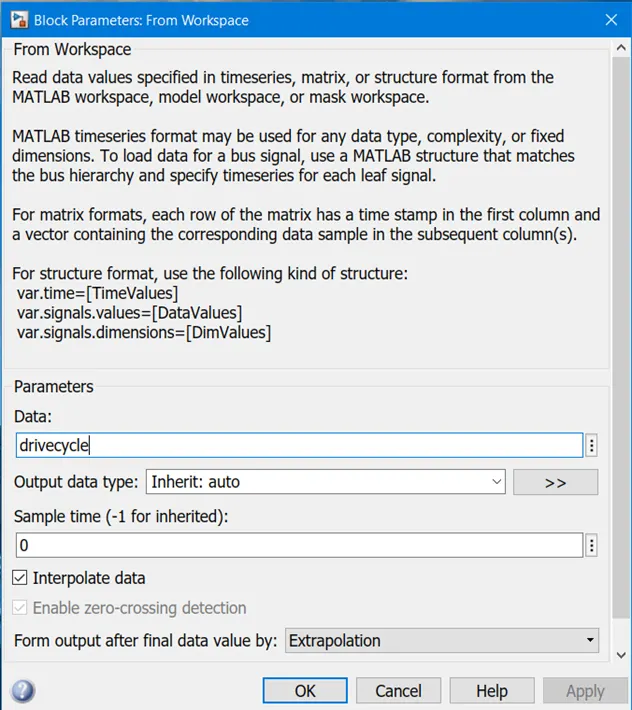
The values were then inserted into the Simulink model using the block ‘FROM WORKSPACE’ block of the Simulink.
- LINEAR LOAD TORQUE
For modelling the electric vehicle we consider the load characteristics of the vehicle taking into account of all the external forces like resistance force and air drag.
The below equation is inserted in the model using a subsystem that takes ω as input from the DC 7 block and calculates the load characteristics equation as shown below :
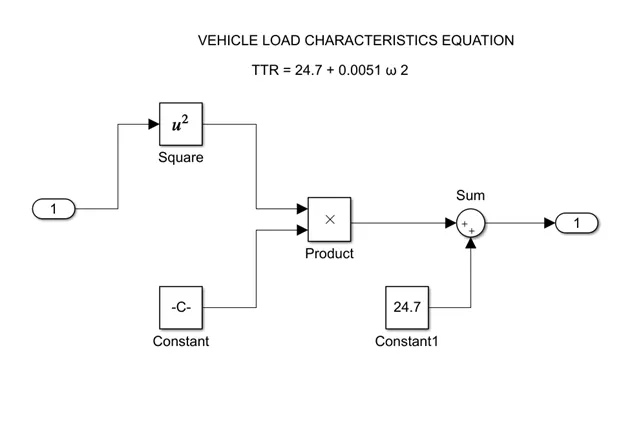
The linear load block is replaced with the above subsystem and is connected back to the torque in the DC 7 block.
- POWER SOURCE
A.C power source is replaced with a D.C voltage source with a voltage similar to that of a real car battery.
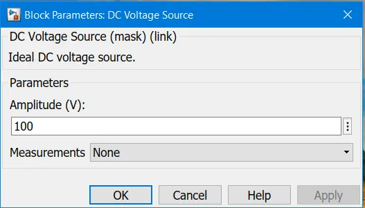
D.C VOLTAGE SOURCE
This block represents an ideal D.C voltage source. This voltage can be changed any time during the simulation.
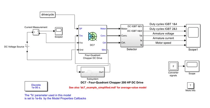
The Simulink model for the DC7- FOUR QUADRANT CHOPPER D.C DRIVE is shown below:
The following blocks that were used in the model:
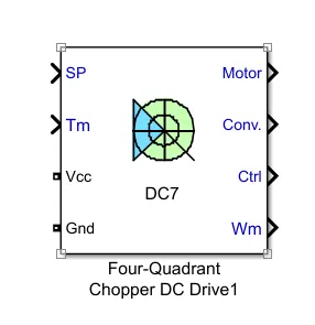
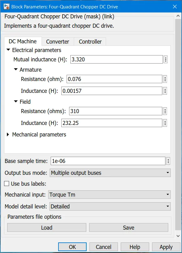
- FOUR- QUADRANT CHOPPER D.C DRIVE
The four quadrant chopper D.C drive represents a four quadrant, chopper drive for D.C motors. This drive features closed – loop speed control with four quadrant operation. Main advantage of this drive than other D.C drives is that it operates in all four quadrants forward motoring , reverse regeneration , reverse motoring and forward regeneration.
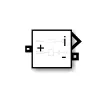
- CURRENT MEASUREMENT
This block measures the current flowing in the electrical block
EXPLANATION
- In the above model for creating an electric vehicle model a FOUR QUADRANT CHOPPER D.C DRIVE is used.
- A current measurement sensor is used which is attached to scope so as to observe its nature positive terminal of the current measurement sensor is connected to the positive of the D.C voltage source and negative is connected to the Vcc of the four- quadrant chopper D.C drive.
- C voltage source is used where the positive terminal is connected to the positive of the current measurement sensor and the negative is connected to the ground of the four quadrant D.C chopper.
- The reference for speed is given as input to the chopper block which is the drive cycle
- The subsystem is created which is connected to the Wm and Tm of the four – quadrant chopper d.c drive so as to form the vehicle load characteristic equation.
- The chopper block is then connected to the IGBT transistor
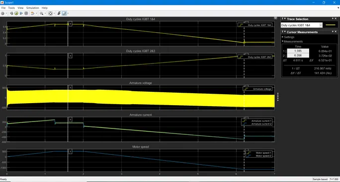
- The IGBT is then connected to the scope so as to obtain the graphs of armature voltage, armature current, motor speed and duty cycles of IGBT 1and 4, 2 and 3.
The following blocks that were used for the formation of a subsystem so as to create the vehicle load characteristics equation:
TTR = 24.7 + 0.0051 ω2
- MATHEMATICAL FUNCTION BLOCK
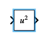
It is a mathematical function block that performs mathematical functions which includes exponential power and modulus function.
- CONSTANT BLOCK
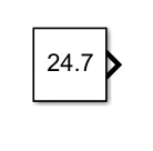
This block is represented by the constant value parameter
- PRODUCT BLOCK
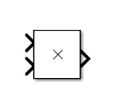
This product block gives the output by multiplying the inputs
- ADDITION BLOCK
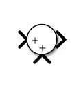
This block performs addition or subtraction of its inputs
RESULTS:
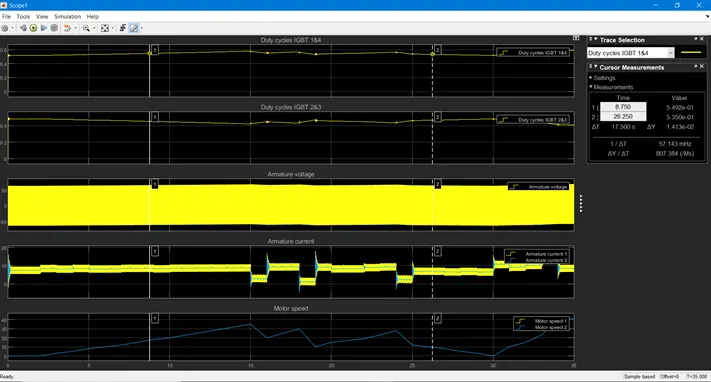
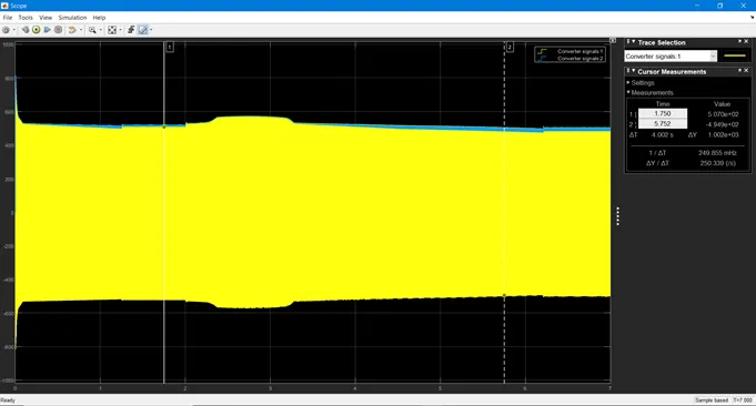
The current, motor voltage the four IGBT pulses and motor rpm was observed on the scope.
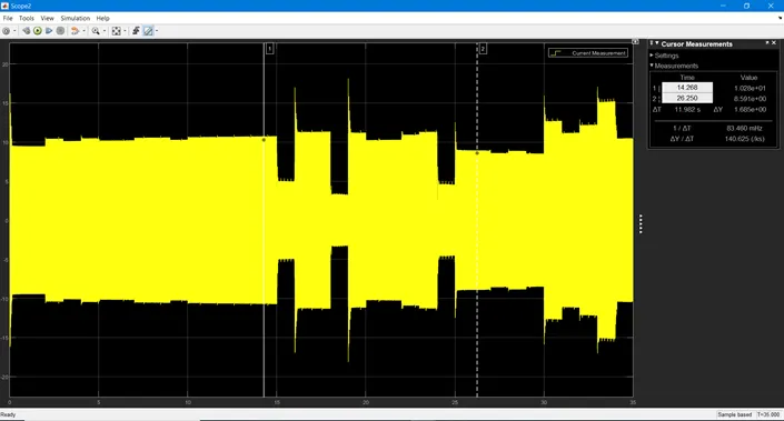
At t = 15 seconds the current is reversed to produce regenerative braking which causes the battery voltage to increase.
Current measurement sensor is used to measure the current and scope is attached to it so as to observe its nature.
- Explain in brief about operation of BLDC motor.
Brushless D.C motor also known as BLDC motors are most common in industrial application across the world and don’t use brushes for communication as the name suggests but they are electronically commutated. Brushless D.C motor give higher efficiency and good controllability in many applications.
CONSTRUCTION
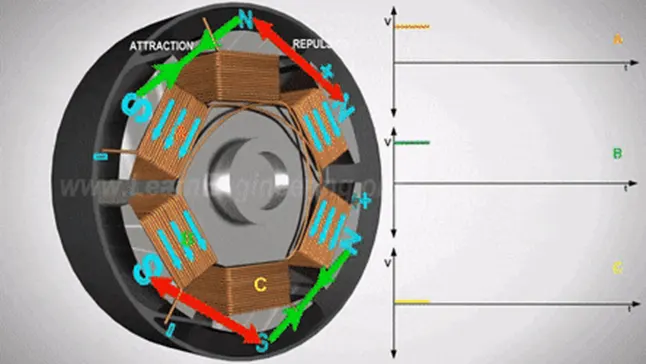
BLDC motor consists of rotor and the stator, the rotor consists of permanent magnet and the stator has a coil arrangement as shown in the given figure. They use electrical commutation to convert electricity into mechanical energy.
WORKING
When D.C current is applied to the coil the coil energizes and becomes an electromagnet. The operation behind the BLDC MOTOR is the force attraction between the permanent magnet and electromagnet. When coil A is energized the opposite poles of the rotor and stator are attracted each other. As the rotor reaches coil A coil B is energized and when the rotor reaches coil B coil C is energized after this coil A is energized with apposite polarity and the process is repeated and the rotor continues to rotate. The main drawback is that only one coil is energized which greatly reduces the power outcome of the motor. To overcome this problem you can energize the coil behind it which is coil B with the same polarity in such a way that there is attraction and repulsion of the rotor with respect to the coils which helps in giving constant torque and the power from the motor. In a BLDC motor a sensor is used which is a Hall Effect sensor which determines the position of the rotor and this information is sent to the electronic controller then decides which coil to be energized in order to achieve the required torque and power from the motor.
ADVANTAGES
- Maintenance is less and less noisy because of absence of brushes
- It has no mechanical commutator and associated problems
- Smaller motor geometry and lighter in weight as compared to brushed type D.C motor
APPLICATIONS
BLDC motors are used in many electronic devices like washing machine, air conditioner, compressors, fans, electric vehicles, hybrid vehicles and industrial robots because of their high efficiency and longevity