Week - 4
AIM:
- To implement control logic of a washing machine using state flow by giving certain condition as per power input and water input. As per this input, machine operates and obtains output by lamp light
- Create the state flow for gear shift and vary the speed as input and obtain as the gear number in display.
OBJECTIVE:
- To implement control logic of a ‘washing machine ’ using state flow as per given sequence :
- If the power supply is available , the system gets activated
- If the water supply is not available , stop the process and indicate through led
- Soaking time should be 200s followed by washing time of 100s
- Then rinsing happens for next 20s and dryer runs for 50s.
After all the process have completed turn on the finished LED.
- To make a Simulink chart for the ‘gear shift ‘ logic as per below conditions :
|
Speed range(kmph) |
Gear |
|
0 to 15 |
1 |
|
16 to 25 |
2 |
|
26 to 40 |
3 |
|
41 to 60 |
4 |
|
Above 61 |
5 |
Given speed input while the simulation is running and display the gear number.
STATEFLOW:
Stateflow is a control logic tool in which reactive systems are modelled via state machines and flow charts within a Simulink model. It provides a graphical language which includes transition of state diagrams, flow charts, state transition tables and truth tables. State flow helps to describe how matlab algorithms and Simulink models react to input signals, events and time – based conditions.
Stateflow helps to design and develop supervisory control, task scheduling, fault management, communication protocols, user interfaces and hybrid systems.
CONTROL LOGIC:
Control logic is an integral part of the software where the operations of the program are controlled. The control logic responds to commands from the user and also performs automated tasks on its own that has been structured into the program.
The applications for control logic include:
- The sequences of tasks and steps for a system are scheduled.
- Monitors how it switches between different modes of operation.
- It helps in defining faults detection, isolation and recovery logic.
WASHING MACHINE:
Washing machine is a home appliance which washes different types of clothes and for this various settings are provided. Washing powder is added by the user which is either in solid or liquid form to wash the clothes.
WORKING OF WASHING MACHINE:
- The following components that the washing machine include are:
- Water pump
- Water inlet control valve
- Drum
- Washing machine motor
- Drain pipe
- Printed circuit board
- Timer
- Heating element
- Firstly the clothes are put into the machine by the user and the detergent is added into the tray which is placed above.
- The program is set by the user and the power is switched on
- Once the power is supplied on water from the inlet inters the machine and fills the drum and there are sensor that senses how much water is required and usually the water enters from the top so as to introduce the detergent into the machine.
- Water valves is switched off by the programmer and soaking takes place for 200 sec.
- The drum rotates back and forth cleaning the clothes through the soapy water for 100 sec
- The detergent removes the dirt from the clothes and traps it in the water.
- The water from the drum is drained with the help of the pump.
- The water valves are opened again by the programmer so that clean water enters the drum.
- The drum is made to rotate back and forth again so that the water rinses the clothes. This process is repeated several times so as to get rid of the soap.
- During the process of rinsing the drum is made to rotate at a very high speed so as to extract as much as water from the clothes so as to reduce the drying time which makes clothes slightly damp rather than wet .
- Finally the pump removes remaining water from the drum and the washing cycle comes to an end.
- After 20 seconds of rinsing, drying action takes place for 50 seconds.
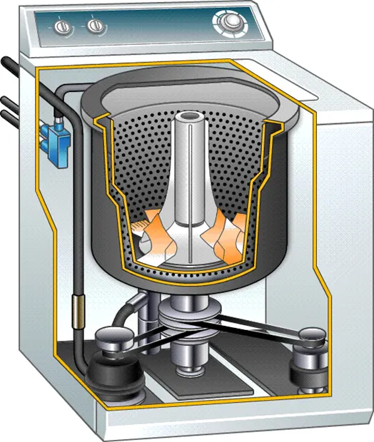
CONTROL LOGIC OF WASHING MACHINE AND EXPLANATION:
- The control system is created in Simulink by the chart block and the logic system is created using state flow.
- According to the control logic the input power is applied to ON the washing machine and the power supply flows in the other systems. The conditions are applied so as to move the sequence of operation in state flow.
- When the power is ON water supply is started, so entry and exit values are assigned as value of 0 or 1. IF condition is not OK water supply stops and returns to its original state.
- This process is applied for each flow and the working of each operation is initiated by seconds as given in the question.
- State flow of washing machine is created and shown below :
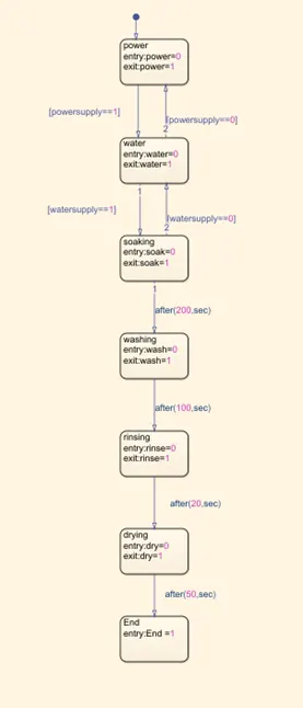
- The input and output for the stateflow is defined in symbol pane after making the blocks and defining transition statements as defined below :
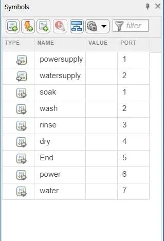
- Now the input values of steady flow is assigned and sequence of operation is initiated so as to identify the working division. Constant block is created so as to give input to the power supply for the system.
- Then another constant block is added for the input of water supply as 1 to run the washing sequence.
- Display block is connected to the chart next to each sequence so as to display the results of operations.
- Lamp block is introduced so as to indicate the on or off condition for each different state.


ON OFF
RESULTS:
Simulink model is created and inputs are assigned to power supply and water supply
- The power supply and the water supply values are assigned as 1 .Power is generated from the input and operation starts.
- When the condition gets satisfied the sequence of operation in stateflow starts. Water supply is commenced and other operations followed by the duration of time given as per the question.
- Each operation is run and the results are obtained in the display block.
As shown below the lamp is turned on green which indicates that all the result are satisfied:
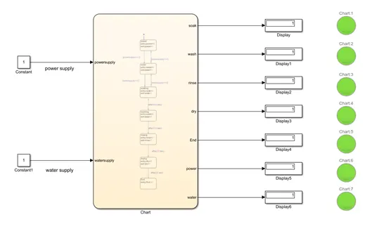
- In this state power supply is assigned as 1 and the water supply remains 0. The power is generated and shown in the display value as 1 and the lamp turns green. Since the water supply remains 0 other operations will not proceed further and all the lamps will turn red.
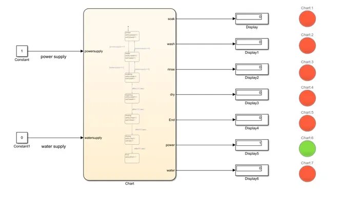
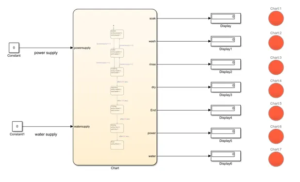
- If the power supply and water supply is assigned as 0 the output value of all the operations became zero because no inputs are generated and conditions are not satisfied.
As shown below the lamp is in red colour due to ‘off’ condition of operation system.
Theory:
Transmission is a mechanism that transmits power developed by the engine to the wheels of the car which is called as transmission system. For the vehicle to move forward at different speeds power changing devices is required to transfer the power developed by the engine to the wheels such devices are known as transmission.
The following are the Functions of gear box:
- Provides the much needed torque for the vehicle to move forward under road and load conditions.
- It can be shifted to reverse gear so that the vehicle can move backward.
- It is also shifted into neutral for starting the engine.
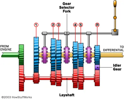
The Diagram above shows a basic transmission system which is connected to an engine shaft. This shaft is also connected to an another shaft (layshaft) with two gears .This layshaft is in turn connected to the differential drive shaft through a set of gears . The power from the engine shaft turns at a particular velocity which is revolutions per minute which in turn causes other shafts to turn which makes the vehicle move forward. These set of gears are designed in such a way that the vehicle moves at different speeds depending upon the gear given.
CONTROL LOGIC OF GEAR SHIFTING AND EXPLANATION:
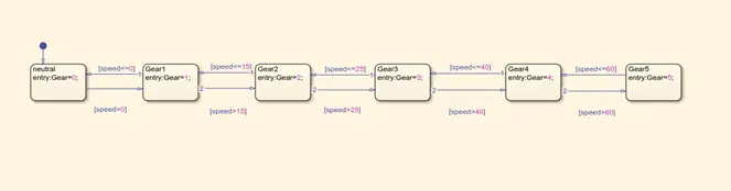
- Chart block is created which defines the state flow as per the given conditions.
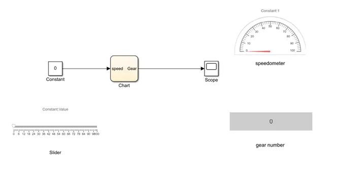
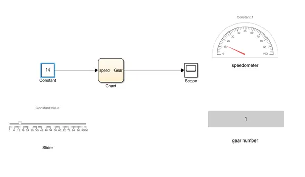
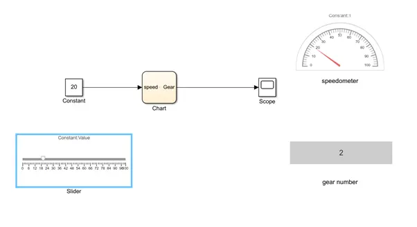
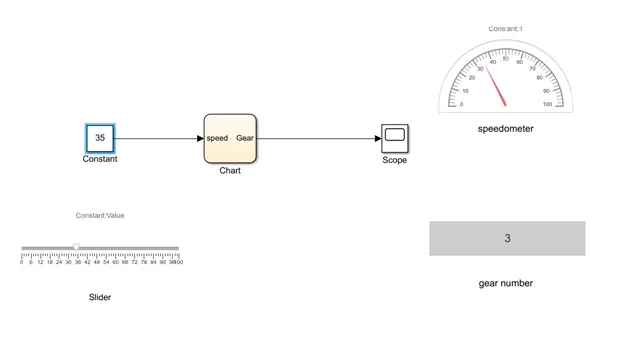
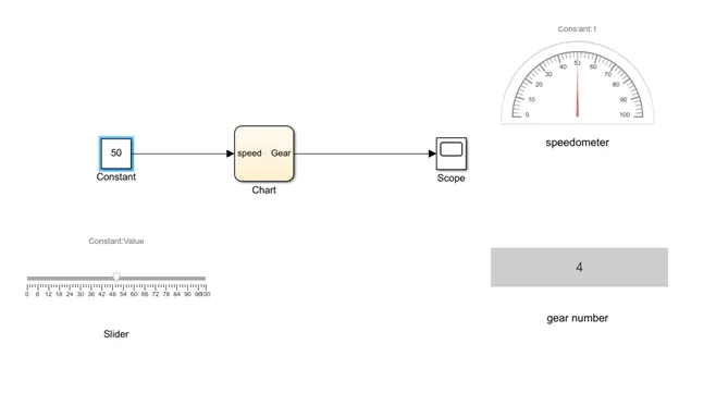
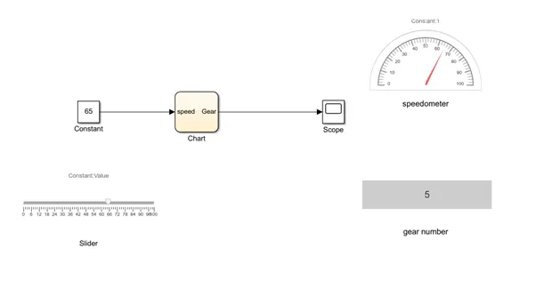
- In this model a constant block is connected in which speed values is assigned which is connected to the chart block to which a slider gain is connected. Gear shifts depending upon the variations in speed during the state flow.
- If the speed is between 0 and 15 it will be in 1st gear
- If the speed increases beyond 15 it will be in second gear and will remain in second gear between 16 to 25.
- If the speed increases beyond 25 it will be in third gear and will remain in third gear between 26 to 40.
- If the speed increases beyond 40 it will be in fourth gear and will remain in fourth gear between 41 to 60.
- If the speed goes beyond 60 it will be in fifth gear.
- Constant block is connected which is assigned as the input where the speed value is given whereas the speedometer, scope and gear number is displayed as outputs.
- Constant block is connected to the chart block and the slider switch and speedometer is connected to the constant block and gear block is connected to the scope so depending on the speed variation after you run the program the gear is displayed in the displayed block .
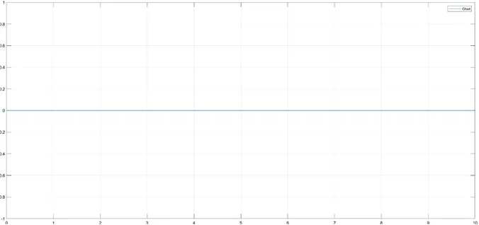
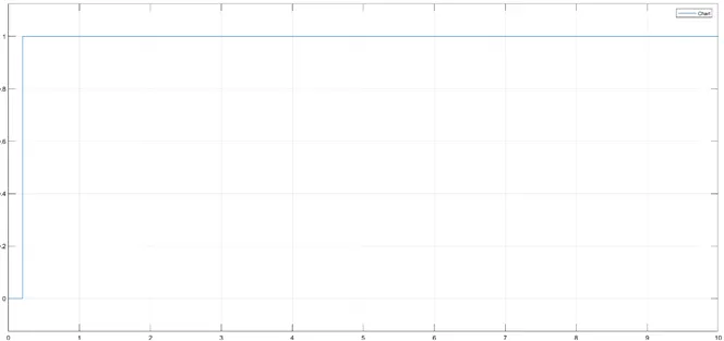
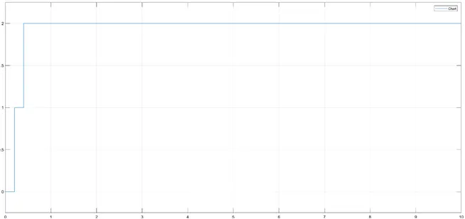
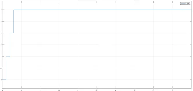
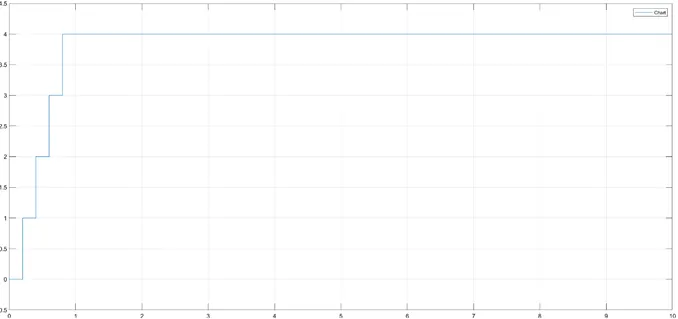
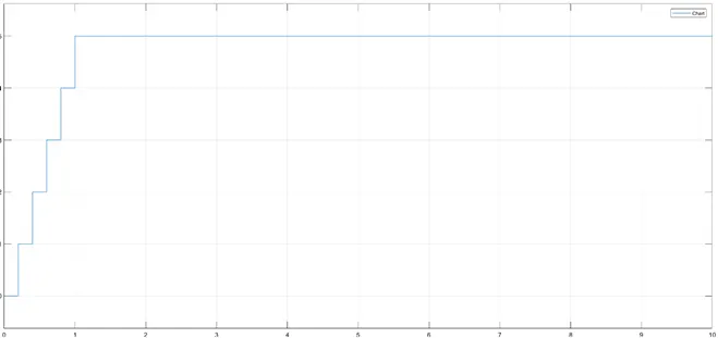
- Depending on the speed the gear is displayed in the display block and the scope provided gives the output plot.
RESULTS:
- Speed = 0, gear number =0
- Speed: 0 to 15 , gear number = 1
- Speed: 16 to 25 , gear number = 2
- Speed: 26 to 40 , gear number = 3
- Speed: 41 to 60 , gear number = 4
- Speed: Above 60 , gear number = 5
CONCLUSIONS:
- By giving the input as 1 to power supply and water supply all the conditions were satisfied and hence the sequence of operation of washing, rinsing and drying was carried out systematically and the stateflow was executed as per the given condition.
- It was observed that by changing the speed with respect to time the gear was changing and displayed in the display block and the stateflow was excuted as per the given condition.