Week -2
AIM :
- To make a simulink model of doorbell using solenoid block with the following details :
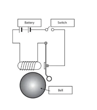
- In the below arrangement when the switch is closed the electromagnet recieves electrical power from the battery so that the metal arm is pulled .
- The switch is closed for a period of 2 seconds and released . the physical movement of the plunger is observed .
- To use a thermistor to sense the temperature of a heater and turn on or turn off the fan as per below conditions :
- Temperature source : 20°C from 0 to 10 seconds , 27°C from 10 to 30 seconds, 23°C from 30 to 50 seconds
- Fan conditions : ON if the temperature above 25°C, OFF otherwise .
THEORY :
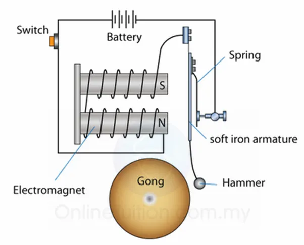
Doorbell is constructed using solenoid , battery, switch . In the circuit the current is supplied though the circuit from the battery source once the switch is closed . This means that the bell rings continously when the switch is closed . When the switch is closed , the current from the battery passes through the circuit and enters into the solenoid . Solenoid is a device which converts electrical energy into mechanical energy it is coil wound around a conductive material whch acts as an electromagnet when current passes through the coil . The current passing through the coils induces electromagnetism in the coils which forces the hammer towards the gong ( bell) which produces sound .
SIMULINK MODEL OF A DOOR BELL USING SOLENOID
EXPLANATION OF EACH BLOCK IN THE MODEL USED:
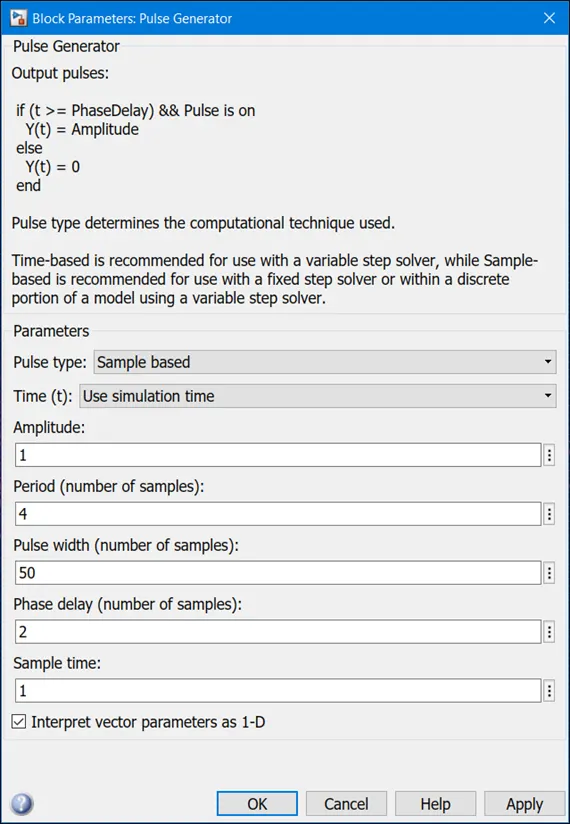
- Pulse generator block is a block in which at regular intervals square wave pulses are generated. The block waveform parameters, amplitude, pulse width, period and phase delay determine the shape of the output waveform. The below diagram depicts how each parameter effects the waveform.
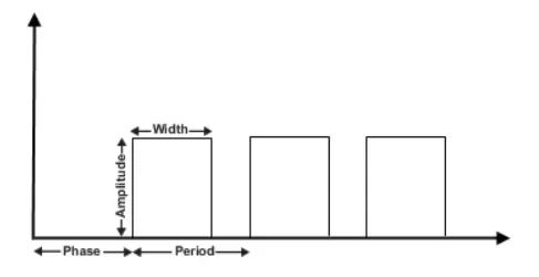
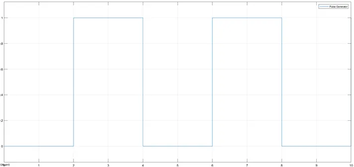
The condition given is that the bell closed for a period of 2 seconds and then released. To implement this condition a period of 4 seconds and pulse width (50% of 4 seconds) i.e 2 seconds . so a phase delay of 2 seconds is given such that the simulation can start when the switch is off.
- SWITCH
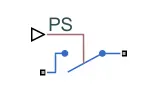
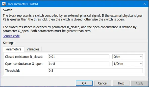
This switch block is controlled by an external physical signal. If the external physical signal (PS) is greater than the threshold, then the switch is closed, otherwise the switch is opened.
BATTERY
The positive terminal of the battery is connected to the switch and the negative terminal is connected to the electrical reference.
6.SOLENOID
Solenoid block is connected with the switch and battery and the complete electrical circuit is formed.
The figure below shows the electrical characteristics and generated force for the solenoid.
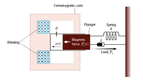
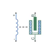
The return spring is optional .Since the effects of the spring from the model is removed, the spring constant parameter is set to θ. Port C is connected with mechanical translational reference.
7.IDEAL TRANSLATIONAL MOTION SENSOR
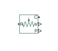
Ideal translational motion sensor is connected with solenoid block R so as to observe the movement of the plunger. Connections R and C are mechanical translational ports conserving ports which connects the block to the nodes where the motion is being monitored. Connections V and P are physical ports for velocity and position.
The block positive direction is from port R to port C. The velocity measured between these two ports is given as V = vR – vc , where vR – vc are absolute velocities at ports R and C .
Port C is connected to mechanical translational reference.
8.SCOPE:
Scope is connected to ideal translational motion sensor to get the output after the simulation is run. Scope is used for viewing the graphs of the signals.
9.SOLVER CONFIGURATION :
Each physical network is represented by connected simscape block diagram which requires solver settings information for simulation. Solver parameters are identified by solver configuration that your model need before you can run the simulation.
MODEL EXPLANATION
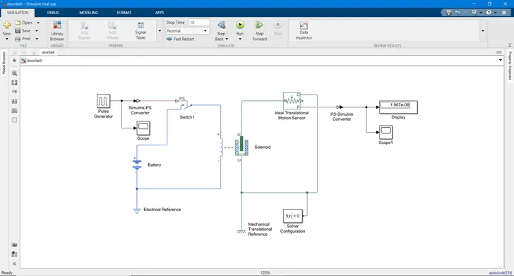
- Firstly the switch (electrical) is added to the model from the library browser. The switch contains 3 ports. The switch should be operated for 2 seconds. So to conduct this operation a pulse generator block is added with a phase delay of 2 seconds, amplitude 1 and phase width as 50% and time period of 4 seconds.
- Since the pulse generator is a Simulink model and the switch is a simscape model a Simulink –PS convertor is added so as to connect the pulse generator to the switch.
- Scope block is added to the pulse generator to know the input which is given to the pulse generator.
- Battery block is connected so as to supply current to the circuit via the switch.
- The current from the battery is supplied to the solenoid spring due to this the electromagnetism induced in the coils makes the plunger move into motion.
- To sense the motion of the plunger an ideal translation motion sensor is added. The point R of the Solenoid is joined with ‘R’ of the Ideal Translational Motion sensor and point P gives the position of the plunger.
- A mechanical translational reference block (represents a mechanical translational reference point that is a frame or ground that is rigidly affixed to the frame) connected to point C
- For knowing the position of the plunger a scope block is connected. A Simulink – PS is connected to convert physical form to Simulink form.
- Electrical reference is connected to the battery.
- A solver configuration block is added and joined with the circuit
- The whole circuit of the doorbell is ready for simulation
- The simulation is run for 10 seconds.
RESULTS:
INPUT SCOPE:
Below is the graph that shows the time and amplitude
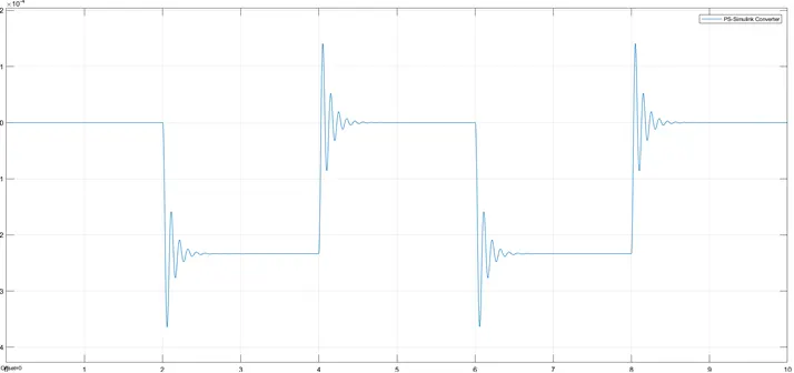
OUTPUT SCOPE:
The graph below shows that after 2 minutes there is disturbance.
2.THERMISTORS
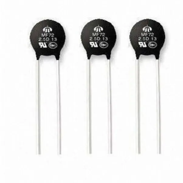
A Thermistor is a type of resistor whose resistance varies with temperature. There are two types of resistors viz.NTC (negative temperature coefficient) and PTC (positive temperature coefficient).
In case of negative temperature coefficient thermistor, when temperature increases resistance decreases and when temperature decreases resistance increases. This type of thermistor is mostly used.
A positive temperature coefficient thermistor works opposite as compared to NTC. When temperature increases the resistance increases, and when temperature decreases, resistance decreases. This type of thermistor is generally used as a fuse.
High precision within a limited temperature range is achieved for a thermistor. This range is dependent on the base resistance.
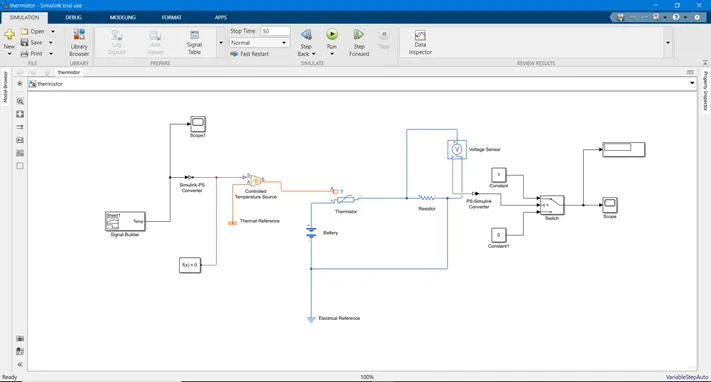
BLOCK DIAGRAM OF SIMULINK MODEL:
CIRCUIT CONNECTION OF THERMISTOR TO SENSE THE TEMPERATURE OF HEATER
EXPLANATION OF EACH BLOCK IN THE MODEL USED:
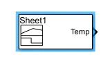
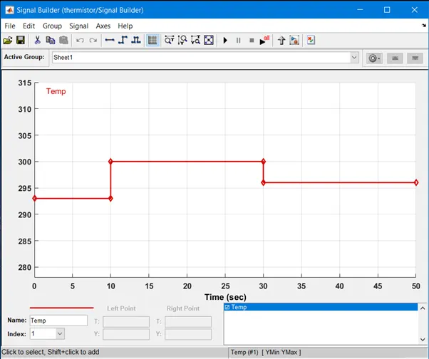
The signal builder helps to create interchangeable groups of piecewise linear signal sources which is used in the model. In signal builder window, signals are created and output wave forms are defined. In this case the input values are given as per the given condition.
GIVEN INPUTS:
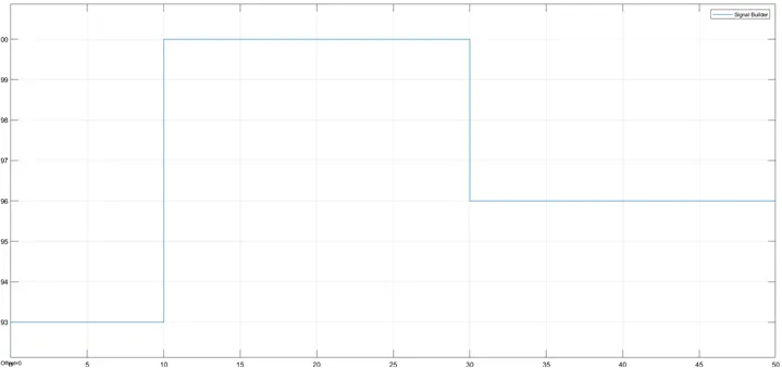
At point 1 - time 0 sec – temperature – 293k
At point 2- time 10 sec – temperature – 293k
At point 3 - time 10 sec – temperature – 300k
At point 4 - time 30 sec – temperature – 300k
At point 5 - time 30 sec – temperature – 296k
At point 6 - time 50 sec – temperature – 296k
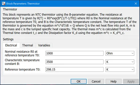
Now the input from the signal builder is connected to controlled temperature source. The output of the controlled temperature source is connected with thermistor. The thermistor block will show values as shown below:
- CONTROLLED TEMPERATURE SOURCE :
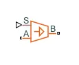
Controlled temperature source block represents an ideal source of thermal energy which is powerful to maintain specified temperature difference across the source regardless of the flow of heat consumed by the system.
Connections A and B are thermal conserving ports corresponding to the source inlet and outlet, respectively. Port S is a physical port, through which the control signal that drives the source is applied.
- THERMISTOR :
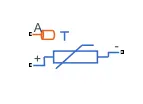
A Thermistor is a type of resistor whose resistance varies with temperature. The word thermistor means a combination of thermal and resistor.
Thermistor block represents an NTC thermistor using the B- parameter equation.
RESISTOR :
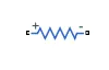
Resistor block models a linear resistor, it is given by the following equation
V=IR
Where,
V = voltage
I = current
R = resistance
VOLTAGE SENSOR :
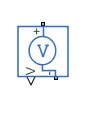
Voltage sensor block represents an ideal voltage sensor is a device that converts voltage measured between two points of an electrical circuit into physical signal proportional to voltage.
- BATTERY:
The positive terminal of the battery is connected to thermistor and the negative part is connected to the resistance.
- ELECTRICAL REFERNCE :

The electrical reference block represents an electrical ground. Electrical conserving ports of all the blocks that is directly connected to the ground must be connected to an electrical reference block.
- SWITCH :
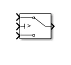
Based on the value of the second input the switch block passes through the first or the third input signal. The first and third inputs are data inputs. The second input is a control input.
MODEL EXPLANATION:
- Temperature inputs are given in kelvin as per the data from excel sheet.
|
|
||||||||||||||
- Signal builder is added so to input the given temperature as per sample time.
- Scope is connected to the signal builder so as to get the input plot of the signal.
- Controlled temperature source block is connected so as to maintain temperature. Now the signal builder is connected to controlled temperature block with the help of Simulink –PS convertor to point S.
- Thermal reference block is added to point A of the controlled temperature source.
- Thermistor block of point ‘A’ is connected to point ‘B’ of the controlled temperature source block.
- Battery block is added so to pass the current throughout the circuit.
- Now the voltage sensor block and resistor is connected to the thermistor so as to complete the circuit and to this an electric reference block is connected.
- Since the fan needs to be operated under on and off condition, a switch block is connected with inputs. Inputs given are 0 and 1 with two constant blocks.
- Voltage sensor is connected to the switch with the help of PS – Simulink convertor. The switch operates in values between 0 and 1.
- Display block is connected so as to know the threshold value and is also joined with the switch. Scope block is added so to know the output of the signal from the switch.
- Solver configuration block is added
- The model is run for a simulation of 50 seconds so that to get the output of the signal.
RESULTS:
INPUT SCOPE:
The graph shown below is the plot of time v/s temperature and shows the condition of fan operating with time with respect to temperature.
OUTPUT SCOPE:
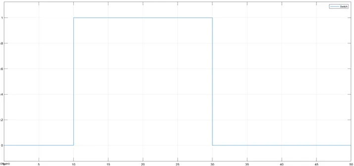
The graph shown below depicts the on and off condition of fan at a period of 50 seconds.
CONCLUSION:
- We can conclude by saying that when the switch is closed the current from the battery passes through the solenoid which acts as an electromagnet and pulls the plunger to hit the bell to produce the ringing sound .
The motion of the plunger is stimulated recorded and plotted by using an ideal motion sensor and scope.
- Thermistor is used to sense the temperature of heater and turn on or off the fan as per the given conditions
Therefore the conditions of fan are executed by the switch block and plotted in the scope.