DC Motor Control
Aims:
- To run MATLAB demo ‘Speed control of a DC motor using BJT H-bridge’. Modify the model such that armature current does not shoot up when motor changes direction from forward to reverse.
- To compare The Four-Quadrant Chopper DC Drive (DC7) block with H-bridge model.
- To make a suitable EV model using DC7 block and make result report.
Theory:
Part 1: To run MATLAB demo ‘Speed control of a DC motor using BJT H-bridge’.
Transistors: These are devices which have controlled turn on and turn off characteristics. Transistors are used as a switching devices and are operated in the saturation region resulting in low on state voltage drop. They are turned on whenever a current signal is given to base control terminal
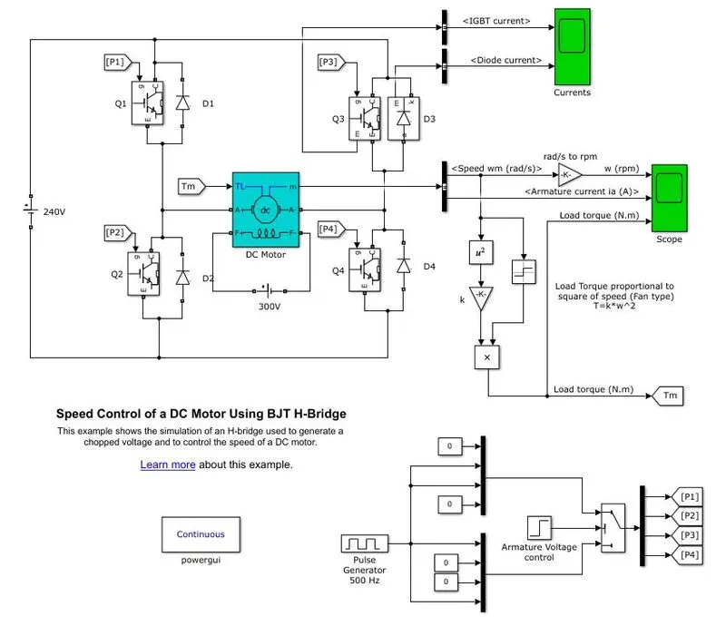
BJT:As shown above the model has an H-bridge which is used to generate a chopped voltage and control the DC motor. This model has a bipolar junction transfer BJT as the power switching application operated as IGBT. The two transistors keeps switching simultaneously that is from Q1 and Q4 or Q2 and Q3. Whenever Q1 and Q4 are active, a positive voltage is given to the motor and diodes D2 and D3 operate as free wheeling diodes when Q1 and Q4 are switched off. Whenever Q2 and Q3 are active, a negative voltage is given to the motor and diodes D1 and D4 operate as freewheeling diodes when Q1 and Q4 are switched off. The typical characteristics of a BJT are that, it is a large sized device, hence maximum current can flow through it. The breakdown voltage is high. BJT has higher on-state voltage drop and is a high power application device.
IGBT: It is a combination of BJT and FET whose function is based on its gate where the transistor can be turned off or on depending upon the gate. These are commonly used in power electronics devices such as invertors, power supply and converters.
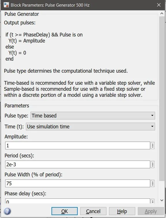
For simulation the armature voltage can be varied from 0 to 240 V and the duty cycle can be varied from 0 to 100%, the default set duty cycle in the model is 75% as shown in the figure below.
Simulation:
The default simulation parameters are as follows:
- Power: 5 HP
- Rated Motor Speed: 1750 RPM
- Motor starts in +ve direction with the duty cycle of 75%.
- Rated Voltage: 240 V
The default simulation output can be seen below:
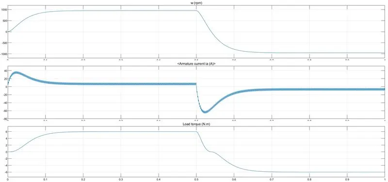
From above plot we can say that
- From the motor speed against time plot, speed is proportional to the applied load torque. Speed of 950 RPM was observed.
- Armature current drawn at each instant; a spike of current is observed in the armature.
- In load torque against time plot, 6 Nm of torque is applied initially to motor at time instance t = 0.5, the rotation direction is observed as reversed direction and a negative torque is observed of similar magnitude.
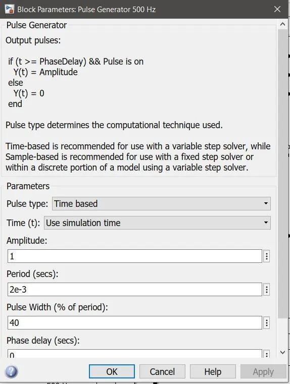
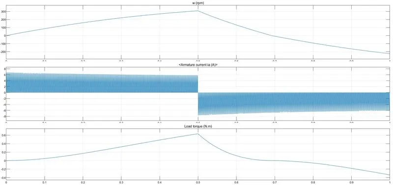
Thereafter the duty cycle ratio was changed from 75% to 40% and the following plot and observations were noted:
Observations:
- The load speed is reduced from 950 to 308 RPM.
- The reduction in duty cycle ratio resulted in the stable armature current therefore the shoot-up can be optimised.
- The load torque was reduced considerably from 6 Nm to 0.63 Nm.
- There is considerable fall in load torque and hence speed.
Conclusion:
By reducing the duty cycle ratio of the power modules results in ultimate reduction of shooting armature current however reduces the supply voltage to the motor and results in the reducing the speed and torque of the motor.
Part 2: Comparing the Four-Quadrant Chopper DC Drive (DC7) block with H-bridge model.
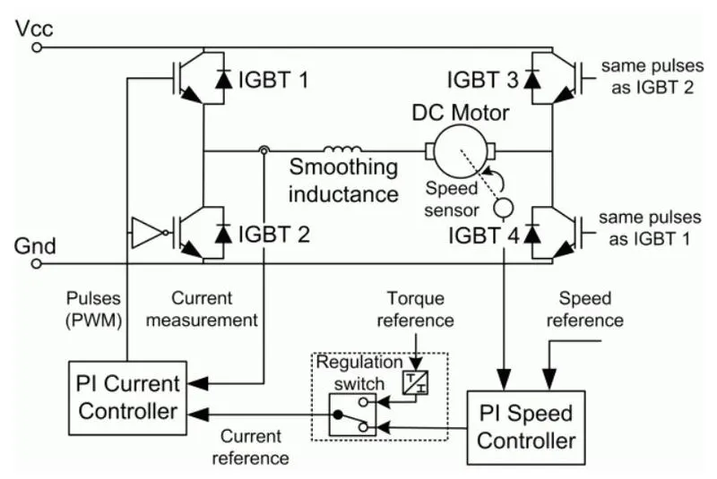
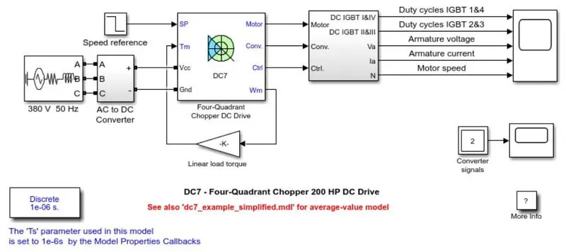
Above shown is the Four-Quadrant Chopper DC Drive. It uses the blocks from the electric drives/ fundamental drives blocks from the Simulink library which are: Speed Controller, Regulation Switch, Current Controller and Chopper. This is the DC-DC converter chopper drive for DC motors which features a closed loop speed control with four quadrant operation. The speed control loop outputs the reference armature current of the motor. Using PI current controller, the chopper duty cycle corresponding to the commanded armature current is derived. This duty cycle is then compared with a sawtooth carrier signal to obtain the required pulse with modulus signals for the chopper.
The 200 HP DC motor is separately excited with a constant 150 V DC field voltage source. The armature voltage is provided by an IGBT converter controlled by two PI regulators. The converter is fed by a 515 V DC bus obtained by rectification of a 380 V AC 50 Hz voltage source. In order to limit the DC bus voltage during dynamic braking mode, a braking chopper has been added between the diode rectifier and the DC7 block.
The first regulator is a speed regulator, followed by a current regulator. The speed regulator outputs the armature current reference (in p.u.) used by the current controller in order to obtain the electromagnetic torque needed to reach the desired speed. The speed reference change rate follows acceleration and deceleration ramps in order to avoid sudden reference changes that could cause armature over-current and destabilize the system. The current regulator controls the armature current by computing the appropriate duty ratios of the 5 kHz pulses of the four IGBT devices (Pulse Width Modulation). For proper system behaviour, the instantaneous pulse values of IGBT devices 1 and 4 are opposite to those of IGBT devices 2 and 3. This generates the average armature voltage needed to obtain the desired armature current. In order to limit the amplitude of the current oscillations, a smoothing inductance is placed in series with the armature circuit. Below is the figure [2] showing the DC7 chopper circuit connected with the motor.
H-Bridge:
Below shown is the figure [3] of H-Bridge circuit with the direction of the flow.
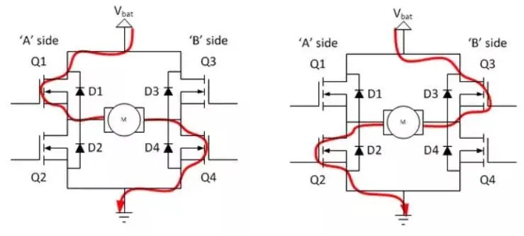
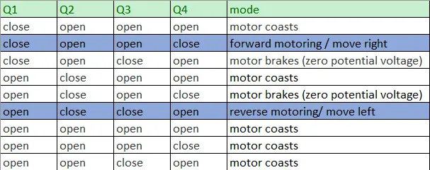
The H-bridge circuit could be used to operate an electrical DC motor in both forward and reversed manner as shown in the diagram. The table below shows all the possible states that the H-bridge could operate the motor in. The highlighted rows are the states that would drive the motor in a forward and in a reversed direction. For the states in which the motor coasts, this occurs because the circuit is not connected completely (only one switch is turned on). This leaves the motor unaffected by the power supply from the source of the H-bridge. Therefore, the motor coasts.
For the states in which the motor brakes, this occurs because the voltage difference between both terminals of the motor is zero [3].
Comparison of DC7 chopper and H-Bridge:
- The four quadrant chopper uses reference speed to change direction of motor rotation where H-bridge needs to reverse polarity to change the direction.
- PI controllers are used for speed and current control in the DC& chopper which is absent in H-bridge.
- The current shoot-up chances are relatively high in H-bridge because of switching losses.
- The four quadrant DC drive operates in four modes namely forward direction, reverse direction, forward braking, and reverse braking additionally it can also perform regenerative braking. However, the H-bridge can only perform forward and reverse direction operations.
Part 3: To make a suitable EV model using DC7 block and make result report.
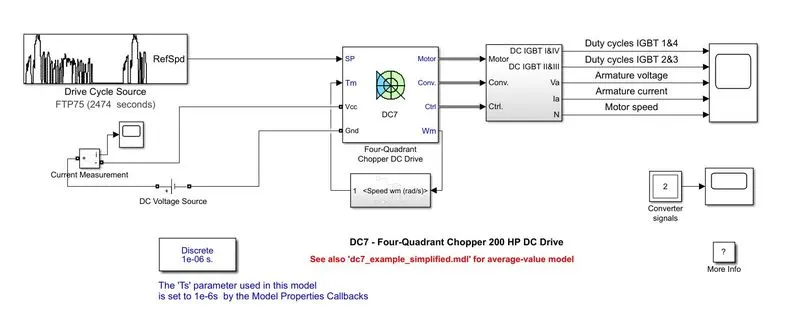
The EV model was made using the DC7 model shown in the previous part, however, some suitable changes had to be made in order to simulate it which are as follows:
- The 380V 50 Hz and AC to DC converter had to be replaced by a DC supply with the current measurement block linked with a scope to look at the input supply.
- The torque source input block was replaced with the defined torque equation which is:
- The speed reference block was replaced by the drive cycle block which was kept default at FTP75.
- The simulation was then run for 2 secs.
The model of the EV can be seen below with the changes made in the model.
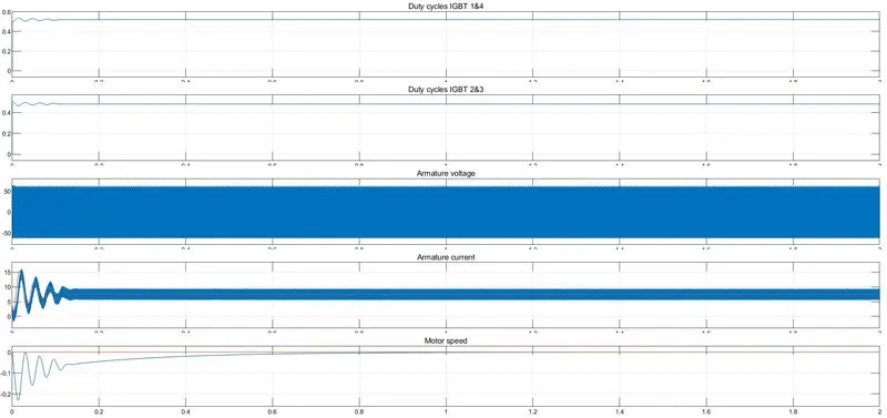
The output plot of Duty cycle od IGBT 1, 2, 3, and 4, Armature voltage, Armature Current and Motor Speed can be seen below.
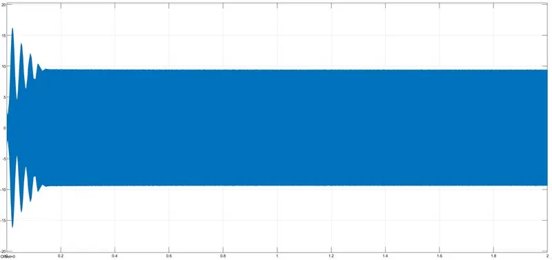
The input voltage supply plot can be seen below:
Conclusions:
- The Matlab model of Speed control of a DC motor using BJT H-bridge was ran successfully by making changes hence the armature current did not shoot. By reducing the duty cycle ratio of the power modules results in ultimate reduction of shooting armature current however reduces the supply voltage to the motor and results in the reducing the speed and torque of the motor.
- The comparison of Four-Quadrant Chopper DC Drive (DC7) block with H-bridge was done successfully.
- The EV modelled using DC7 block and was ran successfully with the output plot shown.
References:
[1] https://in.mathworks.com/help/physmod/sps/powersys/ref/fourquadrantchopperdcdrive.html
[2] https://in.mathworks.com/help/physmod/sps/ug/dc7-four-quadrant-chopper-200-hp-dc-drive.html?searchHighlight=The%20Four-Quadrant%20Chopper%20DC%20Drive%20%28DC7%29%20block&s_tid=srchtitle
[3] https://www.quora.com/What-is-the-working-of-a-H-bridge-circuit