Simulation of Doorbell using Solenoid and working of a Fan under different temperatures using a Thermistor
Aim:
- To simulate a Simulink model of a Doorbell using Solenoid block.
- To simulate working of a fan under different conditions using a Thermistor in Simulink.
Objective:
- To create a situation where the switch is closed for 2 seconds and then released. To observe the physical movement of the plunger.
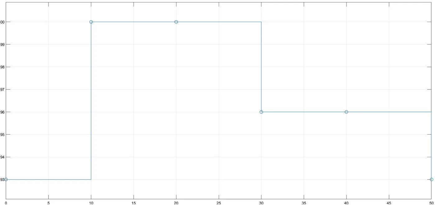
- To turn on the fan if the temperature is above 25 °C else off. To use the temperature source to simulate temperatures, from 0 to 10 seconds at 20°C, from 10 to 30 seconds at 27°C and from 30 to 50 seconds at 23°C.
Theory:
Part 1: Doorbell
A simple construction of a doorbell is as shown in the figure [1] below.
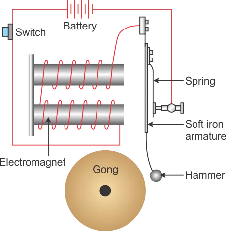
When the switch is pressed the circuit is completed and the electromagnet is activated which makes the hammer strike the bell. The armature is made of iron which attracts the magnet when the circuit is completed. This hammer is an iron ball that strikes on the bell. The iron armature is connected to the spring which maintains its position and not always in contact with the bell.
Solenoid:
A solenoid is nothing, but a copper wire wounded around the solenoid iron core which turns into a magnet when electricity is passed through it. The iron core demagnetises once the electricity is cut off [2]. A simple solenoid construction is shown in the figure below.
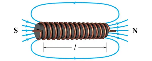
A solenoid is used in various fields such as in electrical appliances, automotive and aerospace applications, heavy machinery applications and much more. Solenoids are very beneficial as it has a very compact design plus having a controlled magnetic field which is only activated once the electricity is passed through it. The wire wrapped around the cylinder, the magnetic field because of the wires can become quite strong. More number of loops of wire stronger the magnetic field created. The formulae [3] for the magnetic field created inside the solenoid is as below:
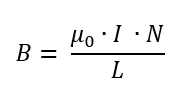
Where,
B = magnetic field (N/Amp m)
μ0 = permeability of free space
I = current (Amp)
N = number of loops
L = length of the solenoid
Simulink model procedure:
The Simulink model for Doorbell according to given conditions is as shown below.
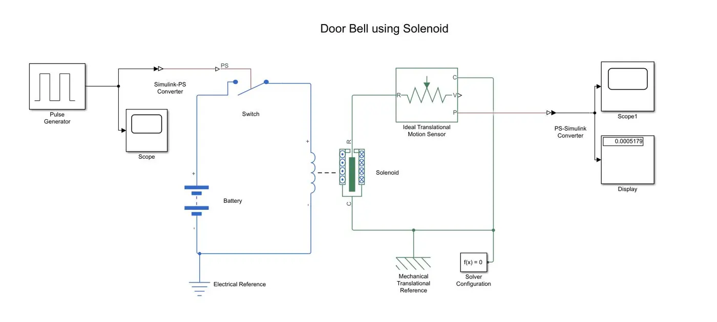
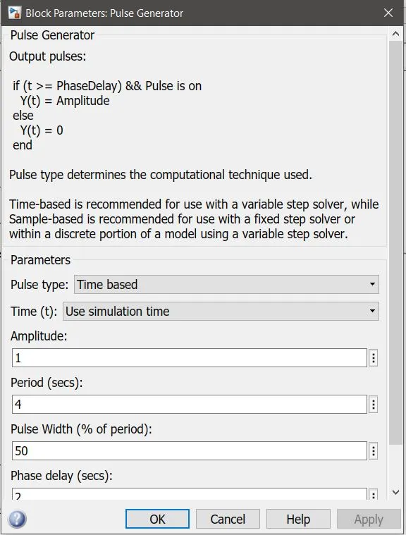
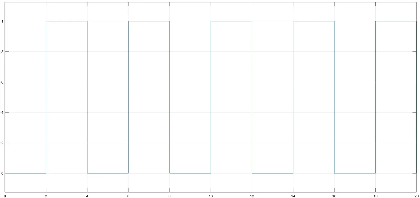
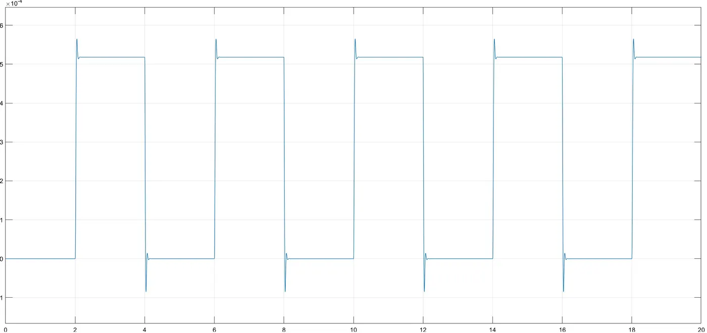
A pulse generator was used to generate pulse, where a switch is closed for 2 seconds and then released. A total of five pulses were given in the time span of 20 seconds. As shown in the pulse generator configurator figure below, the amplitude is kept 1, the total period of one pulse is kept at 4 seconds, pulse width 50% and phase delay of 2 seconds was given. The pulse type was selected as time based as the time set for the simulation to run was set as 20 seconds.
Thereafter a Simulink to PS converter was added in the model to convert Simulink input signals to a physical signal. A scope was added to the connection to observe the input pulses to the circuit. The input pulses can be seen in the plot below.
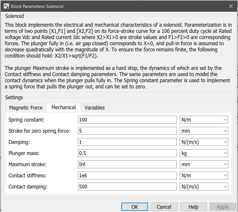
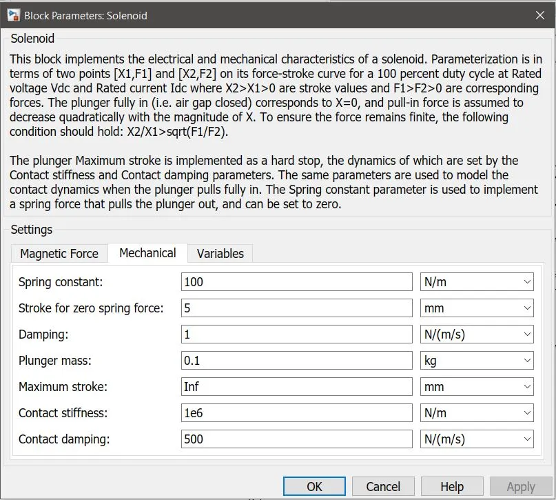
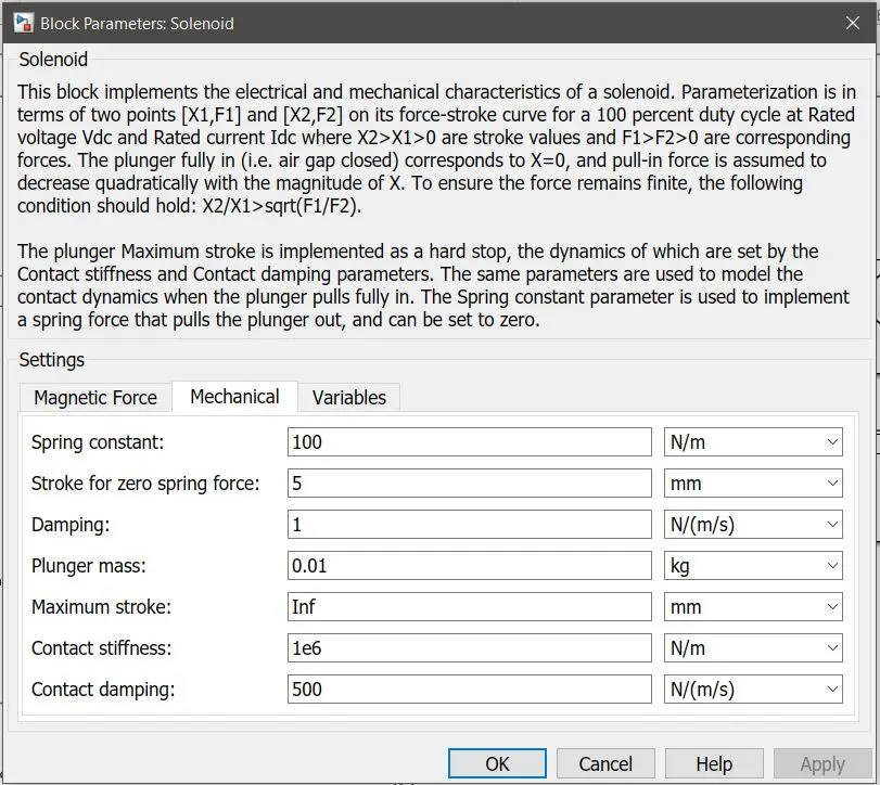
The Simulink to PS converter was then connected to the switch which had to be turned off and on to activate and deactivate the solenoid. This circuit was connected to the battery which is a 12 V battery. An electrical reference was attached to the circuit, which acts as an electrical ground of the circuit. Thereafter the solenoid was connected to the circuit for which the spring constant was set at 100 N/m, and then the plunger mass was set default at 0.05 kg, however it was changed at 0.01, 0.1 and 0.5 kg to study the damping of the spring at different plunger weights. The output of which is discussed in the result section of this study. The positive and negative terminals of the battery were connected to the positive and negative terminals of the loop windings of the solenoid. The R and C ports of the solenoid were connected to the R and C ports of the mechanical motion sensor.
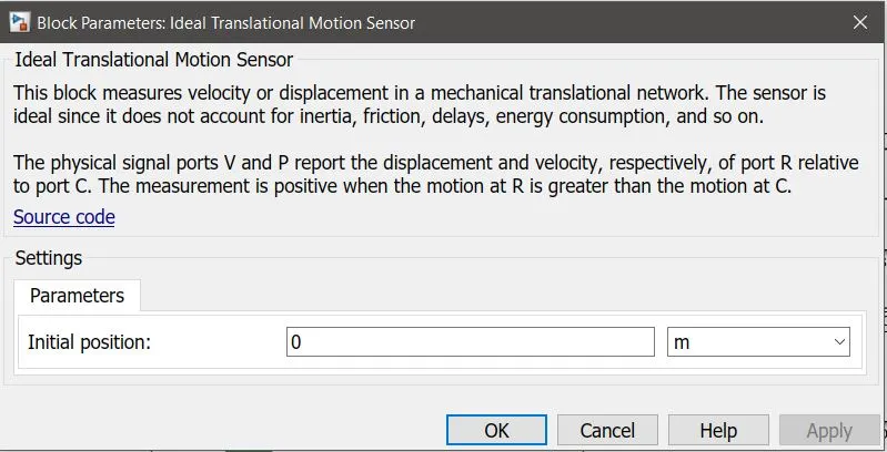
An Ideal Translation Motion Sensor was attached to sense the motion of the plunger of the solenoid. Of which the initial position was set at zero as shown in the figure below.
A mechanical translation reference was attached to the circuit as it represents a reference point, or frame, for all mechanical translational ports. A solver configuration block was attached at this circuit as it defines the solver settings of the information for simulation. Each and every Simscape circuit needs to be attached with the solver configuration block as it specifies the solver parameters that the model needs before beginning the simulation. Thereafter the PS to Simulink converter was attached to the circuit to convert the physical signals to Simulink signals to observe the outputs. The outputs were then observed at the scope and the display attached at the end of the circuit.
Results of Study 1:
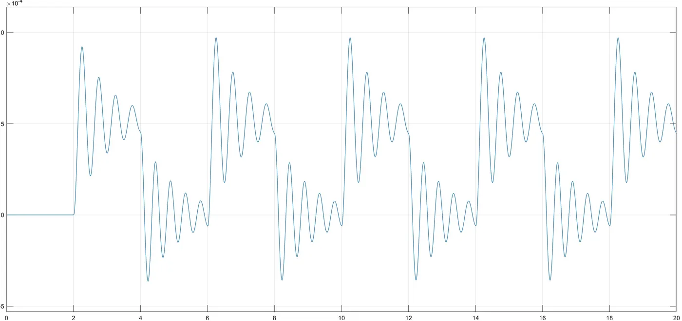
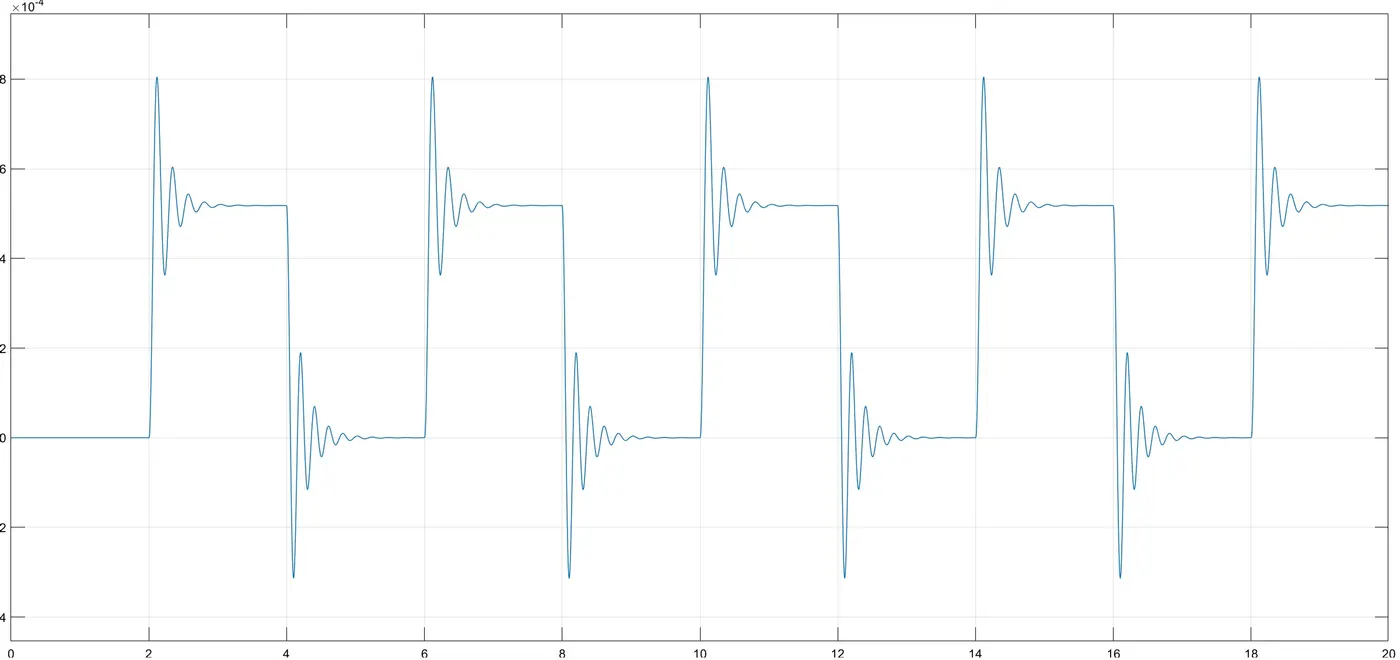
Three different scope plots as shown below for three different plunger weights. As seen in the plot of the plunger weighing 0.5 kg has larger deflection when compared to the plunger weighing 0.1 kg and very minute deflection in 0.01 kg plunger. Here we can see very less fluctuation as compared to the previous plots.
Plot for plunger weight 0.5 kg
Plot for plunger weight 0.1 kg
Plot for plunger weight 0.01 kg
From the above graphs we can say that by decreasing the plunger weight we get less deflection as the damping increases.
From these plots we can say that whenever the electric pulse was given to the solenoid the magnetic field was generated in the plunger struck and a deflection was seen in the motion sensor which reflects in the graph. Therefore, the study was a success, and the pulse deflections were observed in the output scope.
Part 2: Turn on a Fan using Thermistor
In this study a thermistor acts as an important block to sense the temperature according to the given inputs to turn on and turn off the fan if the temperature is above certain temperature and off if it is at certain environment temperature. The given conditions for the temperatures for this study were: from 0 to 10 seconds at 20°C, from 10 to 30 seconds at 27°C and from 30 to 50 seconds at 23°C. The fan has to turn on when the temperature goes above 25°C.
Thermistor: Thermistor is a thermally sensitive resistor which exhibits a precise and predictable change in resistance proportional to small changes in the surrounding temperature. The word “Thermistor” is derived from “thermally sensitive resistor”, whose resistance change with the change in temperature. Thermistors are very sensitive to the change in temperature therefore they are perfect to detect the changes in the temperature while recording the temperature or to operate electrical appliances such as AC, fan, oven, automotive and aerospace applications. There are a vast range of applications where thermistors can be used, and different sizes and shapes of thermistors are available in the market depending upon the applications. There are mainly two types of thermistors, NTC and PTC [4].
NTC: Negative Temperature Coefficient Thermistor
PTC: Positive Temperature Coefficient Thermistor.
In this study NTC type thermistor is used. This thermistor uses the B-parameter equation, where the resistance at temperature T is given by
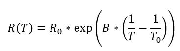
Where,
R0 = nominal resistance at the reference temperature
T0 = reference temperature
B = characteristic temperature constant
T = sensed temperature
The default values of R0, T0, and B in the thermistor block of Simulink are 1000 Ω, 298.15 K, and 3500 K, respectively.
Simulink model procedure:
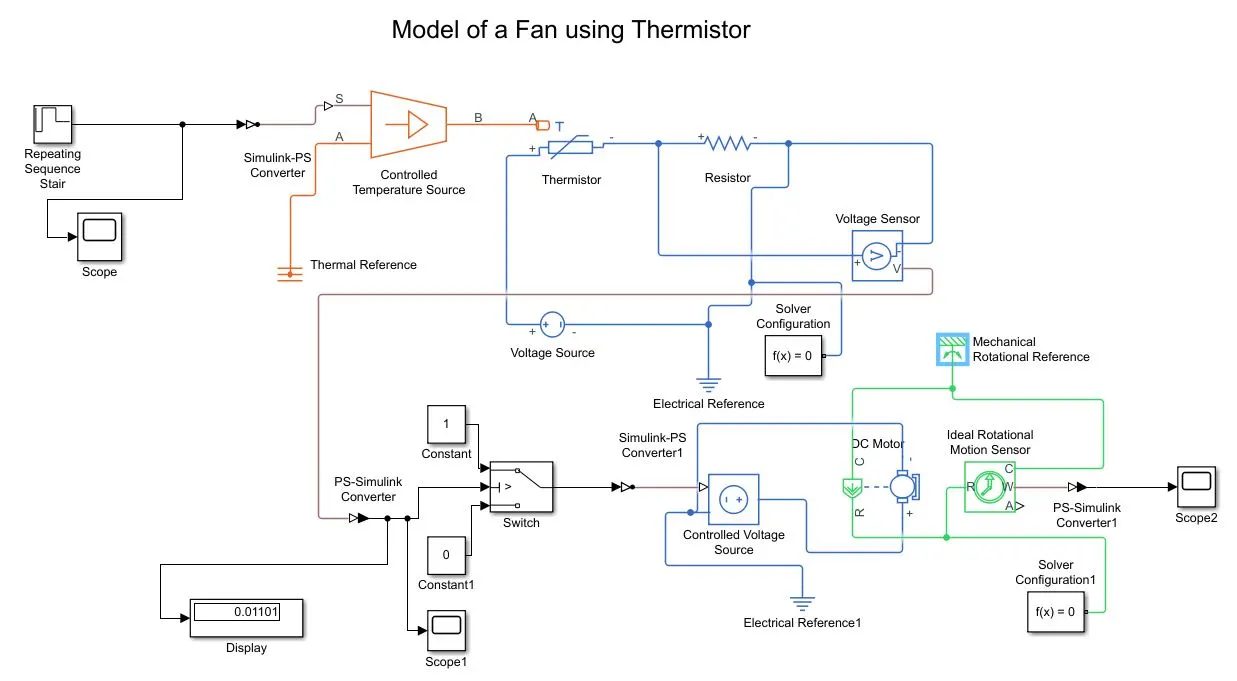
The Simulink model for this study can be seen below.
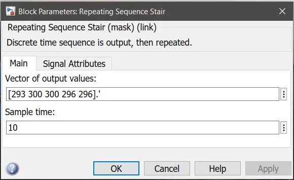
A Repeating Sequence Stair block was added while starting to model the circuit. This block provides the temperature pulses to the thermistor to sense the temperature before passing on to the switch weather to turn on or off the fan, these input signals were manually provided in the Simulink block which can be seen below with a sample time of 10 seconds, which means each temperature was given a time of 10 seconds.
A scope was attached to the circuit to observe the input signals to the circuit, as in the figure below. Thereafter a Simulink to PS converter was added to convert Simulink signals to physical signals.
Thereafter, a controlled temperature source was added to the circuit as it is an ideal source of thermal energy that is powerful enough to maintain specified temperature difference across the source regardless of the heat flow consumed by the system [5]. Port A was connected to the thermal reference, which represents a reference point to a thermal network where the temperature is equal to absolute zero.
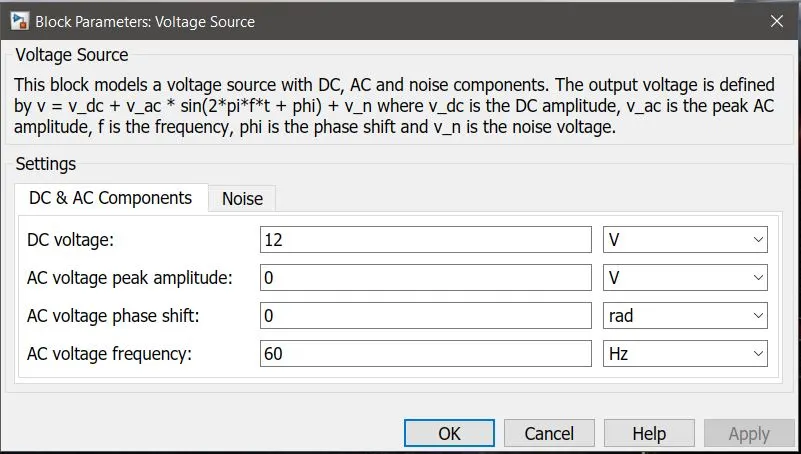
An NTC Thermistor was added after the controlled temperature source to the circuit where it was connected to port B of the controlled temperature source to Port A of the thermistor. A resistor was added in series to the thermistor with a voltage sensor to sense the output variation of voltage coming from the thermistor, the voltage fluctuation can be noticed with the fluctuation of temperature coming from the sequence stair block, which was then given the output to the Switch via port V. A voltage source was added to the circuit as it provides electricity to the circuit, this voltage source gives out the Voltage of 12 V DC. A solver configuration block was added to this circuit.
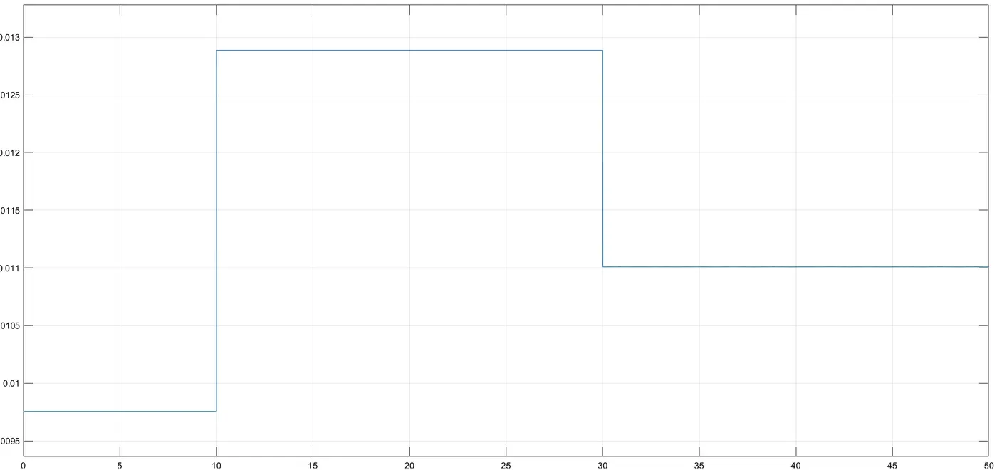
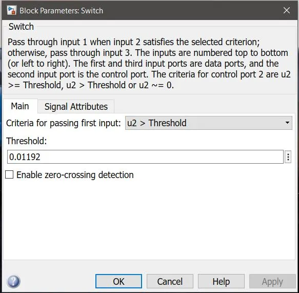
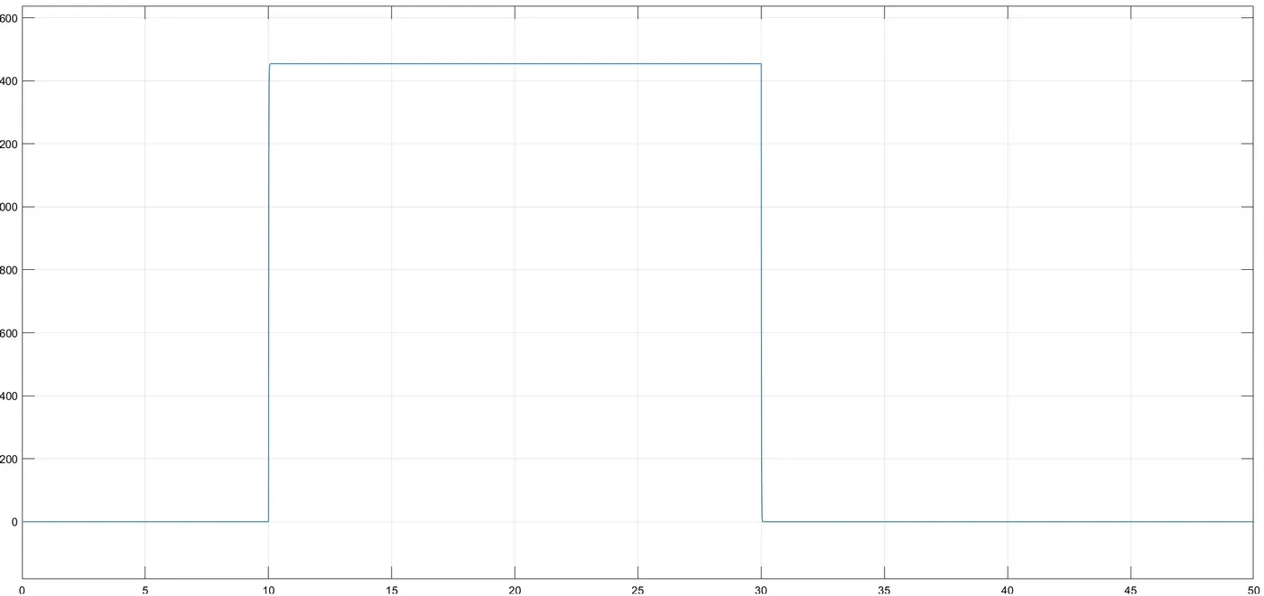
Thereafter a PS to Simulink converter was added before connecting voltage sensor to the switch as Simulink will not sense the physical signals. Thereafter the switch was given 0 and 1 constant inputs that if there is any signal to the switch the pulse will be 1 or else 0. A scope (as seen below) and a display were attached at this point to observe the signals coming to the switch, also to observe the 01101 output which is going to the switch asking the switch to turn on and off. The switch threshold was calculated initially before connecting the sequence stair block which was measured at the display output, this was calculated at 25°C, as the condition says if the temperature rises above 25°C the switch has to open or else it closes. Therefore, this threshold limit (0.01192) defines where to turn on and off the switch, which can be seen below.
Once again a Simulink to PS converter was added to the circuit as further in the circuit, a DC motor was added which acted as a fan in the circuit. After the Simulink to PS converter, the controlled voltage source was added to turn on and off the DC Motor. An electrical reference was added which acted as a ground to the circuit. Thereafter an Ideal Rotational Motion Sensor was added and was connected to R and C ports of the DC Motor. A mechanical rotational reference was added to the circuit, this is used to connect mechanical rotational ports that are rigidly affixed to the frame. Once again a solver configuration block was added as it is a different Simscape physical circuit and not a Simulink circuit. In the end the PS to Simulink was added to observe the output pulses from the DC Motor which can be seen in the results section.
Result:
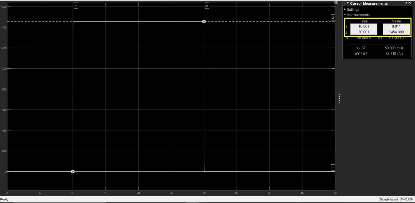
An output scope plot shown below depicts that when the temperature reached above 25°C, the DC Motor representing the fan was off for initial 10 seconds and then started working at 10th second showing around 1454.399 RPM of the motor and then, the motor turned off after 20 seconds at 30th second for the remaining 20 seconds of the time till 50th second.
As seen in the scope plot below we can see the turn on and turn off of the DC Motor highlighted in yellow box.
Conclusion:
It can be concluded that both the studies were a success where outputs observed were:
- When a doorbell rang, a deflection was observed in the scope plot.
- When the DC motor turned on and off when there was temperature difference was noticed by the thermistor and the switch and the RPM of the motor was observed in the scope plot in the end.
References:
[1] https://images.app.goo.gl/pjSD3QZhiBNo1vVL9
[2] http://www.solenoidsupplier.com/what-is-solenoid/
[3] https://en.wikipedia.org/wiki/Solenoid
[4] https://circuitglobe.com/thermistor.html
[5] Simscape / Foundation Library / Thermal / Thermal Sources