Week-7 Challenge: DC Motor Control
- SPEED CONTROL OF A DC MOTOR USING BJT H-BRIDGE:
- AIM:
The main aim of the project is to modify the model such that armature current doesn't shootup when motor changes direction from froward to reverse.
- OBJECTIVE:
BIPOLAR JUNCTION TRANSISTOR(BJT):
Bipolar Junction Transistor (BJT) is a type of transistor that uses electrons and electrons holes as charge carriers.A bipolar transistor allows small current injected at one of its terminals to control a much larger current flowing between two terminals,making the device capable of amplification or switching.A BJT consists of three differently doped semiconductor regions:the emitter region,the base region and the collector region.These are respectively,p-type,n-type,p-type in a PNP transistor and n-type,p-type,n-type in a NPN transistor.Each semiconductor region is connected to a terminal labeled as :emitter(E),base(B),and collector(C).
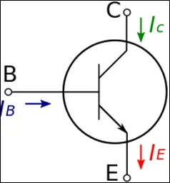
The BJT when used for power switching application,operates as an Insulated Gate Bipolar Transistor(IGBT).
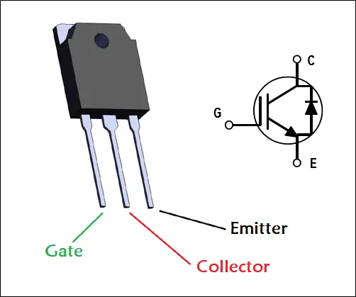
INSULATED GATE BIPOLAR TRANSISTOR(IGBT):
An insulated gate bipolar transistor (IGBT) is a three terminal power semiconductor device priarily used as an electronic switch which,as it was developed came to combine high efficiency and fast switching.Although the structure of IGBT is same as thyristor with MOS gate,the thyristor action is completely suppressed and only the transistor action is permitted in the entire device operation range.Ith is used in switching power supplies in high power application,variable frequency drive(VFD),electric cars,trains,variable speed refrigerators,lamp ballasts,arc-welding machines,and air-conditioners.The IGBT combines the simple gate-drive characteristics of power MOSFETs with high current and low saturation voltage capability of bipolar transistor.The IGBT combines an isolated gate FET for the control pf input and a bipolar power transistor as a switch in single device.The IGBT used in medium to high power applications like switched mode power supplies,traction motor control and induction heating.Large IGBT modules typically consists of many devices in parallel and can heve very high current handling capabilities in the order of hundereds of amperes with blocking voltagesof 6500V. These IGBTs can control loads of hundereds of kilowatts.
H-BRIDGE:
An H-Bridge is an electronic circuit that switches the polarity of a voltage applied to a load.These circuits are often used in robotics and other application to allow DC motors to run forward or backwards.Most DC-DC converter,AC-AC converter,DC-AC converter,and many other kinds of power electronics uses H-Bridge.
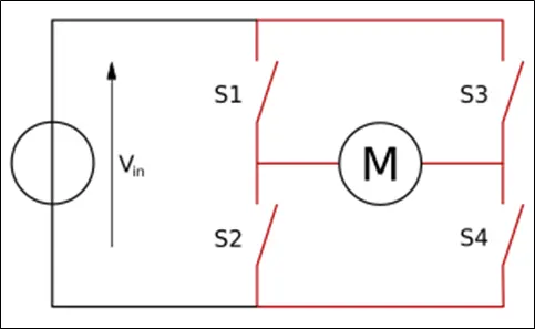
H-Bridge are available as integrated circuits,or can be built from discrete components.The term H-Bridge is derived from the typical graphical representation of such a circuit.An H -Bridge is built with four switches(solid-state or mechanical).When the switches S1 and S4 are closed , a possitive voltage will be applied accross the motor.By opening S1 and S4 switches and closing S2 and S3 switches,this voltages is reversed,allowing reverse operation of the motor.
Using the nomenclature above,the switches S1 and S2 should never be closed at the same time ,as this would cause a short circuit on the input voltage source.The same applied to the switches S3 and S4.This condition is known as 'SHOOT-THROUGH'
POWER H-BRIDGE MODEL:
PULSE WIDTH MODULATION:
- EXPLANATION:
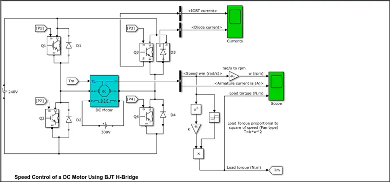
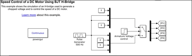
The Bipolar Junction Transistor (BJT) when used for power switching applications, operates as an IGBT. When it is conducting (BJT operating in the saturated region), a forward voltage Vf is developed between collector and emitter (in the range of 1 V). Therefore, the IGBT block can be used to model the BJT device.Saturated region is the region in which transistor tends to behave as a closed switch.The transistor has the effect of its collector and emitter being shorted.The collector and emitter currents are maximum in this mode of operation.The IGBT block does not simulate the gate current controlling the BJT or IGBT. The switch is controlled by a Simulink PWM model signal (1/0).
The DC motor uses the preset model (5 HP 24V 1750 rpm,Field:300V). It simulates a fan type load (where Load torque is proportional to square of speed). The armature mean voltage can be varied from 0 to 240 V when the duty cycle (specified in the Pulse Generator block) is varied from 0 to 100%.
The H-bridge consists of four BJT/Diode pairs (BJT simulated by IGBT models). Two transistors are switched simultaneously: Q1 and Q4 or Q2 and Q3. When Q1 and Q4 are fired, a positive voltage is applied to the motor and diodes D2-D3 operate as free-wheeling diodes when Q1 and Q4 are switched off. When Q2 and Q3 are fired, a negative voltage is applied to the motor and diodes D1-D4 operate as free-wheeling diodes when Q2 and Q3 are switched off.
A Flyback diode is also called as free-wheeling diode,here diode is to eliminate flyback when the abrupt voltage spike is witnessed across the inductive load when the supply current abruptly reduced.It helps the circuit from damaging.
Signum block (sign function) block is multiplied while calculating the load torque,if the motor speed is possitive i.e greater than 0,then output will multiplied with +1 and if the motor speed is negative i.e less than 0,then output multiplied by -1 and if motor speed is 0,output is multiplied by 0.
P1,P2,P3 and P4 blocks are from block which recieve input from the Goto block in PWM model.
When we run the default model with duty cycle 0.75,the results will as shown below
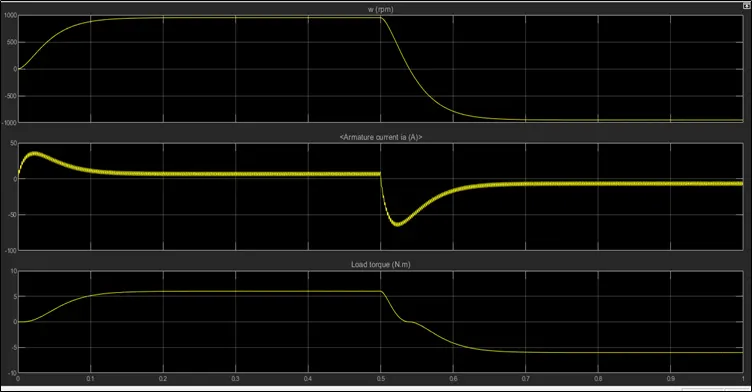
The motor starts in the positive direction with a duty cycle of 75% (mean DC voltage of 180V). At t= 0.5 sec., the armature voltage is suddenly reversed and the motor runs in the negative direction.'Scope' shows motor speed, armature current and load torque and 'Currents' shows currents flowing in BJT Q3 and diode D3.
How to modify the model such that armature current doesn't shootup when motor changes direction from froward to reverse???
PWM(Pulse width modulation) is one method that is often used for motor control using a microcontroller is pulse width modulation (PWM) method.The speed of the electric motor depends on the modulator voltage.The greater the voltage,the faster the rotation of an electric motor.
we know that,
`I =(V-E_b)/R_a` where I = armature current in A
V = Voltage in volts
Eb = Back EMF
Ra = armature resistance in ohms.
And also `E_b prop omega_m` where `omega_m` = speed of motor in rad/s
Since the armature resistance of the motor is very small,generally less then 1 ohm,therfore the starting current would be very large.As the speed of the motor increases the Back EMF value also increases and the (V-Eb) term goes on decreasing and the armature current decreases untill the motor attains its stable speed and to avoid the shoot up in the current duty cycle can be optimized.
By reducing the duty cycle the value of output voltage is decreased as `V_(op) = V_(bat)*d`,by keeping the battery voltage constant when duty cycle decreases the output voltage also decreases by which Armature current shoot up can be completely optimized.
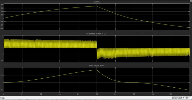
Result with duty cycle = 45%
- CONCLUSION:
Reducing the duty cycle will ultimately minimises the shoot up of armature current along with it will effects the load torque which is reduced from 6Nm to 2Nm and their will be fall in the speed of the motor also.
- FOUR QUADRANT CHOPPER :
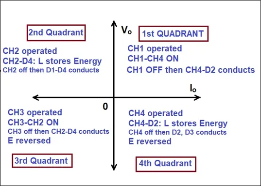
A four quadrant chopper is a chopper which can operate in all the four quadrants.The power can flow either from source to load or load to source in this chopper.In first-quadrant chopper acts as step-down chopper whereas in second quadrant it behaves as step-up chopper.
WORKING PRINCIPLE:
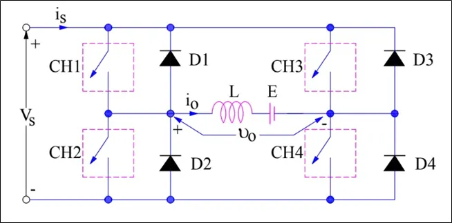
The circuit of a four quadrant chopper or class-E chopper basically consists of four semiconductor switches CH1 to CH4 and four diodes D1 to D4. The four diodes are connected in anti-parallel. The circuit diagram of this type of chopper is shown below.
FIRST QUADRANT:(FORWARD MOTORING)
For first quadrant operation, CH4 is kept ON, CH3 is kept OFF and CH1 is operated. When both CH1 & CH4 are ON simultaneously, the load gets directly connected to the source and hence the output voltage becomes equal to the source voltage. This essentially means that `v_0 =v_s`. It may be noted that the load current flows from source to load as shown by the direction of `i_0`.When CH1 is switched OFF, the load current free wheels through CH4 and D2. During this period, the load voltage and current remains positive.Thus, both the output voltage `v_s`and load current `i_0` are positive and hence, the operation of chopper is in first quadrant. It may be noted that, Class-E chopper operates as a step-down chopper in this case.
SECOND QUADRANT:(FORWARD BRAKING)
To obtain second quadrant operation, CH2 is operated while keeping the CH1, CH3 & CH4 OFF. When CH2 is ON, the DC source in the load drives current through CH2, D4, E and L. Inductor L stores energy during the On period of CH2.When CH2 is turned OFF, current is fed back to the source through D1, D4. It should be noted at this point that (E+Ldi/dt) is more than the source voltage `V_s`. As load voltage `V_0` is positive and `I_0` is negative, it is second quadrant operation of chopper. Since, the current is fed back to the source, this simply means that load is transferring power to the source. For second quadrant operation, load must contain emf E as shown in the circuit diagram. In second quadrant, configuration operates as a step-up chopper.
THIRD QUADRANT:(REVERSE MOTORING)
For third quadrant operation, CH1 is kept off, CH2 is kept ON and CH3 is operated. When CH3 is ON, load gets connected to source and hence load voltage is equal to source voltage. But carefully observe that the polarity of load voltage `V_0` is opposite to what shown in the circuit diagram. Hence, `V_0` is assumed negative. Let us now see what is the status of load current `i_0`. It may be seen that io is flowing in the direction opposite to shown in the circuit diagram and hence negative.Now, when CH3 is turned OFF, the negative load current free wheels through the CH2 and D4. In this manner, vo and io both are negative. Hence, the chopper operates in third quadrant.
FOURTH QUADRANT:(REVERSE BRAKING)
When CH4 is turned ON, positive current flows through CH4, D2, L and E. Inductance L stores energy during the time CH4 is ON. When CH4 is made OFF, current is fed back to the source through diodes D2, D3. Here load voltage is negative but the load current is always positive. This leads to chopper operation in fourth quadrant. Here, power is fed back to the source from load and chopper acts as a step-up chopper.
FOUR QUADRANT CHOPPER DC-DRIVE(DC7) MODEL:
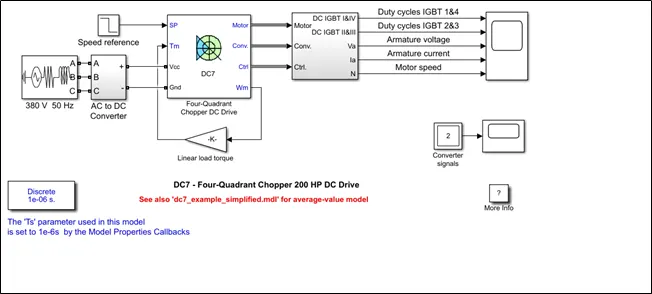
The 200 HP DC motor is separately excited with a constant 150 V DC field voltage source. The armature voltage is provided by an IGBT converter controlled by two PI regulators. The converter is fed by a 515 V DC bus obtained by rectification of a 380 V AC 50 Hz voltage source. In order to limit the DC bus voltage during dynamic braking mode, a braking chopper has been added between the diode rectifier and the DC7 block.The first regulator is a speed regulator, followed by a current regulator. The speed regulator outputs the armature current reference used by the current controller in order to obtain the electromagnetic torque needed to reach the desired speed. The speed reference change rate follows acceleration and deceleration ramps in order to avoid sudden reference changes that could cause armature over-current and destabilize the system.The current regulator controls the armature current by computing the appropriate duty ratios of the 5 kHz pulses of the four IGBT devices (Pulse Width Modulation). For proper system behaviour, the instantaneous pulse values of IGBT devices 1 and 4 are opposite to those of IGBT devices 2 and 3. This generates the average armature voltage needed to obtain the desired armature current. In order to limit the amplitude of the current oscillations, a smoothing inductance is placed in series with the armature circuit.
The Four-Quadrant Chopper DC Drive (DC7) block represents a four-quadrant, DC-supplied, chopper (or DC-DC PWM converter) drive for DC motors. This drive features closed-loop speed control with four-quadrant operation. The speed control loop outputs the reference armature current of the machine. Using a PI current controller, the chopper duty cycle corresponding to the commanded armature current is derived. This duty cycle is then compared with a sawtooth carrier signal to obtain the required PWM signals for the chopper.
RESULTS:
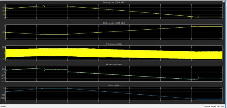
- Before starting the simulation, set the initial bus voltage to 515 V via the GUI block ('Initial States Setting' button and 'Cbus' variable).
- Start the simulation. You can observe the motor armature voltage and current, the four IGBT pulses and the motor speed on the scope. The current and speed references are also shown.
- The motor is coupled to a linear load, which means that the mechanical torque of the load is proportional to the speed.
- The speed reference is set at 500 rpm at t = 0 s. Observe that the motor speed follows the reference ramp accurately (+400 rpm/s) and reaches steady state around t = 1.3 s.
- The armature current follows the current reference very well, with fast response time and small ripples. Notice that the current ripple frequency is 5 kHz.
- At t = 2 s, speed reference drops to -1184 rpm. The current reference decreases to reduce the electromagnetic torque and causes the motor to decelerate with the help of the load torque.
- At t = 2.2 s, the current reverses in order to produce a braking electromagnetic torque (dynamic braking mode). This causes the DC bus voltage to increase.
- At t = 3.25 s, the motor reaches 0 rpm and the load torque reverses and becomes negative. The negative current now produces an accelerating electromagnetic torque to allow the motor to follow the negative speed ramp (-400 rpm/s). At t = 6.3 s, the speed reaches -1184 rpm and stabilizes around its reference.
COMPARISON OF 4 QUADRANT CHOPPER WITH H-BRIDGE:
- Four quadrant chopper can operates in all four modes(Forward motoring,Forward braking,Reverse motoring,Reverse braking),but H-bridge can operate only in two modes(Forward and Reverse).
- In four quadrant chopper Regenerative braking is possible,but H-bridge Regenaritive Braking is not possible.
- Due to the use of high switching frequency DC-DC converters, a lower armature current ripple is obtained in four quadrant chopper when compared to H-bridge.
- MODELING EV USING DC7 BLOCK:
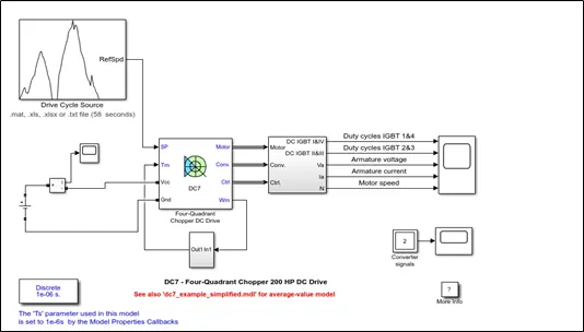
To model EV using DC7 block following modification are made,
- Use a simple DC source as a energy source and provide appropriate voltage value for an EV.
- Give any driving cycle input by replacing the step signal otherwise create the drive cycle using excel file and import the data to same.
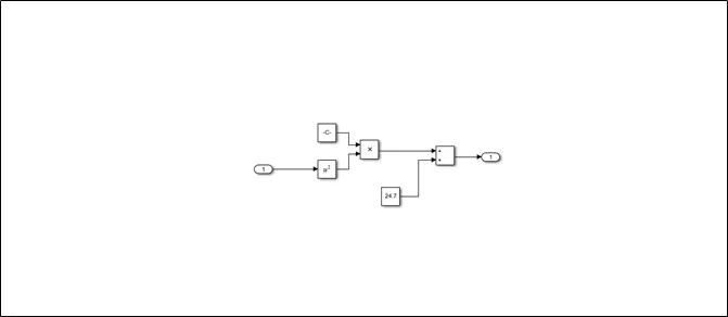
- Linear load torque block is replaced with a subsystem model according to the load characterstics given by `T_(TR) = 24.7+0.0051*omega^2`
- Change the simulation time with respect to the drive cycle data.
- The duty cycle switches can be kept as default.
MODIFIED DC7 BLOCK:
SUBSYSTEM OF LOAD TORQUE CHARACTERSTICS:
DRIVE CYCLE:
https://docs.google.com/spreadsheets/d/1xa8cys2UsOIZHJTTGea310RZhX0PNUiw4MeWQmpKFhE/edit?usp=sharing
- RESULT:
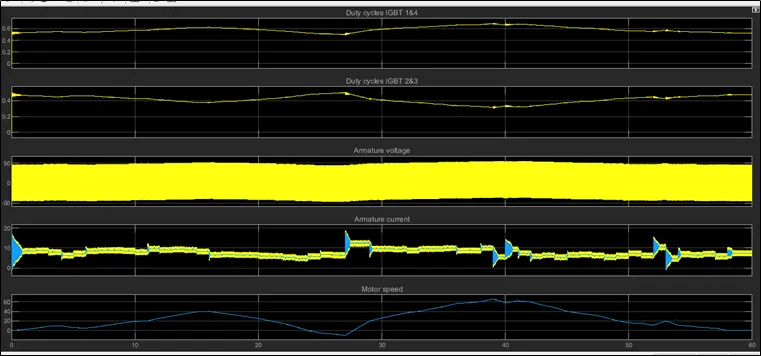
- Duty cycle IGBT 1 and 4,IGBT 2 and 3 are complimentry in nature.
- Armature voltage(72V) is sufficient to drive the EV in given Drive cycle.
- Armature current also follows the reference current very well with fast response time and small ripple.
- Motor speed also follows the reference drive cycle very well.