Week 7 Challenge - Assembly Workbench
Assembly workbench in Catia V-5 is one in which a previously created 3D models are brought together and joined using different constraints as per the master section. This is the last process that is carried out on a model before sending it further on the product development stage. It is done by selecting new file and then product.
-> Steps involved in assembling Model 1
*) The sketch was created as per the sketch provided. It was considered that the sketch was iso-constraint.
*) In the same manner, all the other sketches were drawn.
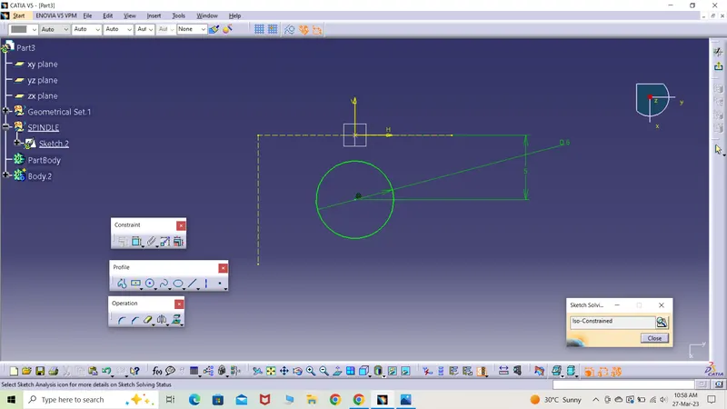
*) The sketch was padded and converted into a 3D model. The dimension of the model was set according to the given drawing.
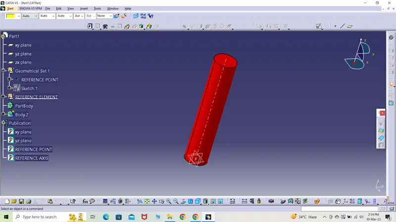
*) In the same manner all the other parts were created and the s.s. is attached below.
*) All the below parts are shown in isometric view.
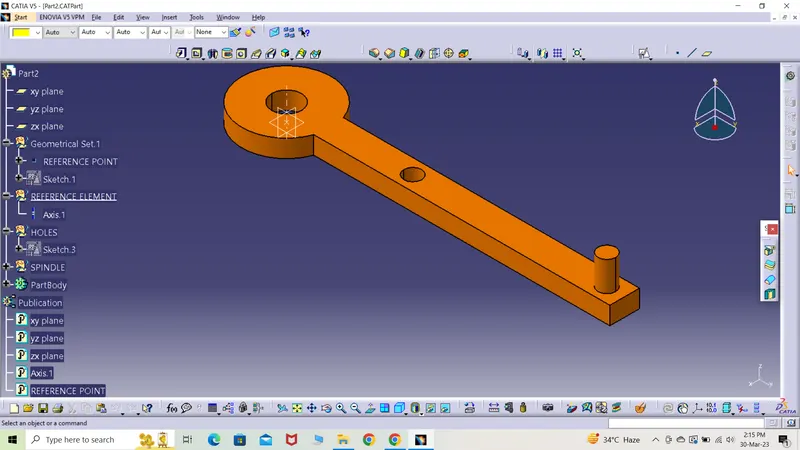
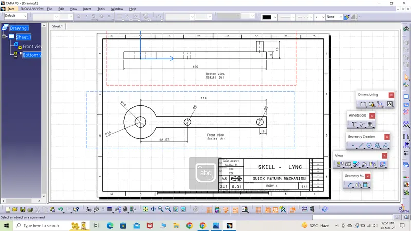
*) All the parts are created as a new part and named using numerals.
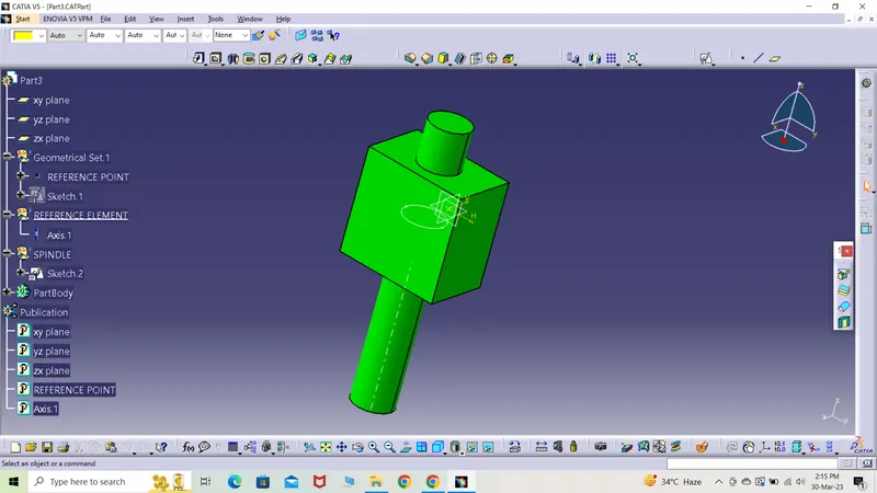
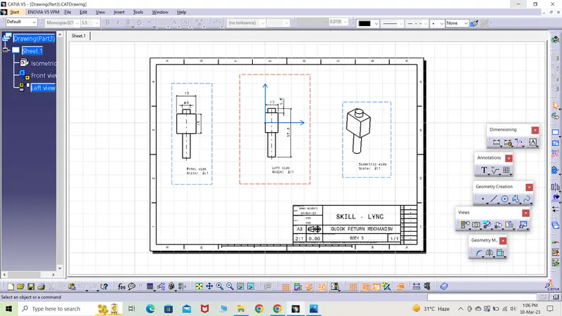
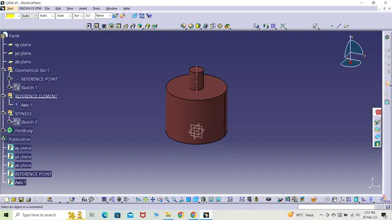
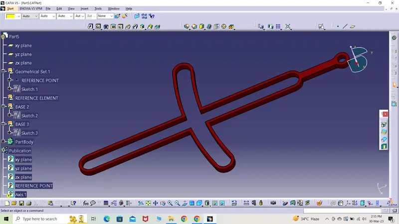
*) All the parts were opened in an assembly to create a product.
*) The main heading file was renamed to quick return mechanism.
*) A separate part file was created by the name 'skeleton' and was rearranged by using 'graph tree reordering' option
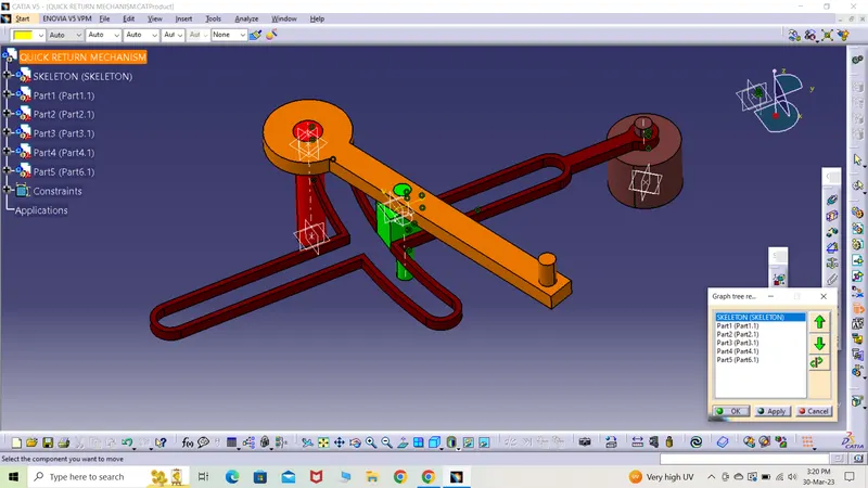
*) All the parts were colored distinctively to clearily observe the change in position at the time of assembly.
*) All the part files were renamed with 'reference point' and reference element under which axis was created by the name 'reference axis'.
*) All the coordinate planes and reference point and axis were published by going to 'tools' and selecting 'publication'.
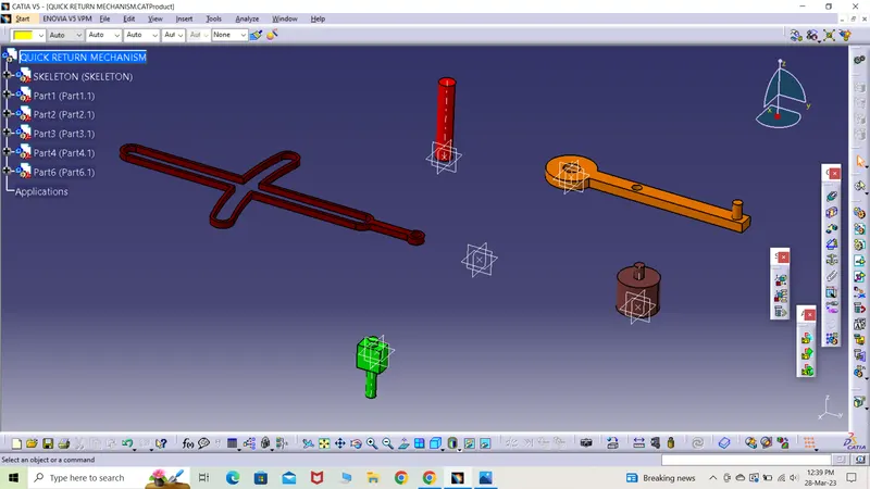
*) By using 'explode' option, all the parts were arranged randomly and away from each other.
*) By using constraint toolbar, coincidence constraint was used and later two part along with axis or point were selected to move the part as per the sketch provided.
*) A separate file by Catia is maintained to keep record of all the constraints in between two particular parts.
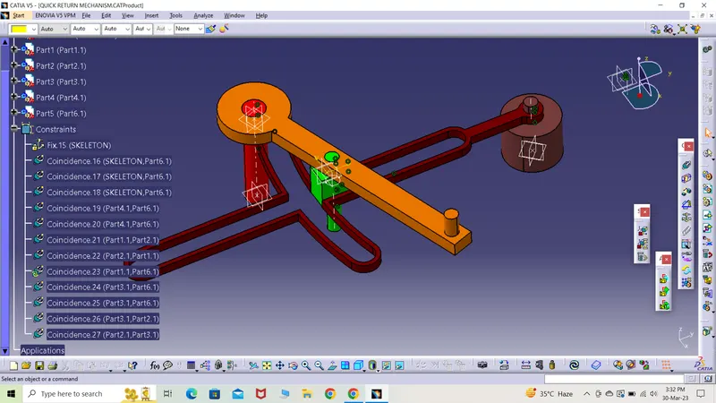
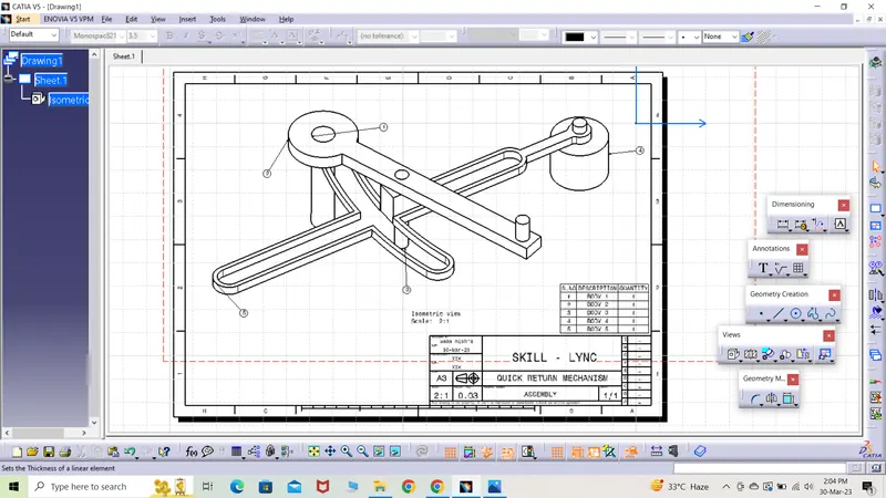
*) One by one all the parts are assembled and the s.s. is attached below.
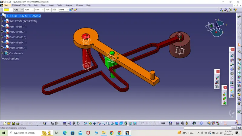
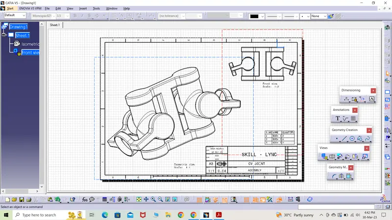
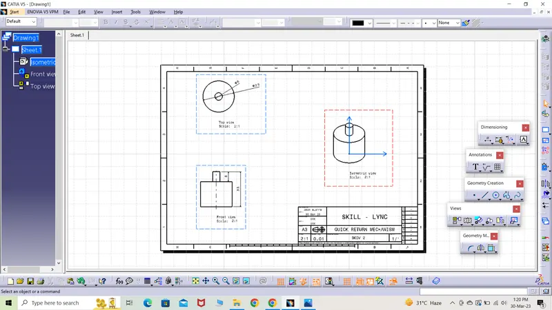
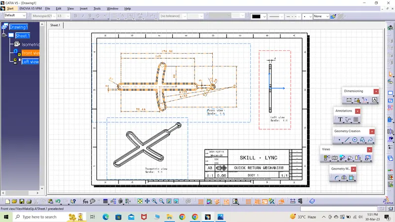
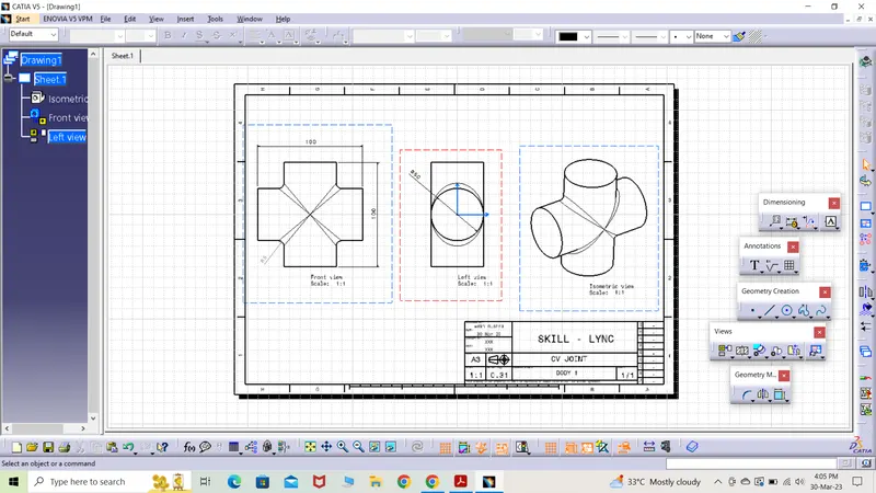
*) The models were drafted and saved both in extension .Catdrawing and .pdf format.
-> Model 2 assembly
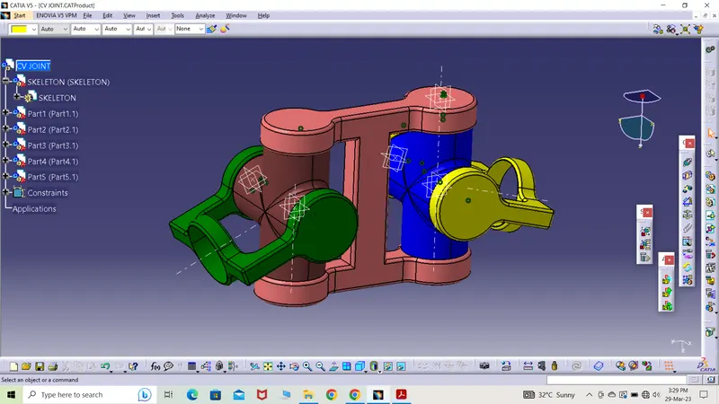
*) The same aforementioned method is used to create and assemble the parts to create CV joint.
*) It is known to us that a CV joint comprises of a spider, centre yoke and driven and driving yoke.
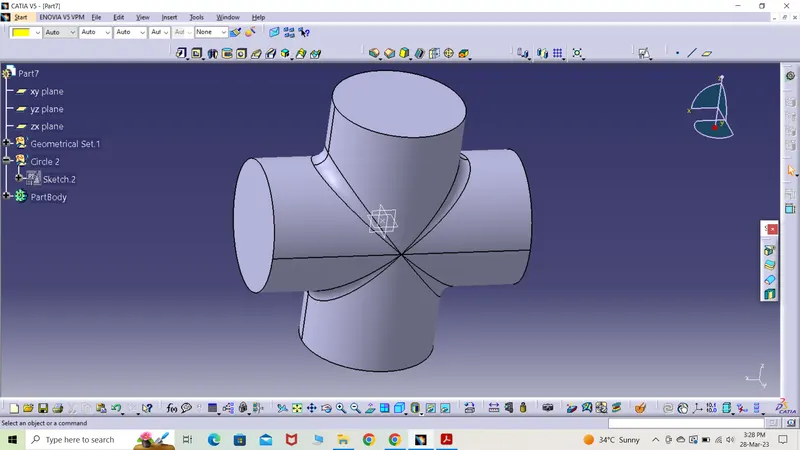
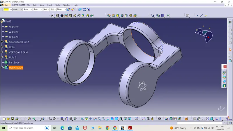
*) In this model, there are two sets of a part that are spider and yoke.
*) To save time and effort, these two particular parts were just copied to create two new parts.
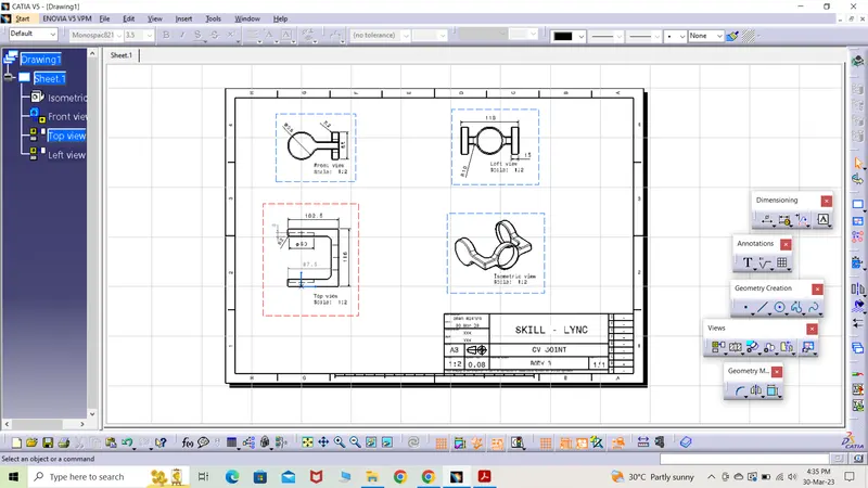
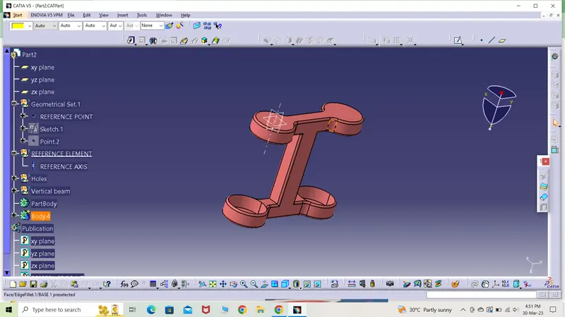
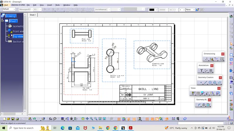
*) The assembly is shown below.