Week 7 Challenge - Assembly Workbench
Objective;
To create assemblies of Quick return mechanism and CV joint and to also create a 2D drawing of the given assemblies’ components.
Introduction;
Assembly Workbench in CATIA is a tool used for creating and managing assemblies of 3D models. It allows users to assemble various parts and components into a single product and simulate the assembly to check for fit, interference, and other design considerations. Assembly Workbench provides tools for managing assembly constraints, such as mating and aligning components, as well as tools for analyzing the assembly and its components. In CATIA, Assembly Workbench is an essential tool for creating complex mechanical products or systems.
Procedure To Create These Bodies and Assemble Them;
To create the Quick Return Mechanism & the CV Joint, we need to assemble their respective individual parts. The 2D drawings provided in the challenge can be used to create these parts. Once the parts are created, they can be assembled to form complete bodies. This process involves carefully following the assembly instructions and ensuring that each part is correctly positioned and secured. As a professional, it is important to communicate clearly and concisely to colleagues or team members about the steps involved in the assembly process and to ensure that everyone understands the requirements and expectations for the project but since currently I am doing this entire p In CATIA's Assembly Workbench, the creation of a reference point, known as the Skeleton Reference, is a crucial step in designing an assembly. This point serves as the origin for assembling the various parts of it. To ensure the proper positioning of parts, a reference point must also be created for each component.
To establish the Skeleton Reference, the 'Fix Component' command in the Constraint Toolbar is employed. This command allows for the anchoring of the Skeleton Reference point to a specific location. Once established, the individual parts can be connected to the Skeleton Reference point using the 'Constraint Toolbar' in the Assembly Workbench.
The Coincidence Constraint tool is a commonly used command in the Constraint Toolbar, which is employed to link the reference points of each part to the Skeleton Reference point. This ensures that the parts are assembled in the correct orientation and position as required by the design.
In summary, creating a Skeleton Reference point and employing the Coincidence Constraint tool to connect individual parts to it is a critical process in CATIA's Assembly Workbench. The proper use of these tools ensures the accurate modeling, testing, and analysis of assemblies, resulting in a final product that meets the desired specifications.
Various points and axes are made for each body so that it can be assembled concerning the skeleton reference point process on my own hence I have to consider all these things.
Quick Return Mechanism Part 1 (Oscillating Arm);
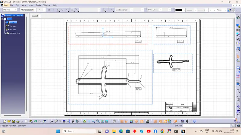
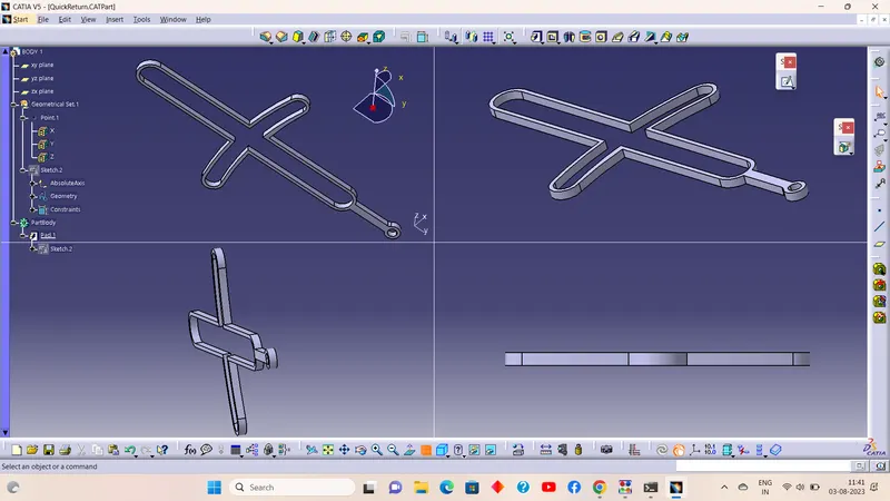
Quick Return Mechanism Part 2 (Pivot);
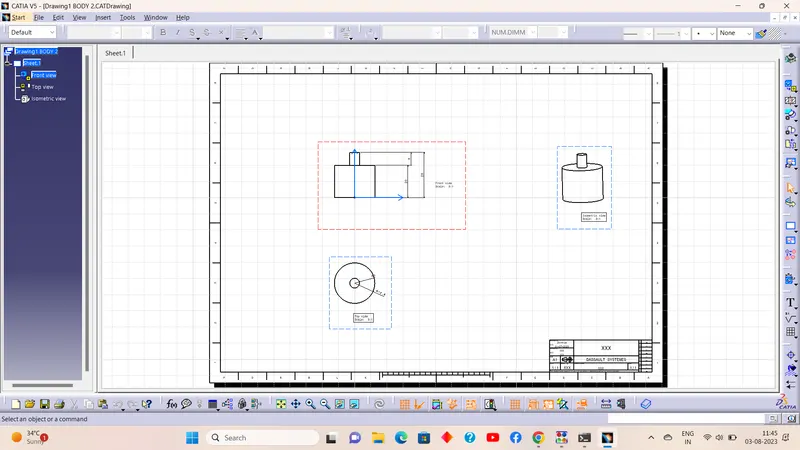
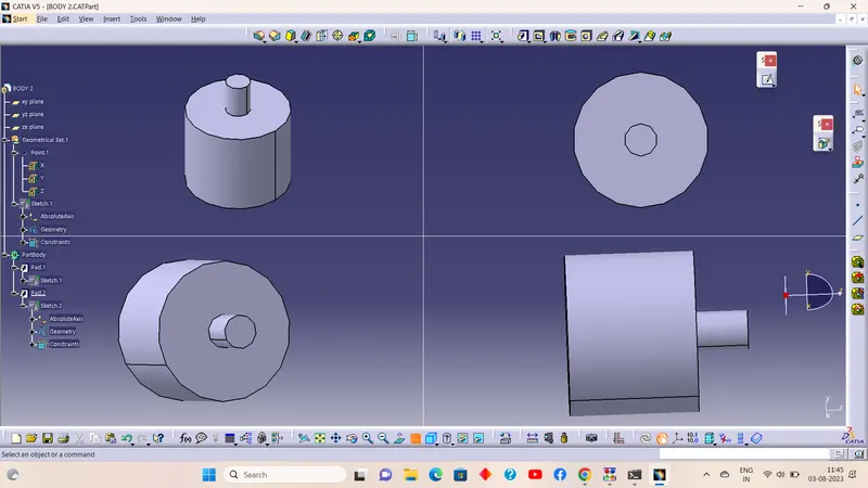
Quick Return Mechanism Part 3 (Oscillating Pin);
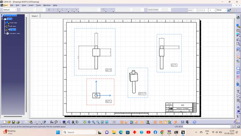
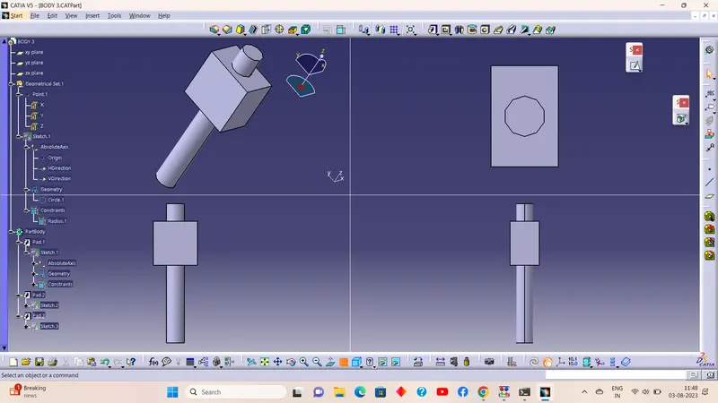
Quick Return Mechanism Part 4 (Rotating Arm);
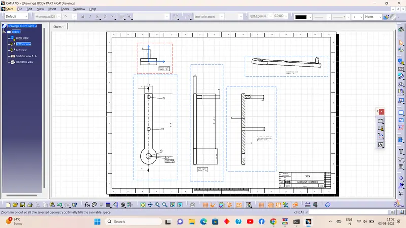
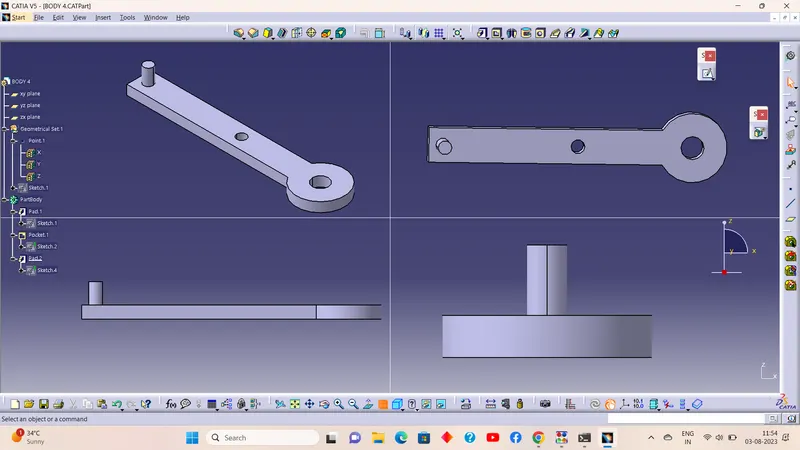
Quick Return Mechanism Part 5 (Pin);
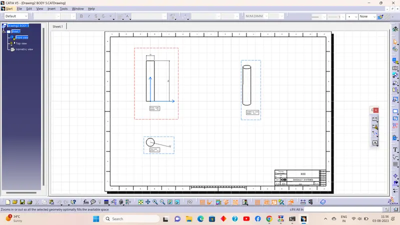
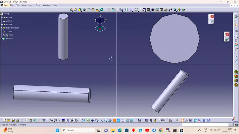
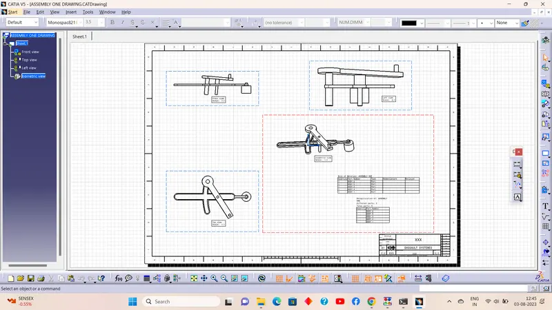
a) QUICK RETURN MECHANISM:
A quick return mechanism is an apparatus to produce a reciprocating motion in which the time taken for travel in the return stroke is less than in the forward stroke. It is driven by a circular motion source (typically a motor of some sort) and uses a system of links with three turning pairs and a sliding pair.
There are three types of quick return mechanism
- Hydraulic drive
- Crank and slotted link mechanism
- Whitworth mechanism
A quick return mechanism is a mechanism that produces a reciprocal effect so that the system takes less time in the return stroke when compared with the forward stroke. In the quick-return mechanism, a circular movement like the crank and lever mechanism is converted into reciprocal movement but the return time is different from the forward moment. In several applications, this process is used. Some of them are shapers, slotters, screw-press, mechanical drives, etc. The time required for cutting is reduced with the assistance of a quick return mechanism.
Views of the Assembly;
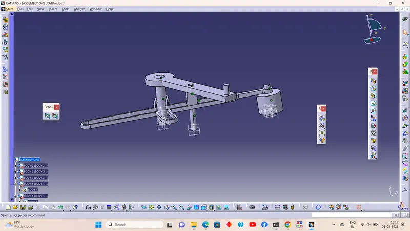
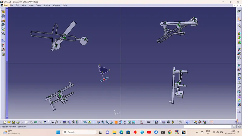
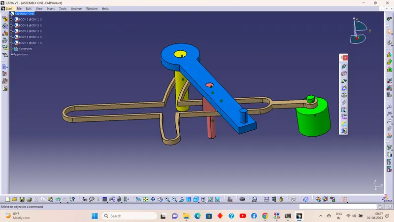
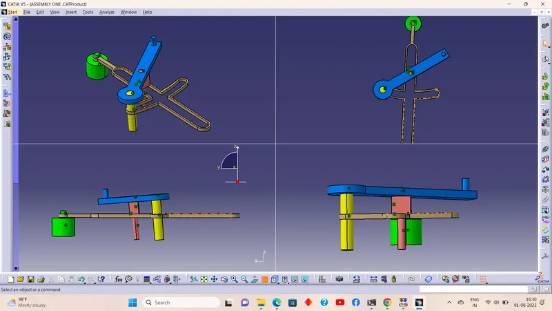
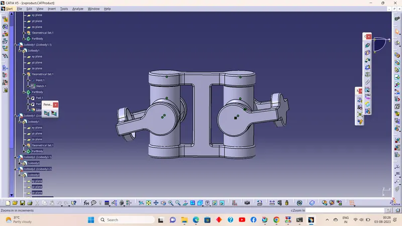
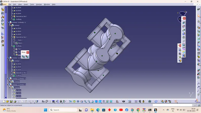
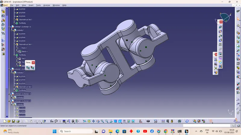
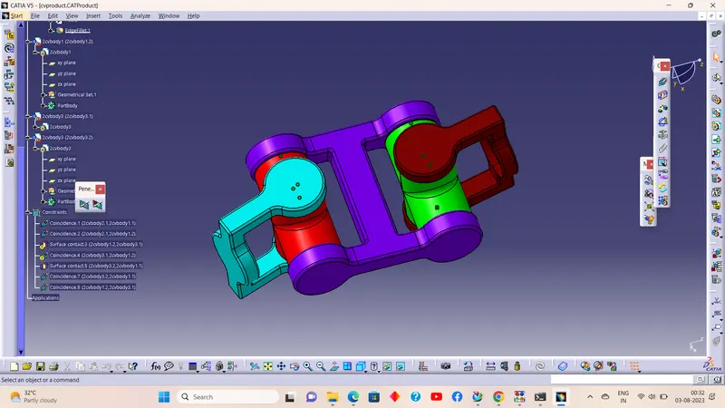
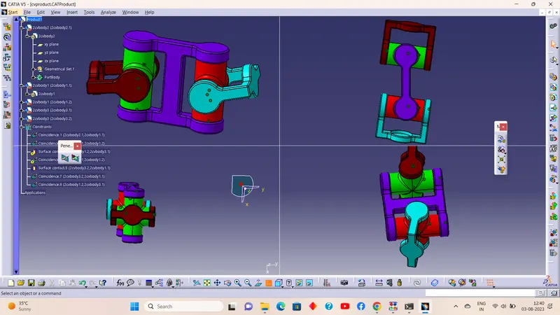
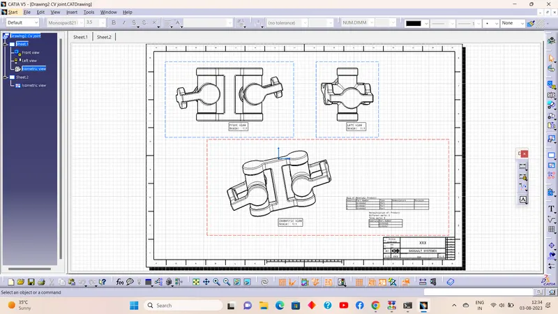
b) CV JOINT:
Constant-velocity joints (also known as homokinetic or CV joints) allow a drive shaft to transmit power through a variable angle, at constant rotational speed, without an appreciable increase in friction or play. They are mainly used in front-wheel drive vehicles. Modern rear-wheel drive cars with independent rear suspension typically use CV joints at the ends of the rear axle half shafts and increasingly use them on the drive shaft.
All front-wheel drive cars have Constant Velocity joints or CV joints on both ends of the drive shafts (half shafts). Inner CV joints connect the drive shafts to the transmission, while the outer CV joints connect the drive shafts to the wheels. Many rear-wheel drive and four-wheel drive cars as well as trucks also have CV joints.
The CV joints are needed to transfer the torque from the transmission to the drive wheels at a constant speed while accommodating the up-and-down motion of the suspension. In front-wheel drive cars, CV joints deliver the torque to the front wheels during turns. There are two most commonly used types of CV joints: a ball-type and a tripod-type. In front-wheel drive cars, ball-type CV joints are used on the outer side of the drive shafts (outer CV joints), while the tripod-type CV joints are mostly used on the inner side (inner CV joints).
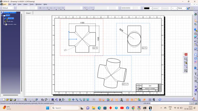
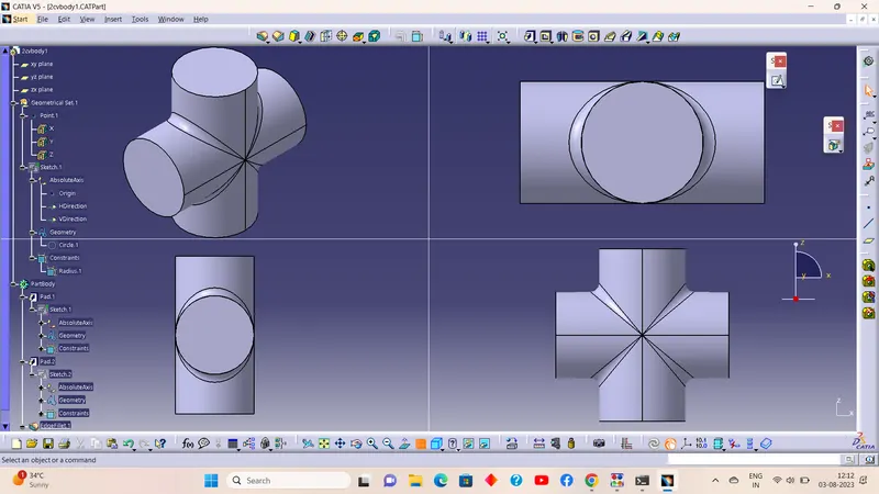
Cv-Joint Part 1 (Cross Journal);
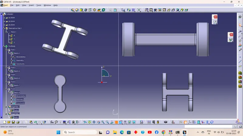
Cv-Joint Part 2 (Central H Yoke);
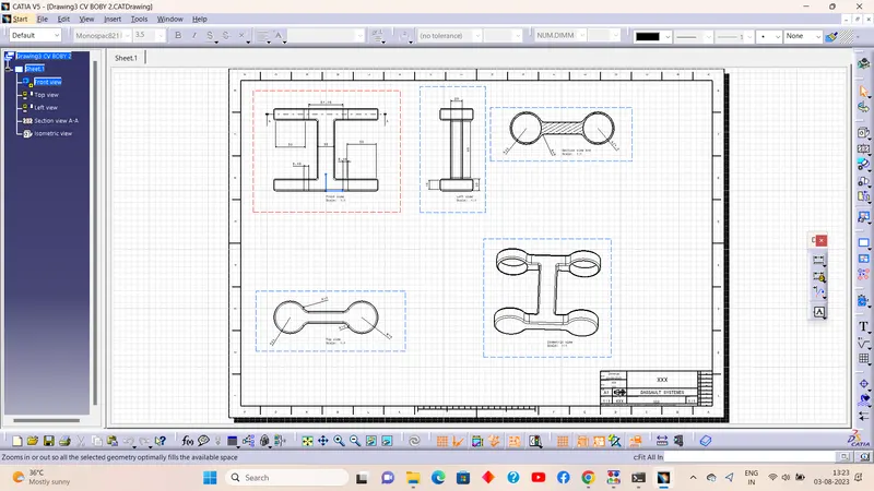
Cv-Joint Part 3 (Yoke);
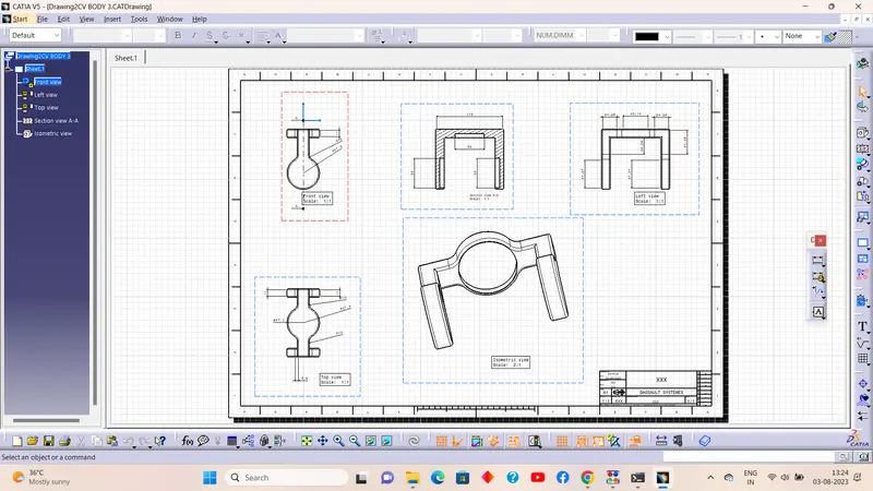
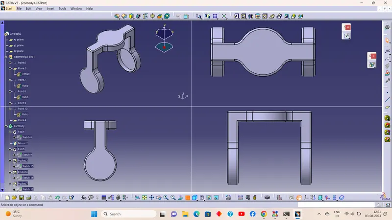
Views of the Assembly;