Week 7 Challenge - Assembly Workbench
Objective:
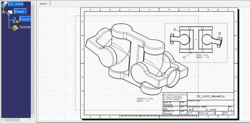
In this week's assignment, I want to create the 3D solid parts which was given in the link and then assemble them in the assembly workbench and then I want to draft these parts and the assembly in the draft workbench.
Here we are having two assemblies: 1. Quick Return Mechanism
2. CV- Joint
1] QUICK RETURN MECHANISM
A quick return mechanism is an apparatus to produce a reciprocating motion in which the time taken for travel in return stroke is less than in the forward stroke. It is driven by a circular motion source (typically a motor of some sort) and uses a system of links with three turning pairs and a sliding pair. A quick-return mechanism is a subclass of a slider-crank linkage, with an offset crank.
Quick return is a common feature of tools in which the action is performed in only one direction of the stroke, such as shapers and powered saws because it allows less time to be spent on returning the tool to its initial position.
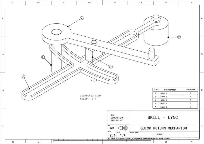
In this mechanism we are having the five parts.
QRM_Path :
First I decided to create the path for it by using the diagram.
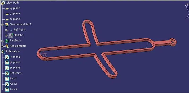
In the catpart file we will create this solid part which was shown below,
And then I created this part drawing in the draft workbench,
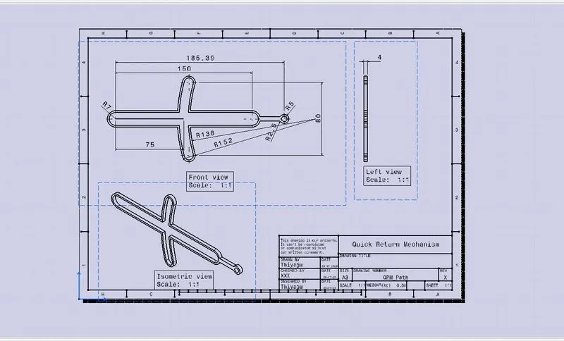
And I follow the same process for all other parts in the quick return mechanism.
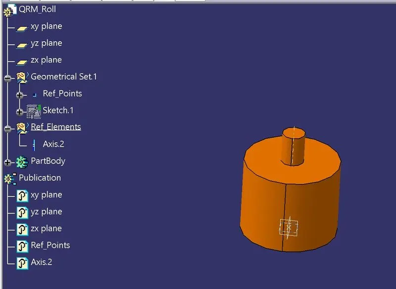
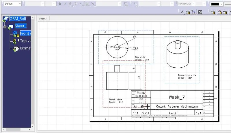
QRM_Roll:
QRM_Shaft :
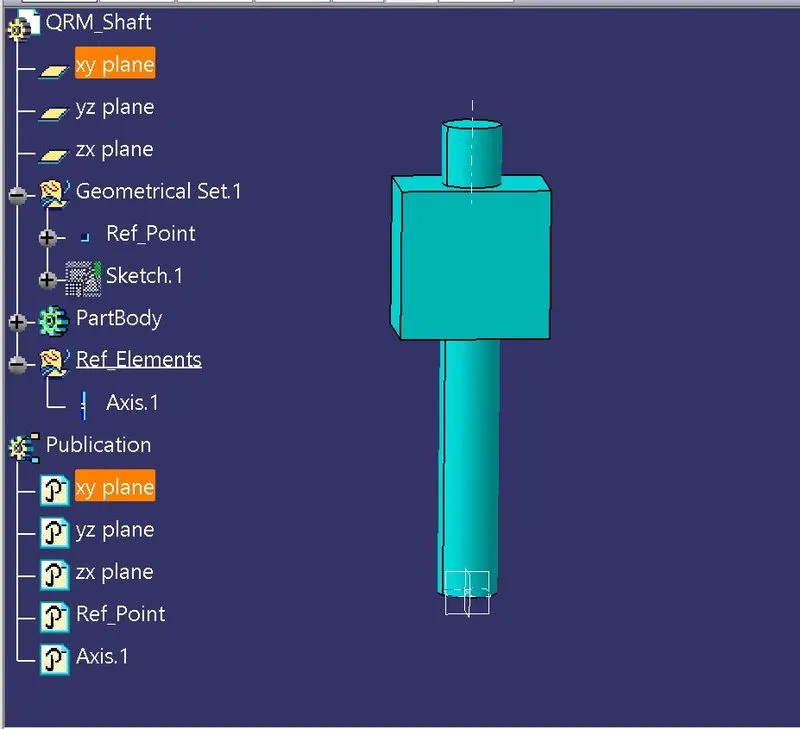
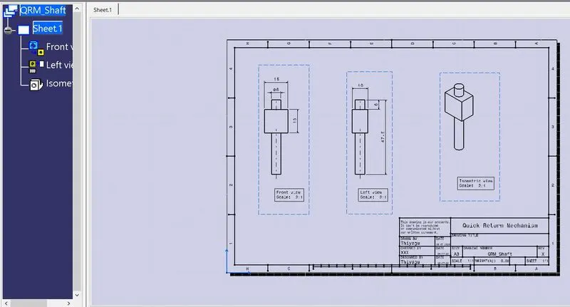
QRM_Handle :
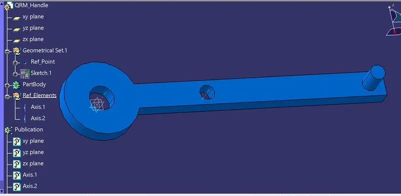
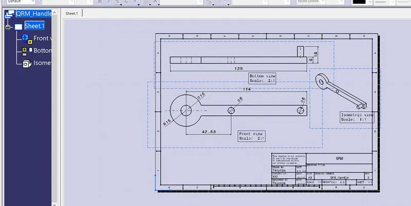
QRM_Rod :
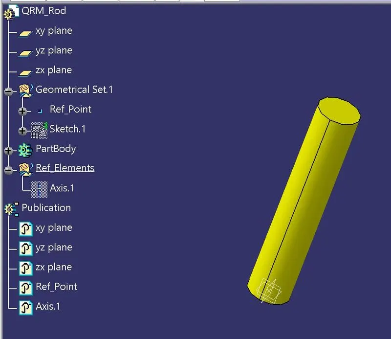
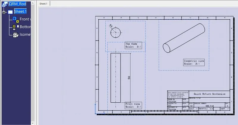
So, Finally we are created all the parts needed to create the assembly of quick return mechanism. Then we'll start to assemble them in the assembly workbench.
QUICK RETURN MECHANISM - ASSEMBLY :
Before starting the assembly process we want to create a new product file in the CATIA. And then add all the required parts in the product file. After adding them in this product, all the required part files are inside the assembly product file.
While starting the assembly first we want to constraint fix for any one of the part file in the assembly file. So I decided to create a new part file named as Skeleton added under the main assembly tree.
In this Skeleton part file it only has the planes and the origin point in its structure. And then I decided to publish it.
The publication is used for while we update any one of the part file constraints, all the other part files which is related with that constraints will get updated.
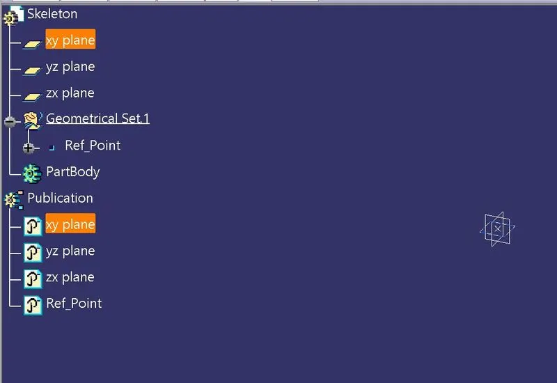
In the skeleton part file it only has the planes and the origin point.
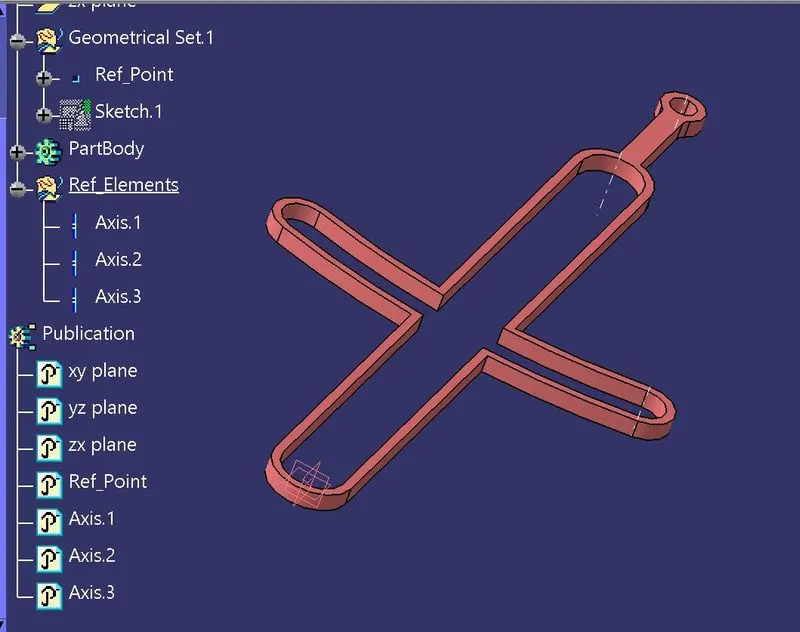
The above diagram shows the QRM_Path, its origin point and the axis on the circular faces are created and published. Because it will used for the assembly relations with other coincidence and concentric relations with the other parts.
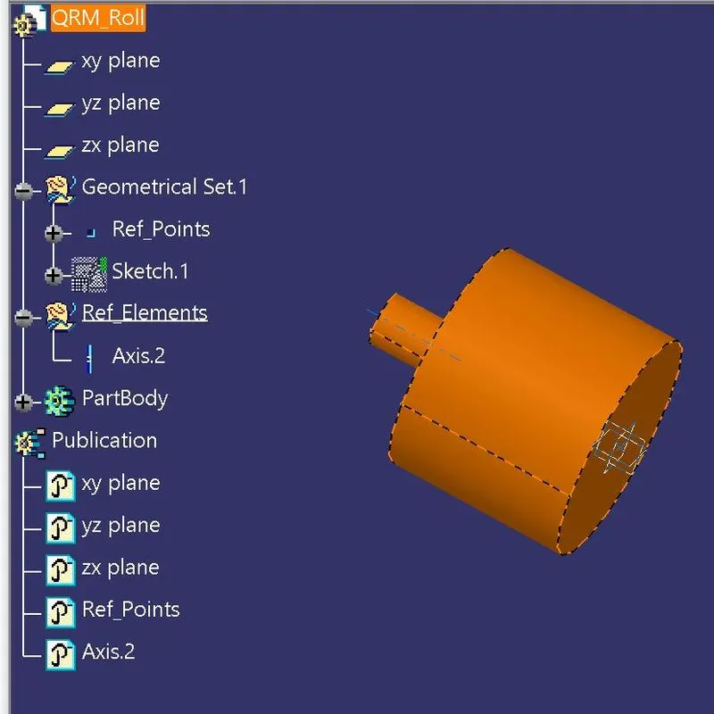
In the above QRM_Roll part file published it palnes and its origin point and also the axis reference.
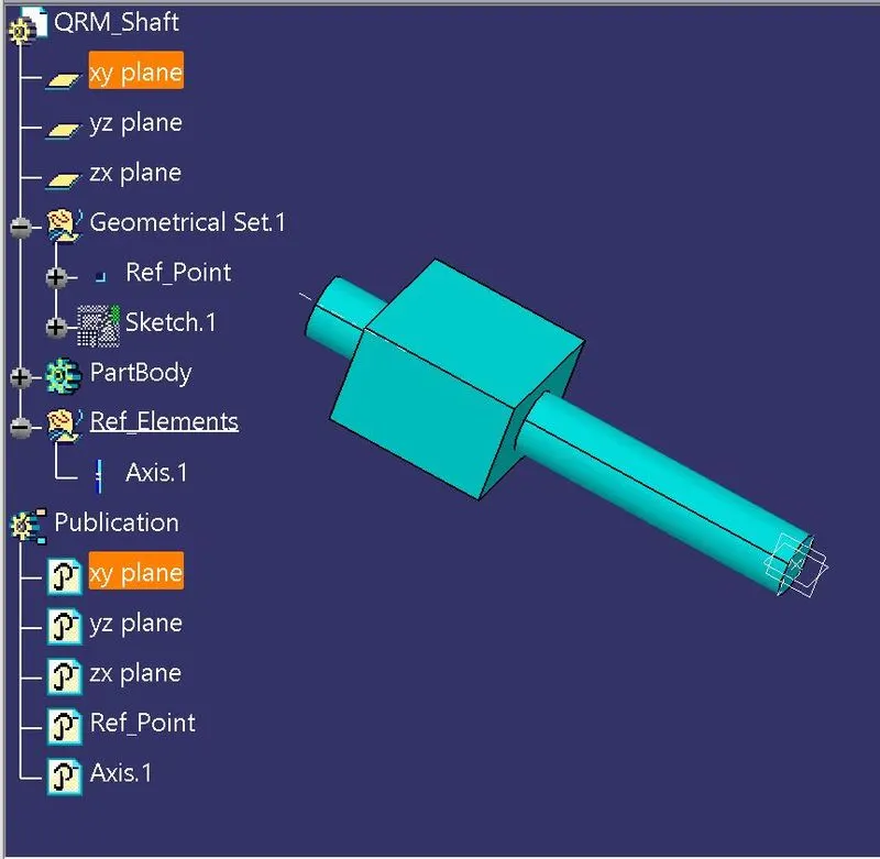
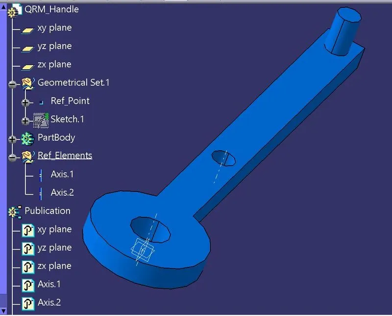
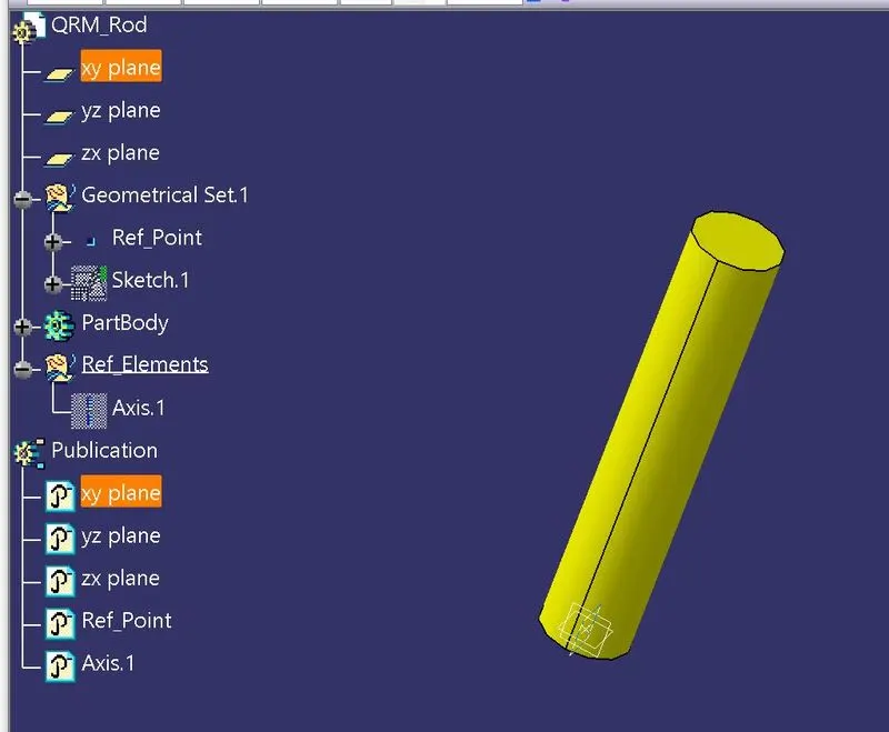
And then for all the required points and axis are created and published in the part file. The axis for all the parts are created under the Geometry named as Ref "Elements".
QRM - ASSEMBLY PROCESS:
First the skeleton part is fixed by using the Fix tool in the constraints toolbar.
Then the QRM_Path part is coincident with the same reference point by using the coincidence tool in the constraints tool.
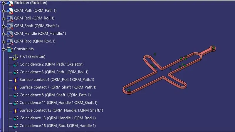
And the QRM_Roll is added with the QRM_Path by using the coincidence tool to coinside with the axis on the required position and then the surface are contacted by using the Contact constraint.
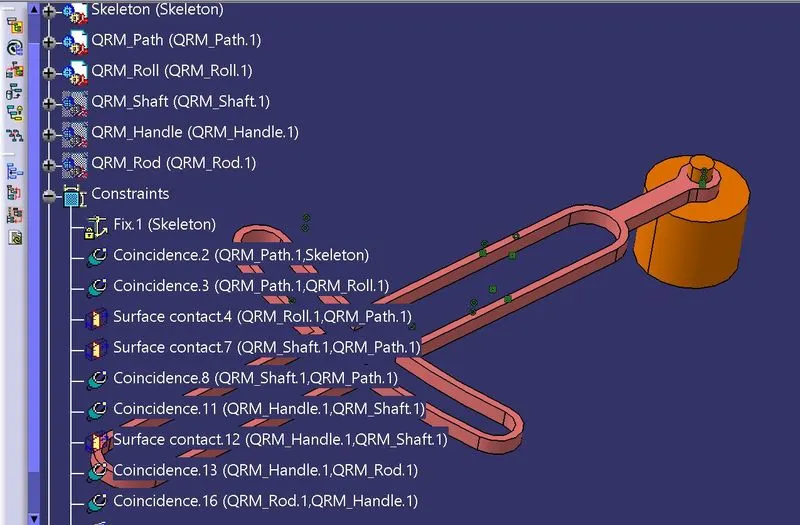
Then the QRM_Shaft is placed in the middle of the path by using the surface contact.
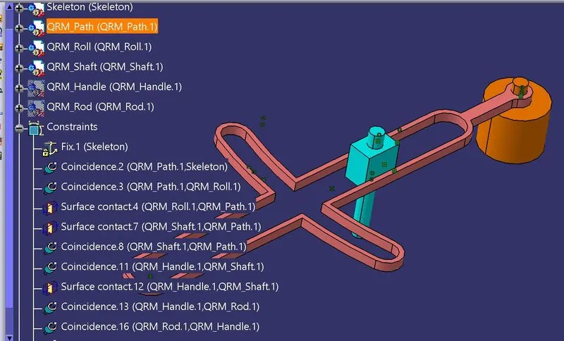
The QRM_Handle is placed on the position and contact with the shaft and rod. First I want to coincide with the shaft by using the coincidence tool and then made the surface contact with them.
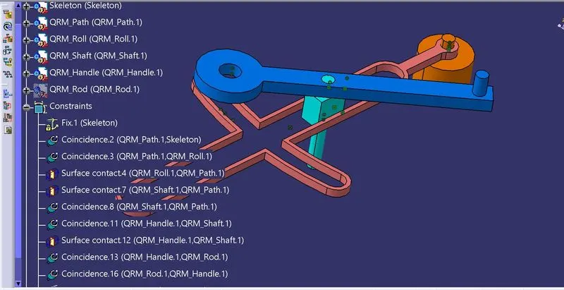
Finally I added the QRM_Rod on the required position, First made the coincidence of the axis with the rod and the shaft. Then I made the line contact with the rod and the path. 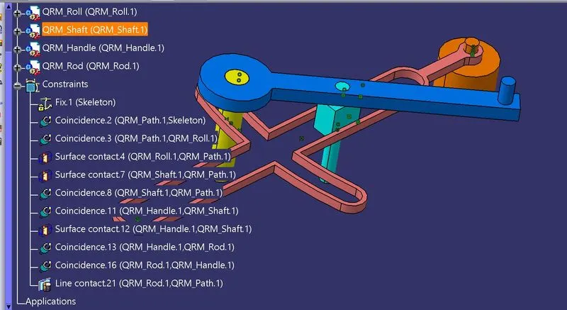
Finally the assembly is done for the quick return mechanism which was shown below in the variious views.
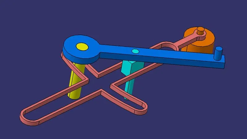
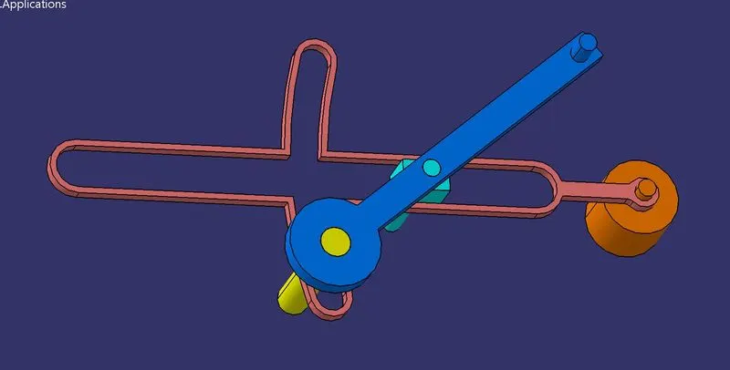
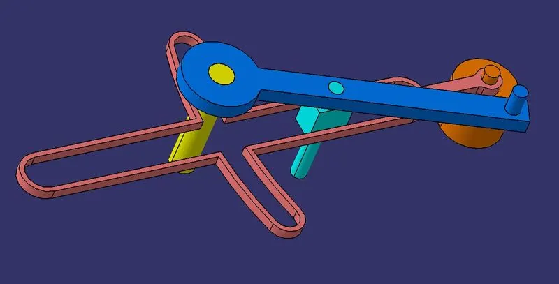
And then I created the assembly drawing for this assembly in the drafting workbench.
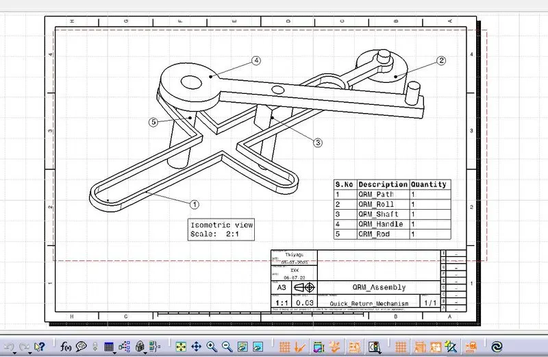
2] CV-JOINT :
A constant-velocity joint (also called a CV joint) is a mechanical coupling which allows the shafts to rotate freely (without an appreciable increase in friction or backlash) as the angle between the two shafts moves within a certain range.
A common use of CV joints is in front-wheel drive vehicles, where they are used to transfer the engine's power to the wheels, even as the angle of the driveshaft varies due to the operation of the suspension.
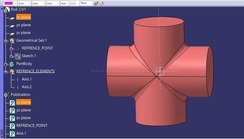
In this assembly of CV joint we are having three parts on its assembly. First we want to create that parts in the part file in the CATIA workbench. Then we want to publish required geometry parameters for made the connection in the assembly workbench.
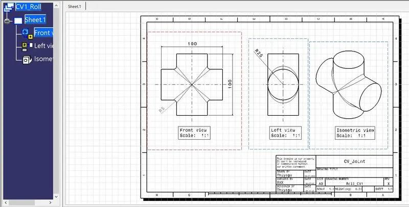
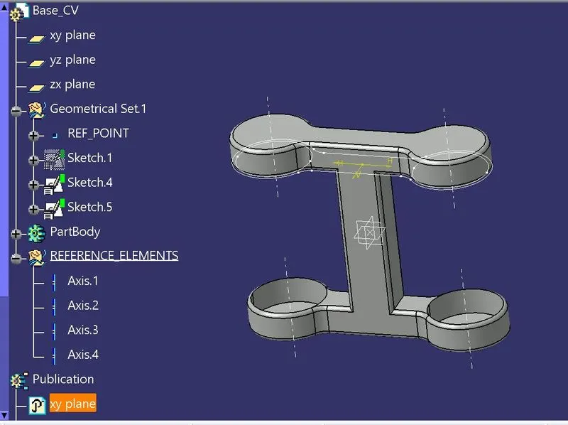
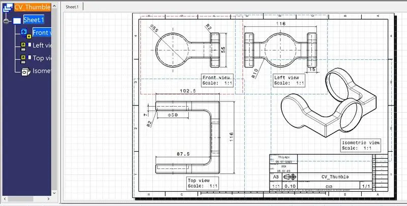
The three parts are created and then assigned into the assembly workbench. Before enter into the assembly the drafting work is done for these three parts which was shown below.
CV_Roll :
CV_Base:
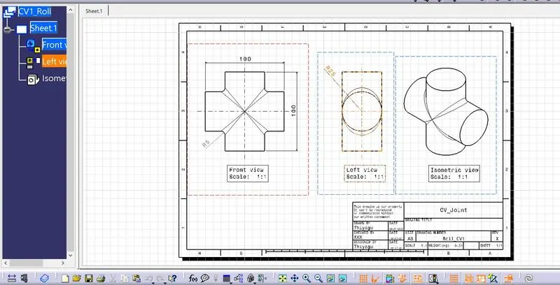
CV_Thumble:
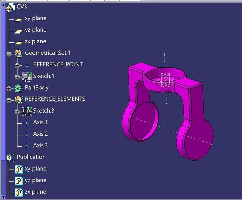
CV_JOINT - ASSEMBLY :
For assembly we want to create the product file and then add the part files required for this. And we already published the required the axis and points in the publication. Then we'll start the assembly process for CV_Joint.
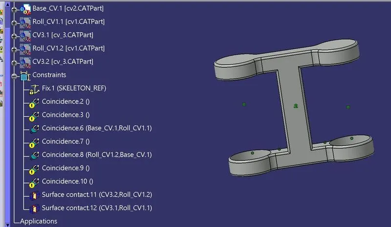
First I decided to create one origin point and planes on the Skeleton part file and then added that in the assembly product file. And make the origin point with Fix constraints.
And then added the CV_Base on the assembly workbench and make its origin point coincidence with the skeleton origin point by using the Coincidence constraint.
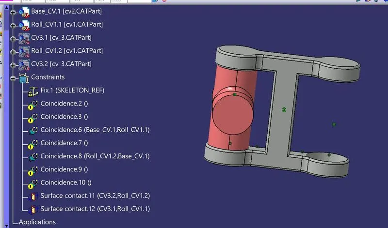
Then I added the CV_Roll part coincidence with the CV_Base on one side using the axis. And then made the Contact constraint to place it on the required position.
For making the opposite side for another one CV_Roll, I'm using the same procedure to make that by adding the another one CV_Roll in the product file.
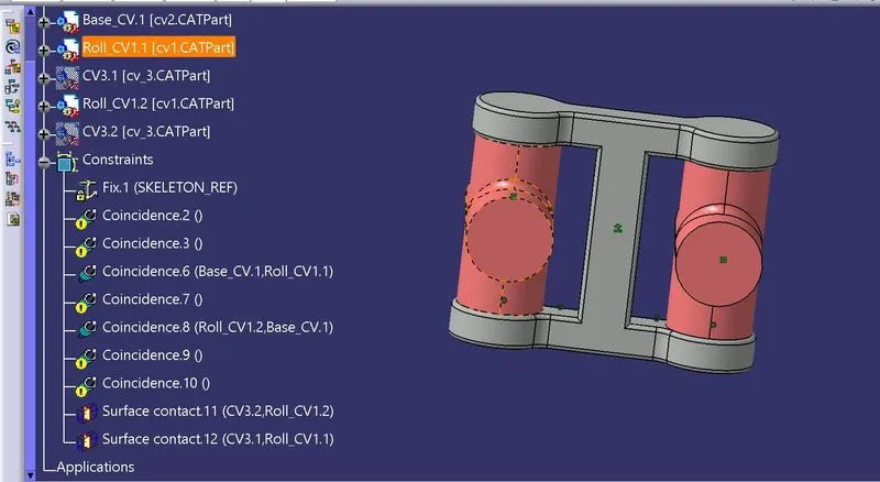
Here the vertical faces of the CV_Roll are connected with the CV_Base.
Then I added the CV_Thumble and made the axis coincidence with the horizontal face of the CV_Roll also made the Contact constraint with surface on it.
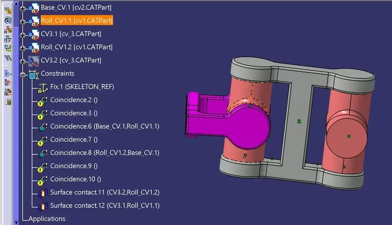
For another one CV_Thumble I made the same procure on the opposite side.
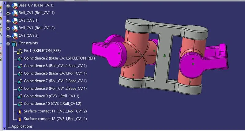
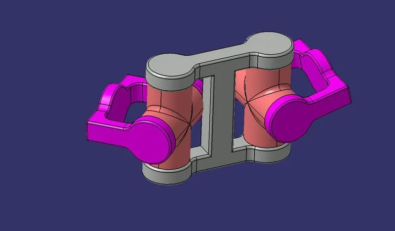
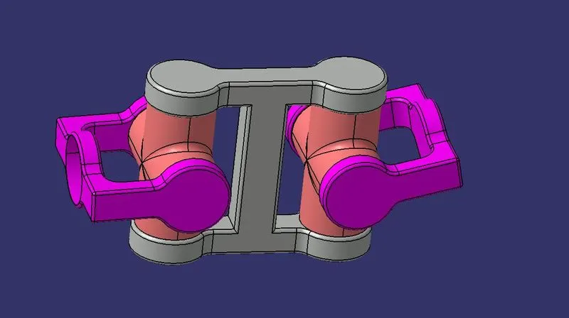
Finally the assembly is made and the various positions of this assembly is shown below.
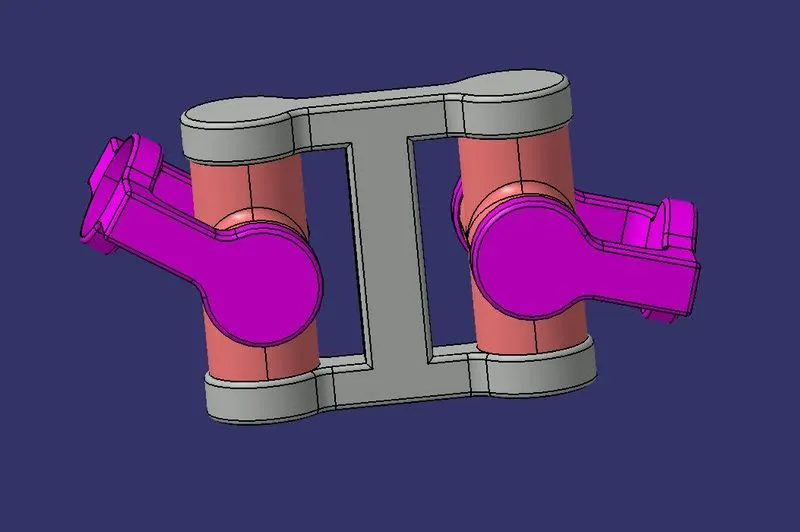
After completed the assembly I created the drawing for this assembly in the drafting workbench which was shown below.