Week 7 Challenge - Assembly Workbench
- DRAWING 1
-
AIM:
To design and assemble a functional quick return mechanism using CATIA V5, based on provided PDF drawings. New CATIA drawings will be created and saved in a designated folder. -
Procedure:
-
Launch CATIA V5 and create a new assembly document.
-
open the provided PDF drawings of the quick return mechanism.
-
Create separate part files for the skotch yoke, fixed base, rectangular slider, connecting rod, and cylindrical slider using Boolean operations for accurate geometry.
-
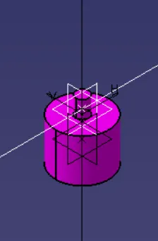
Insert the fixed base part into the assembly document.
-
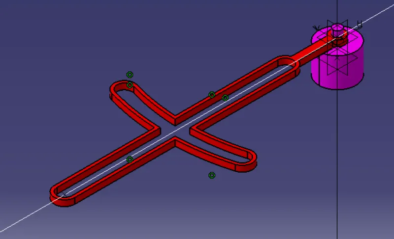
Align and connect the slotted lever to the fixed base, ensuring the orientation matches the provided drawings.
-
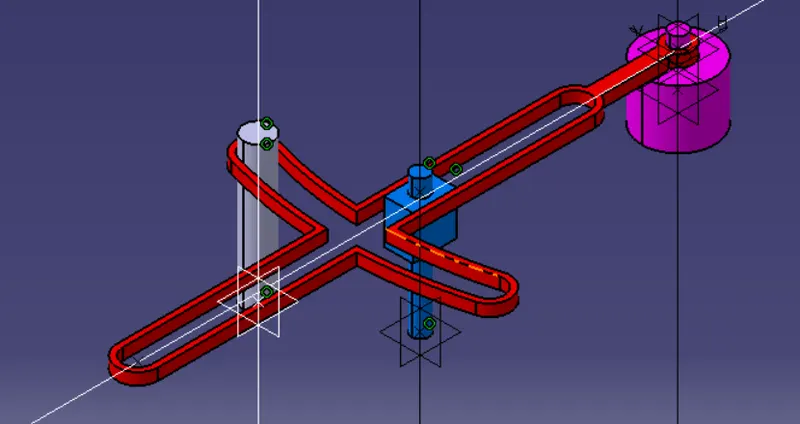
Insert the rectangular and cylindrical slider into the skotch yoke,
-
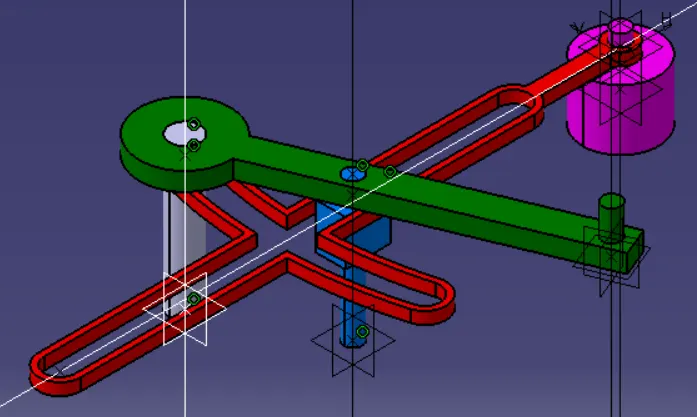
Connect the connecting rod to the cylindrical slider and rectangular slider, applying appropriate constraints.
-
Validate the assembly for interferences or misalignments, making adjustments as necessary.
-
Create CATIA drawings of the assembly, including all necessary views, dimensions, and annotations.
-
Save the CATIA drawings in the designated folder.
-
- Conclusion:
By following the procedure, a functional quick return mechanism can be designed and assembled in CATIA V5. The provided PDF drawings serve as a reference for accurate alignment and part creation. By utilizing Boolean operations, the skotch yoke, fixed base, rectangular slider, connecting rod, and cylindrical slider can be modeled. The assembly is validated for proper fit and functionality, and new CATIA drawings are created and saved in the designated folder for documentation and reference.
-
- DRAWING 2
-
Aim:
To design and assemble a functional CV joint using CATIA V5, based on provided PDF drawings. New CATIA drawings will be created and saved in a designated folder.. -
Procedure:
-
Launch CATIA V5 and create a new assembly document.
-
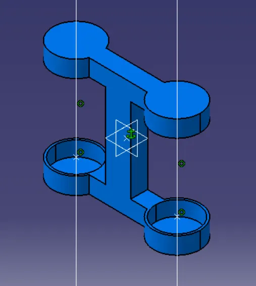
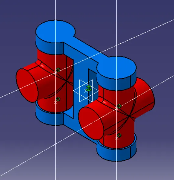
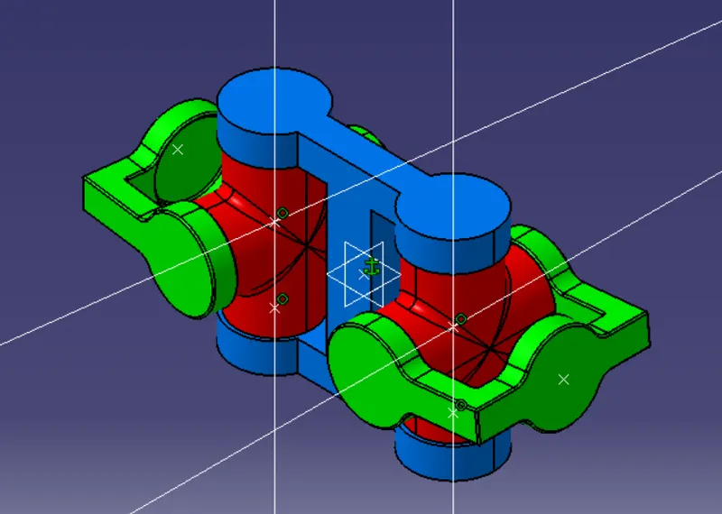
Design and create separate part files for the Cross Spiders, Link Yoke, and Yokes.
-
Utilize appropriate sketches and features to create the desired geometries for each part.
-
Insert the Link Yoke into the assembly document.
-
-
Insert the Cross Spiders and connect it to the Link Yoke, utilizing appropriate constraints.
-
Insert the Yokes and align them with the Cross Spiders and Link Yoke, ensuring proper fit and function.
-
Validate the assembly for any interferences or misalignments, making necessary adjustments to ensure proper fit.
-
Create CATIA drawings of the assembly, including all necessary views, dimensions, and annotations.
-
Save the CATIA drawings in a designated folder
-
- Conclusion:
By following the procedure, a functional CV joint can be designed and assembled in CATIA V5. The Cross Spiders, Link Yoke, and Yokes are accurately modeled and connected, ensuring proper fit and functionality. The assembly is validated for interferences or misalignments, and CATIA drawings are created for documentation and reference.
-