Week 7 Challenge - Assembly Workbench
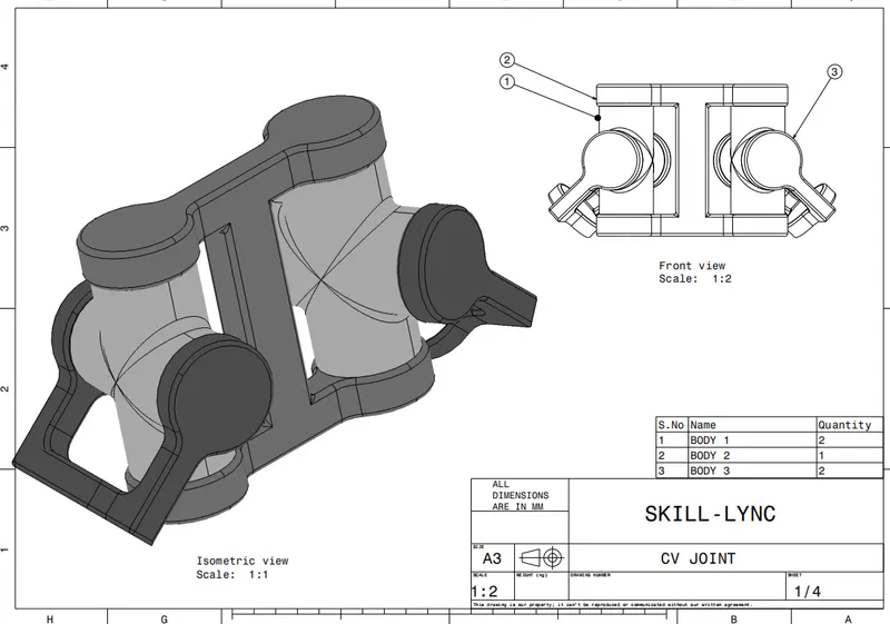
REPORT:-
Step 1: As per sketches provided created part body .
Step 2: Then went to assembly section and called all the parts one by one and renamed them as requirment.
Step 3: constrained four way cyllinder with plane .Then constrained them with four way cyllinder axis with cyllinder holder axis.
Step 4: used coinsident constraine to constrain cap of cyllinder with four way cyllinder.
Step 5:used Explde option to dismental constrained and then refreshed it to check bodies are constrained properly to it.
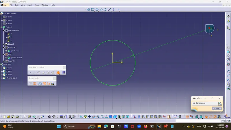
explination > created four way cyllinder by drawing a circle of 50mm dia and pad it by a distance by 100mm and then drew next circle and pad it by 100mm.
take new part drew a circle and mirror it on side of 55mm then drew connector of thickness about 20mm and trimed excess
 portion came out of sketch and pad it for 140mm.
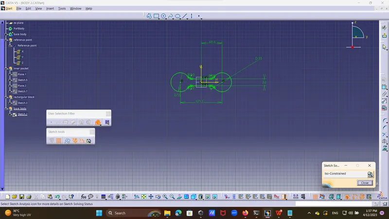
Step 6:Drew a skech of pocket of 100mm and then pad it and removed it form main body .
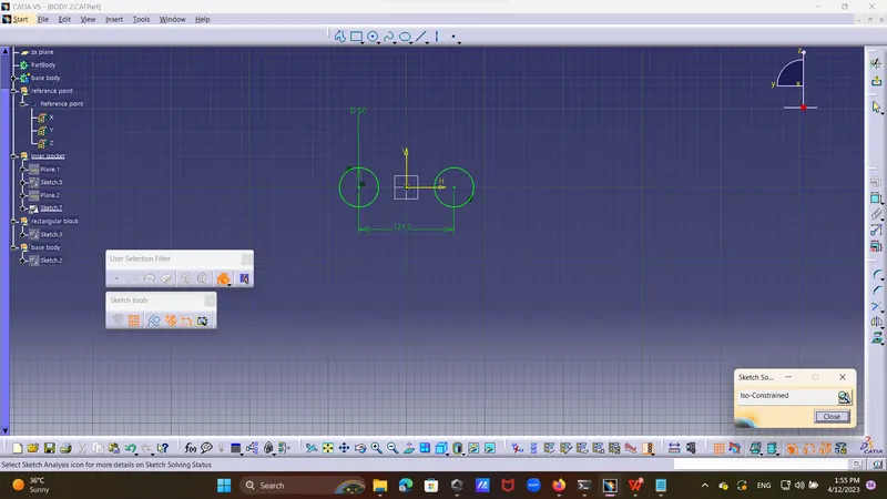
Step 7:drew sepreate sketches for each circle and pocket it from main body to create shell.
Step 8:gave fillet for each fillet of 2.5mm to each edge.
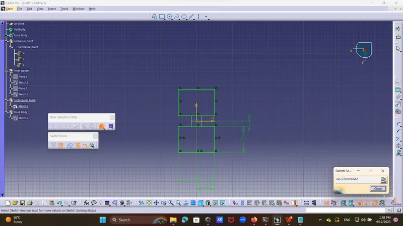
Step 9: drew a sketch of circle of 55mm dia and mirror it on side then drew a horizonal bar of 15 mm and pad it by distance 15mm.drew a circle in it and made pocket about deep of 7mm.
Step 10:drew a side circle of dia 55mm and connector of 15mm central distance of about 75 mm and pad it by distance of 20mm of both side and then made circle and made pocket .
finally fixed the main component
Report on Quick return motion assembly:
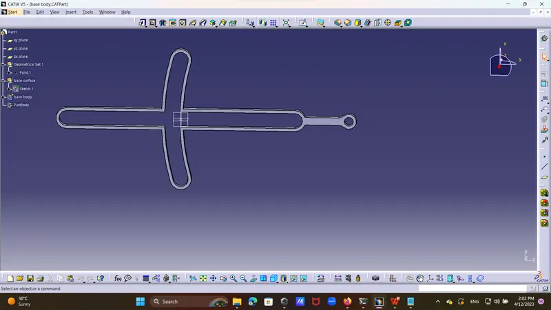
Drew a main body by drawing two circles and joining then by connecting road and trimed them properly.drew two more circles
and on and off side of the of radius of 7mm amd give tangent intersection to them two circles of 152 and 138 mm diameter and then trimed them propery to get desire shape of having thickess about 2mm pad it by distance of 4mm.
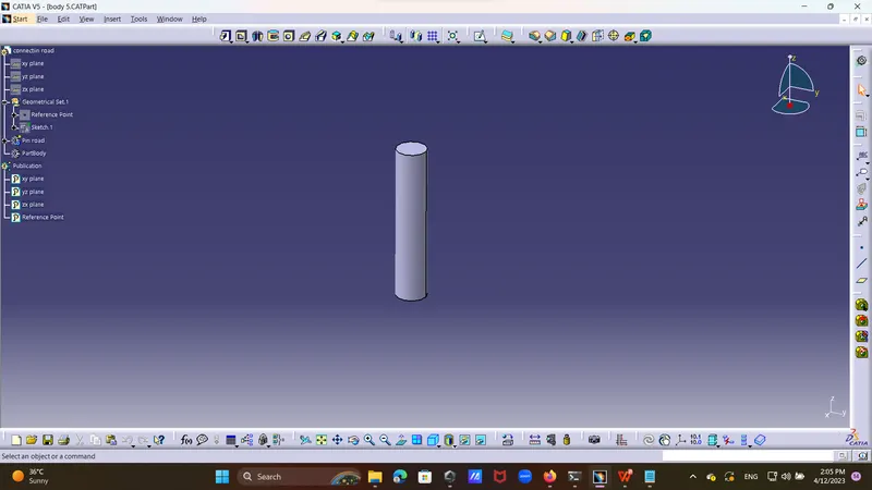
Step 2:drew pin road and pad it by 50mm.
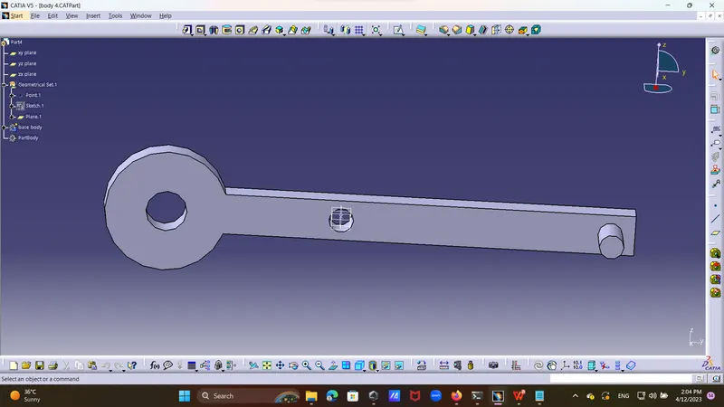
Step 3:cranck drew skech of cranck of radius 15mm and drew connecting rod of 100 mm to join it and trimed it properly, then drew circle on its top and made pocket for connectin rod,
then drew one more circle of radius 3mm and pad it for 10mm then add it to main body.
Step 4:
cinnecting rod drew one connecting rod and by through rectangle 41.5mm down and 5mm up by taking circle on surface of rectangular box.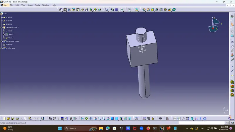
Step 5: drew sketch of roter circle of radius 12.5 mm and then took one more sketch and pad it for 8 mm from top surface of bottom circle.
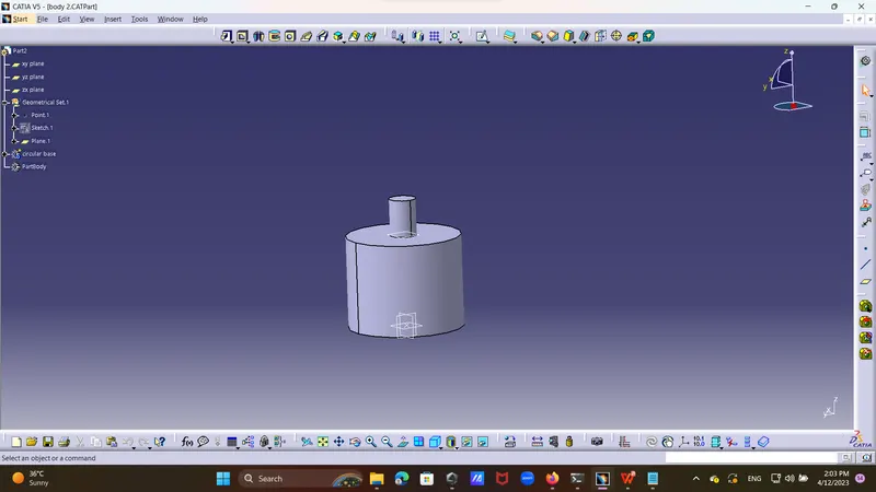
Consrtrins:>> 1] first of all fixed main body
2]made axis to axis constraine and coinside constrain with last hole of body and roter .
3]made axis to axis constraine and of rod and offside circle
4]made axis to axis constraine and coinside constrain with cranck shaft with connecting rod .
5]made axis to axis coninside constrain of supporter rod and crank shaft and surfac to surface coinside constrain,
then constrained coinside of supporting block with bottom surface
by taking exploding option checked if constrain done properly done or not.