Week 7 Challenge - Assembly Workbench
ASSMBLY WORKBENCH
OBJECTIVE:
To create assemblies of Quick return mechanism and CV joint and to also create 2D drawing of the given assemblies copmponents.
TOOL USED: CATIA V5
PROCEDURE- ASSEMBLY DESIGN
1)ASSEMBLY OF QUICK RETURN MECHANISM & ITS DRAFTING
QUICK RETURN MECHANISM
A quick return mechanism is an apparatus that converts circular motion into reciprocating motion in presses and shaping machines, which are utilized to shape stocks of metal into flat surfaces. This mechanism is mostly used in shaping machines, slotting machines and in rotary internal combustion engines. The word quick return indicates that the returning stoke is faster than the forward stroke which help the tool to retrieve back faster after doing a particular job. Quick-return mechanisms feature different input durations for their working and return strokes. The time ratio of a Quick Return mechanism is the ratio of the change in input displacement during the working stroke to its change during the return stroke.
Let us create Assembly modeling in which deals that inside multiple files that represent components within a product. The components within an assembly are represented as solid part dodies or surface models.
INPUT: Reference Drawings of Assembly and its parts.
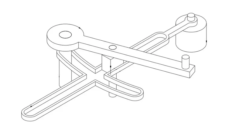
STEP_1: PART MODELING
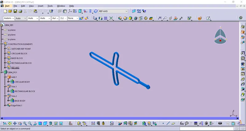
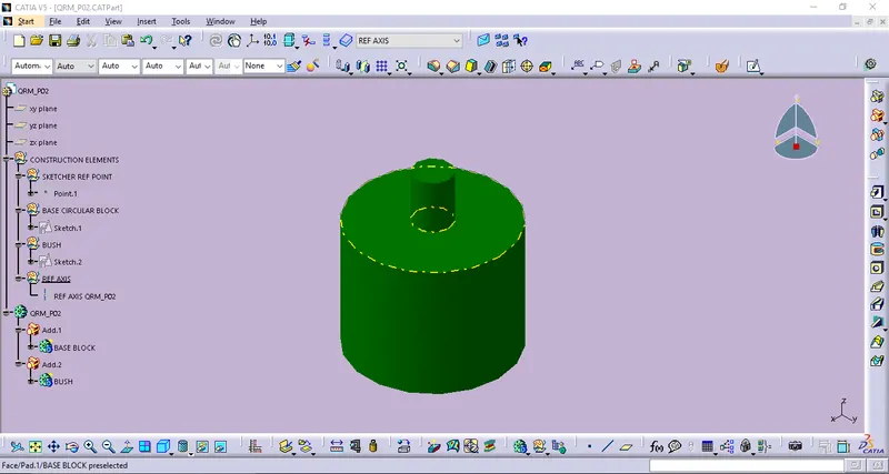
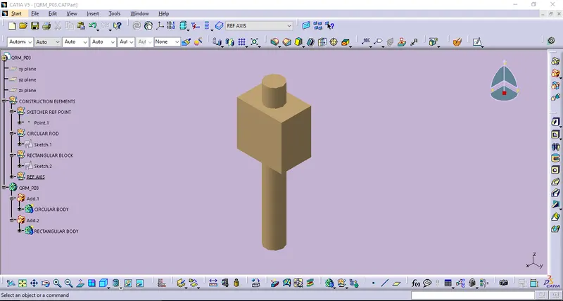
Thus all the Part modelings of this assembly components are considered thus the following this,
- Creating all the following sketches of the respective parts are created by using positioned sketches. And,
- All the sketches becomes iso- constrained sketches defined by using sketch solver.
Let us consider here thus all the part models becomes created by using following features of Part workbench,
- Sketcher workbench(Positioned sketches & Iso-Constrained).
- Sketch based features & Dress-up features, And
- Boolean Operations(Add,Remove,Union Trim,..)
PART-1_QRM_P01
PART-2_QRM_P02
PART-3_QRM_P03
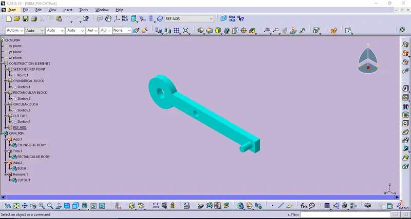
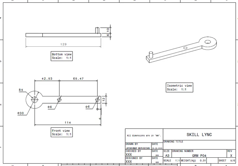
PART-4_QRM_P04
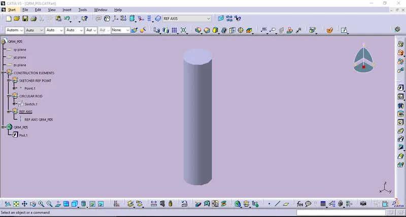
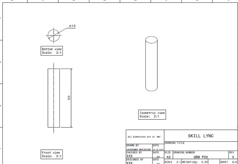
PART-5_QRM_P05
STEP_2: ASSEMBLY WORKBENCH
While using on Assembly workbench by following the below steps which will makes easier to obtain the resultant model of Assembly Component.
Create a new CATproduct and the insert respective Parts of Assembly components.
Create a reference elements like axis, points for all Parts.
By using publication tool that helps us to showcase all the refernce elements like planes,points,axis that will be easier to pickable.
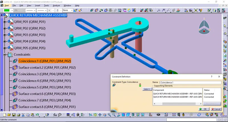
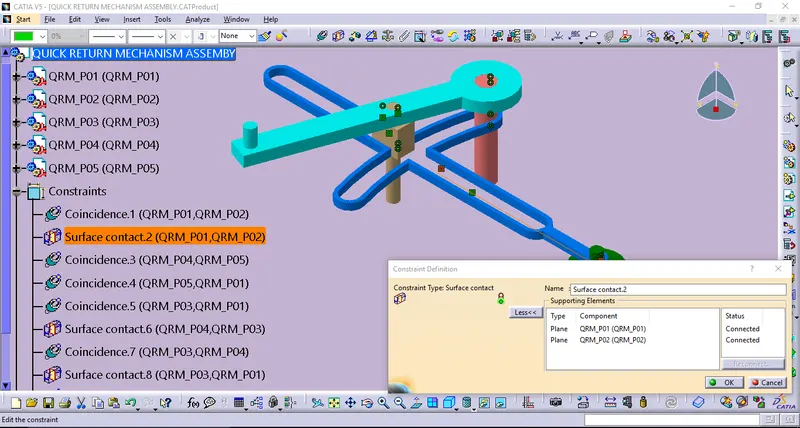
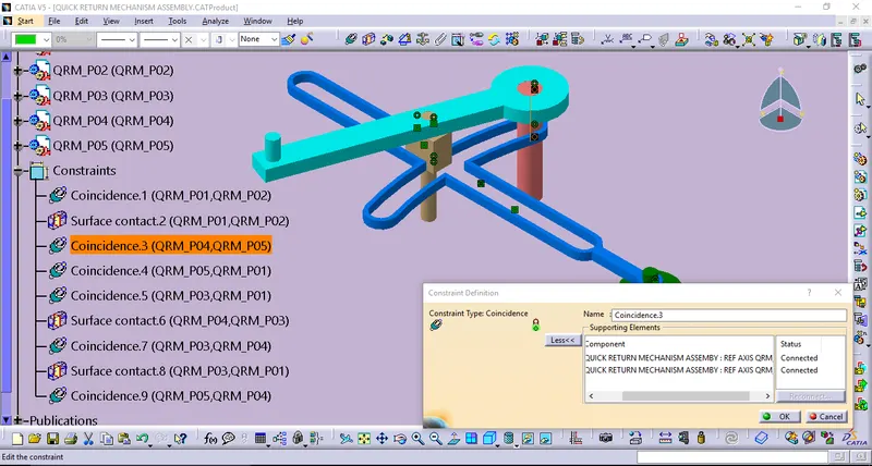
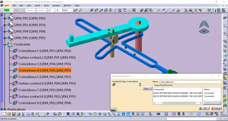
And then by using constraints like CoinsidEnce,Surface contac,& Fix.
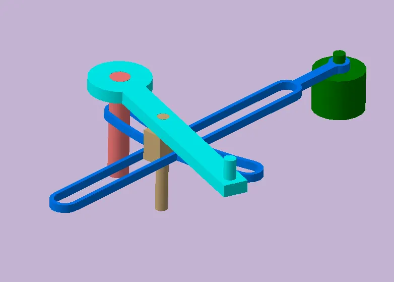
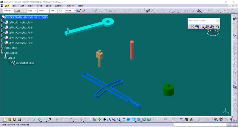
And some of the followings of Quick Return Mechanism Assembly are,
VIEW ORIENTATION:
ASSEMBLY VIEW
EXPLODED VIEW
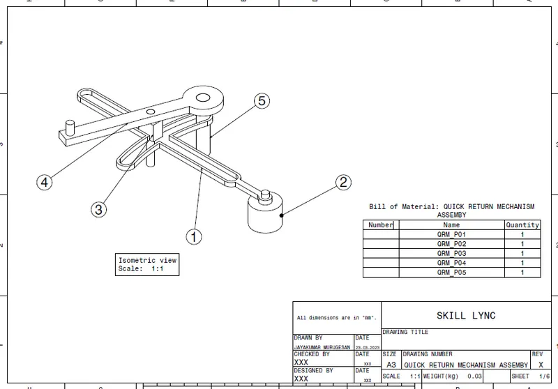
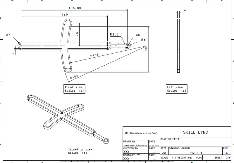
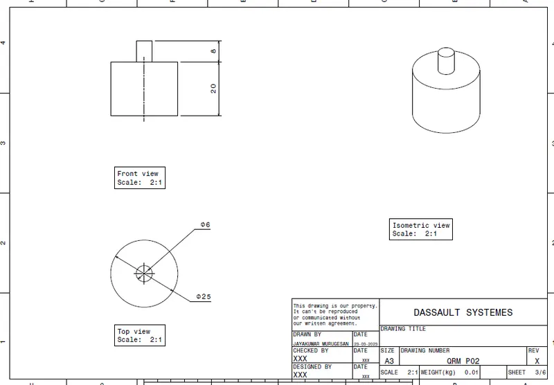
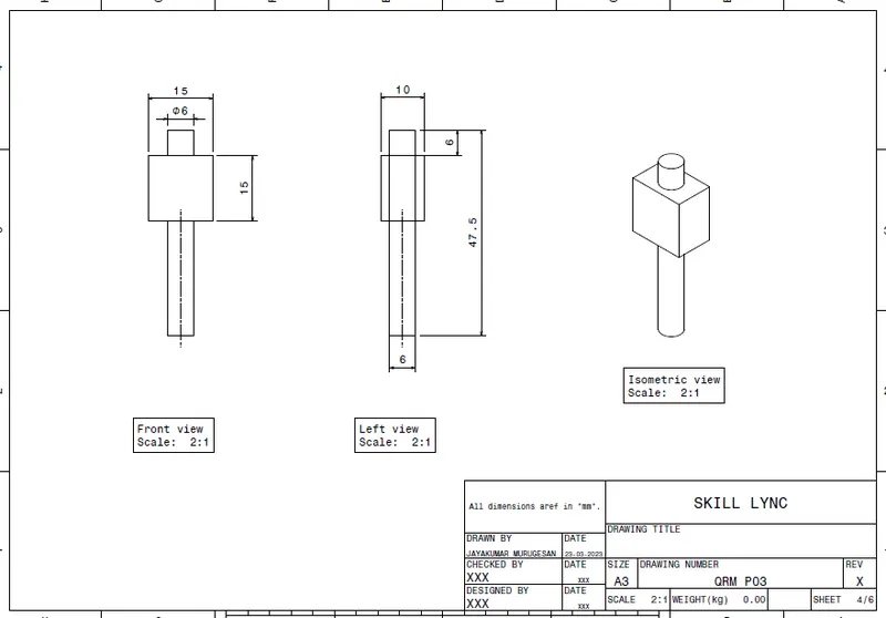
DRAFTING OF QUICK RETURN MECHANISM ASSEMBLY:
2) ASSEMBLY OF CV-JOINT AND ITS DRAFTING
CV-JOINT
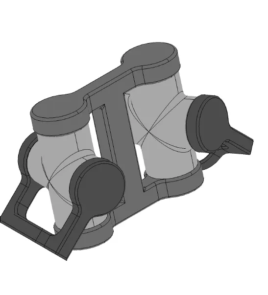
CV joints are part of the driveshaft and are used primarily on front-wheel drive vehicles, but they are also used in rear- and four-wheel drive vehicles. CV, joints are used to connect your vehicle's transmission to your wheels.
INPUT: Reference Drawings of Assembly and its parts.
STEP_1: PART MODELING
Thus all the Part modelings of this assembly components are considered thus the following this,
- Creating all the following sketches of the respective parts are created by using positioned sketches. And,
- All the sketches becomes iso- constrained sketches defined by using sketch solver.
Let us consider here thus all the part models becomes created by using following features of Part workbench,
- Sketcher workbench(Positioned sketches & Iso-Constrained).
- Sketch based features & Dress-up features, And
- Boolean Operations(Add,Remove,Union Trim,..)
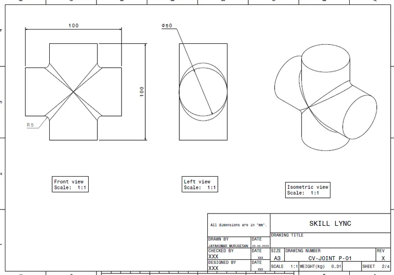
PART-1_CV-JOINT_P01
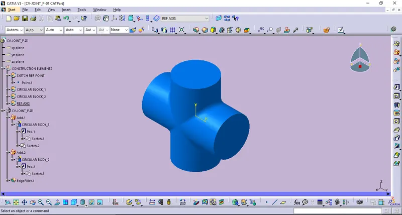
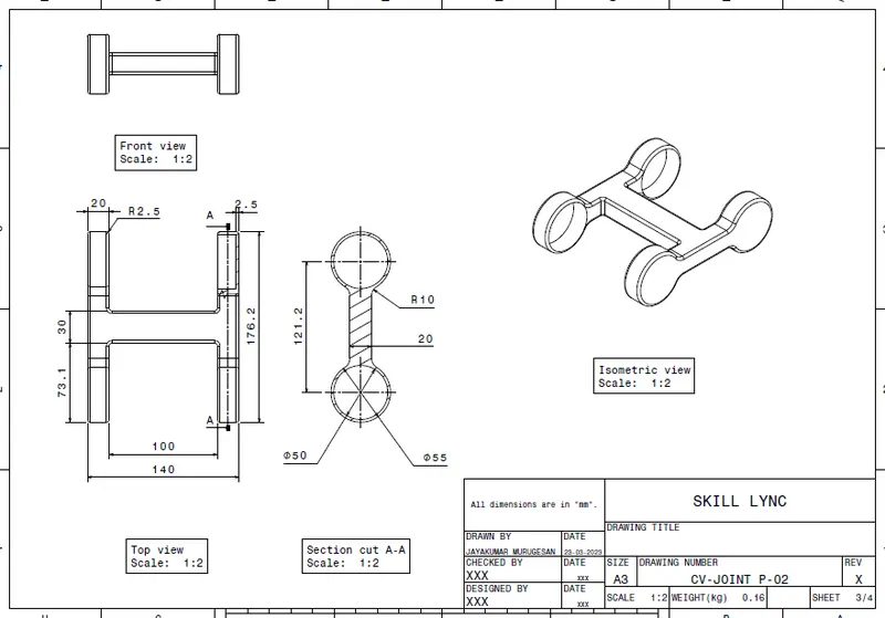
PART-2_CV-JOINT_P02
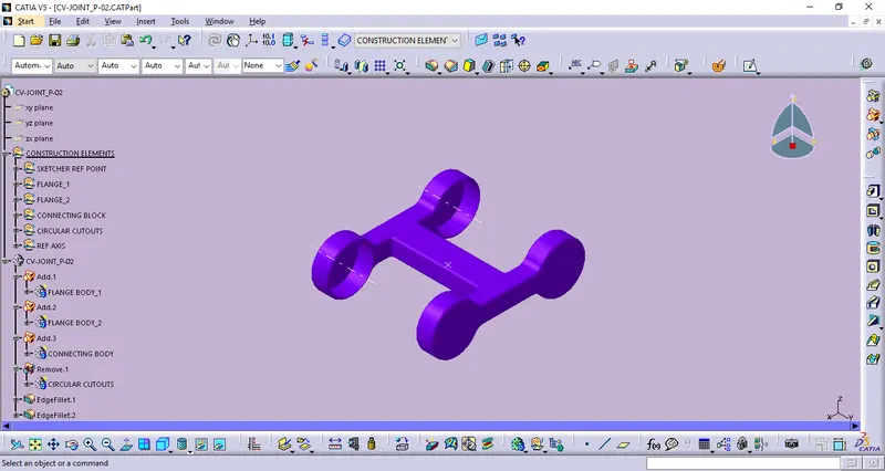
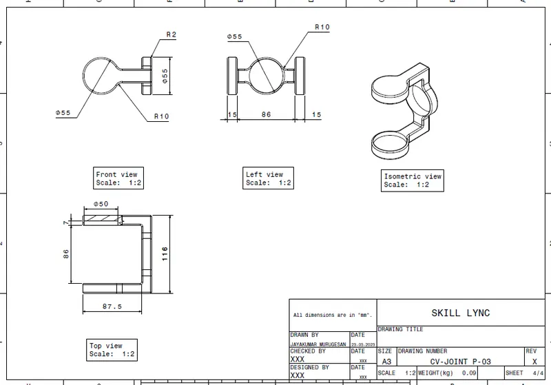
PART-3_CV-JOINT_P03
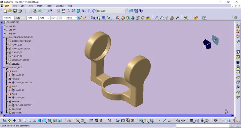
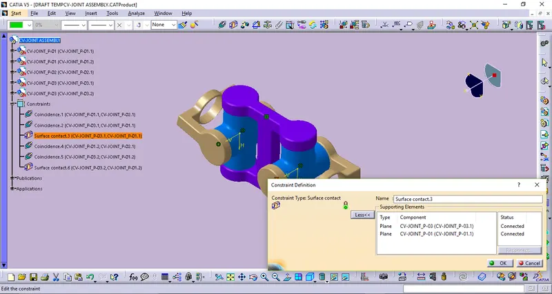
STEP_2: ASSEMBLY WORKBENCH
While using on Assembly workbench by following the below steps which will makes easier to obtain the resultant model of Assembly Component.
Create a new CATproduct and the insert respective Parts of Assembly components.
Create a reference elements like axis, points for all Parts.
By using publication tool that helps us to showcase all the refernce elements like planes,points,axis that will be easier to pickable.
And then by using constraints like Coinsidence,Surface contact, & Fix. And the followings of assembly work bench,
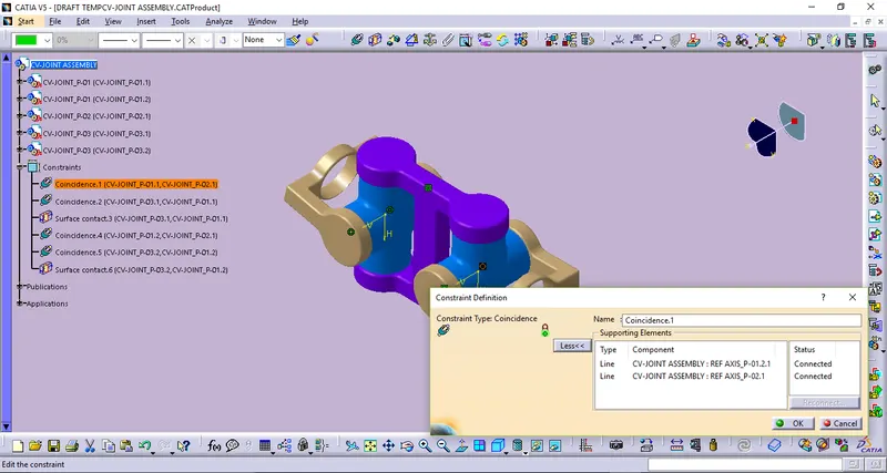
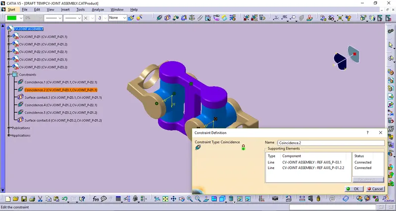
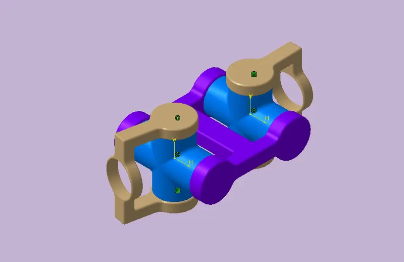
VIEW ORIENTATION:
ASSEMBLY VIEW
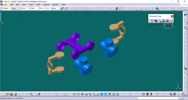
EXPLODED VIEW
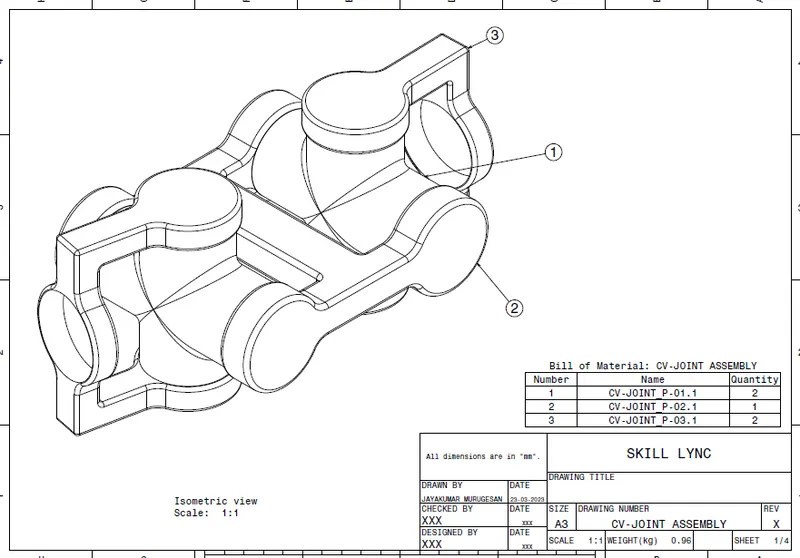
DRAFTING OF CV-JOINT ASSEMBLY:
CONCLUSION:
Part Modeling of Assembly Component are done by using CATIA Part Workbench.
Assmblies of Quick Return Mechanism & CV-joint are successfully created by using the CATIA Assembly workbench.
And also the Drafting of both the Assembly Copmponents are completed by using CATIA Drafting Workbench.