Week 7 Challenge
1. Introduction :-
Water current forces are thoses forces which are effect the bridge due to water current load . For calculate the loading due to water trust the effect or loading on bridge pier are calculated are known as water current forces.
water current forces are calculate with the help of mean velocity of river or canal .
2.Aim :-
Here we find out the effect due to water current of Bridge Pier or some times it effect whole structure .
3.Procedure :-
For find out the the effect due to given data on Bridge we need some data to calculate the loading due to water current
as here
Span length of Bridge - 45m
water flood level h - 2 mtr
Mean velocity of river - 3m/sec
assume
1. as showing pic only pier effect due to water current forces
2. Pier are recangular 2mtr
so,
Vmax =2^0.5*3
=4.242
Water Pressure
p= 52kv^2
=52*1.5*(4.242)^2
=1403.576 Kn/M2
Now get the loading due to water current
Now this loading will apply on given bridge data ,so draw the model in staad pro and apply the loading
1. before create the model we need the file name and location provide as here we provide as loading as water current and location and click on "create "
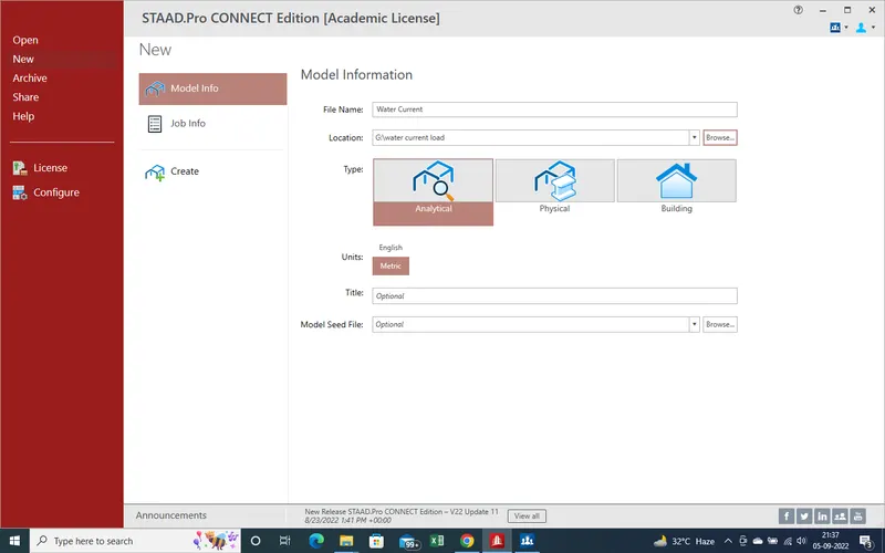
2.As we click on "create " a new window has been open as showing in given pic .
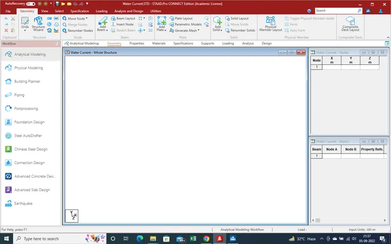
3.Create the model for Abutment as showing given pic .
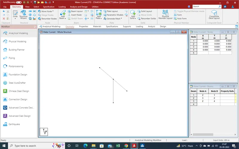
4.As here given pic we get the model with main girder and pier shaft . now create the plates for slab section at given model
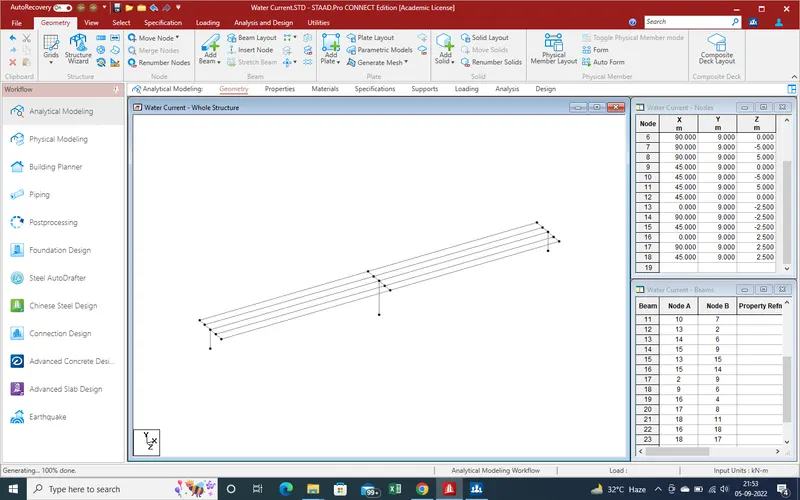
5.Model has been crated now need to apply the properties for model components .
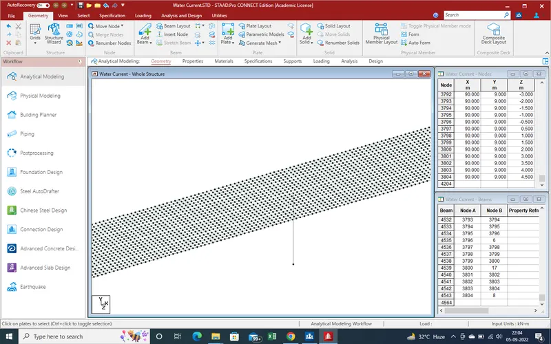
6.Here as we already assume that pier are rec and its diamension are 2X2 mtr so define first proprtiy of pier as showing in given pic.
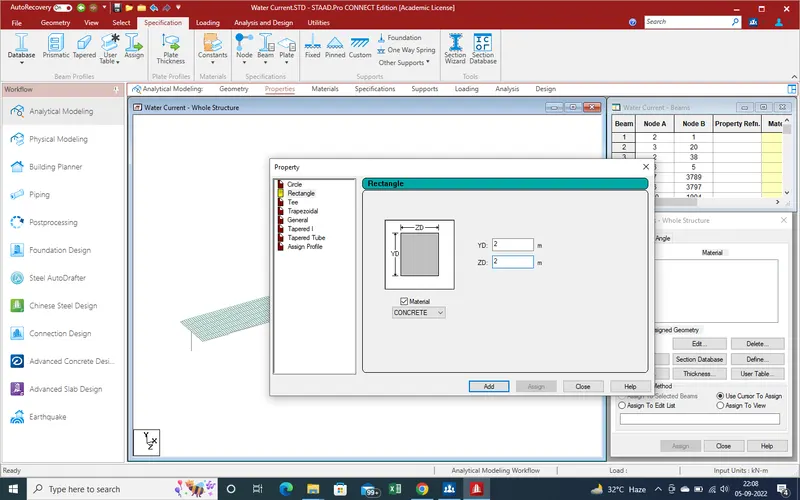
7. Click on "add' and property has been added to property section . same as properties defines for master beam secondary beam and slab section
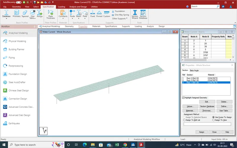
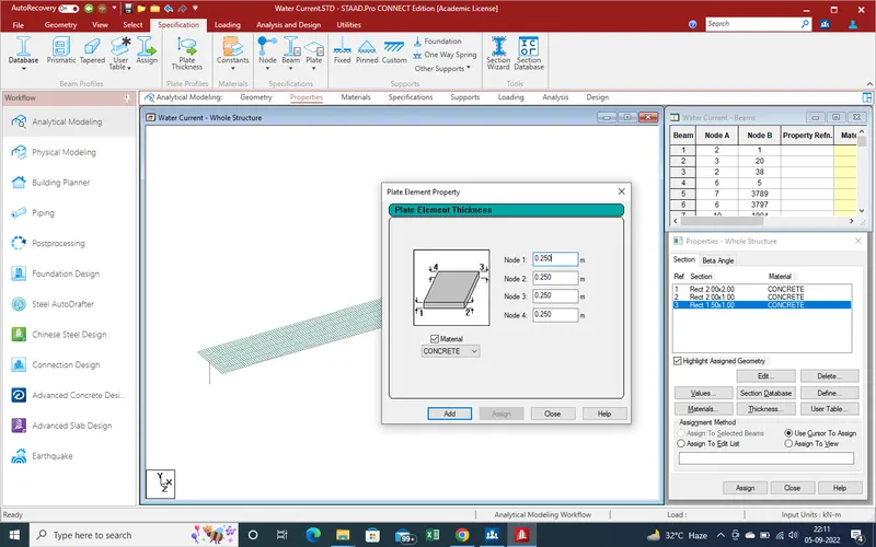
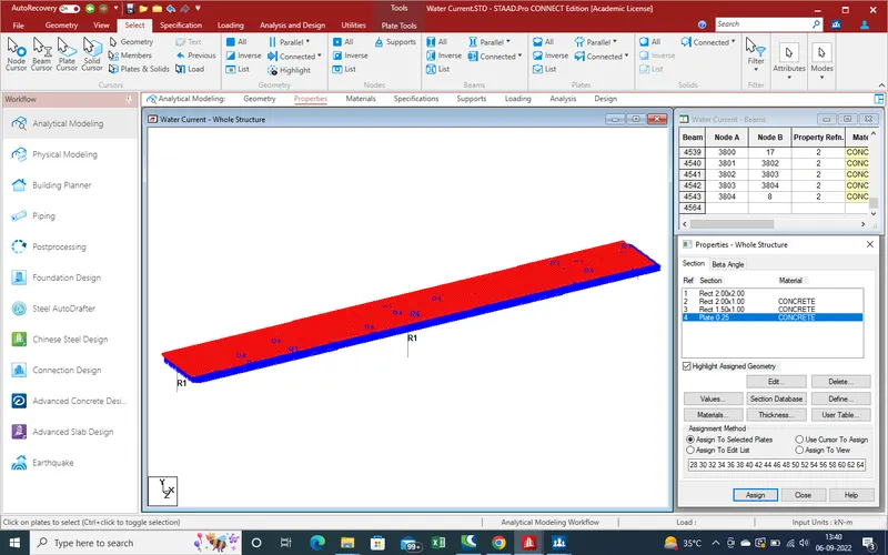
8. Plates proprty define
9.Now assign the given property for pier .
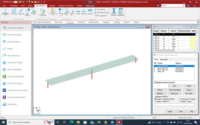
10.Assign proprties for main beam /cap and the get the results as showing in given pic .
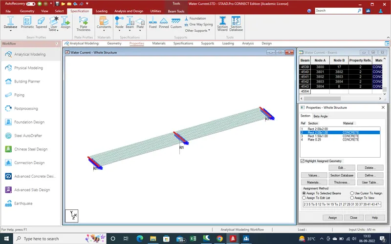
11.Same as here we get the results due to apply the property of plate thickness as showing in given pic .
12.Now create the support as pier and abutment are under ground upto 2mtr so simply apply the fix support
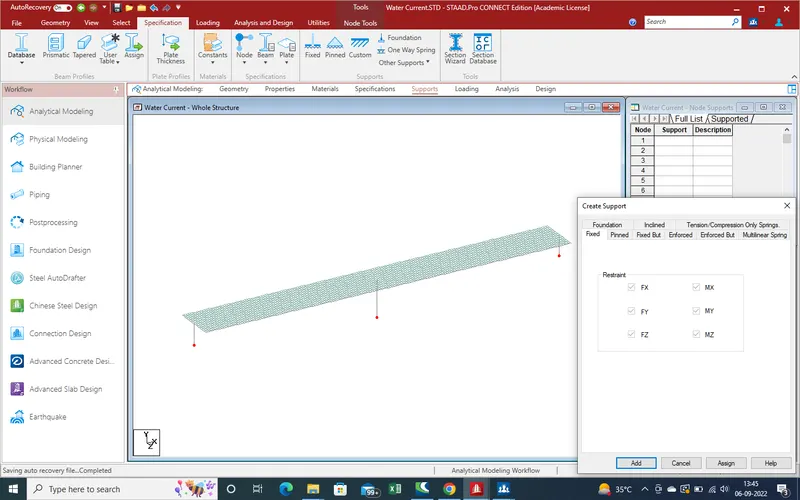
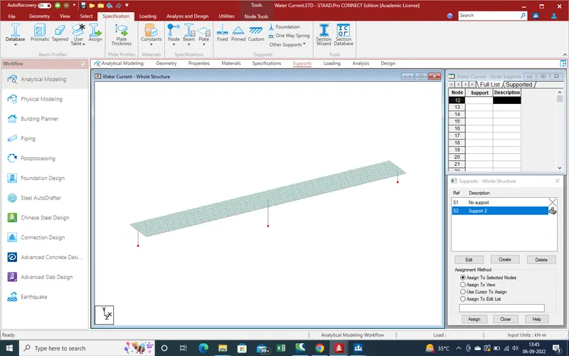
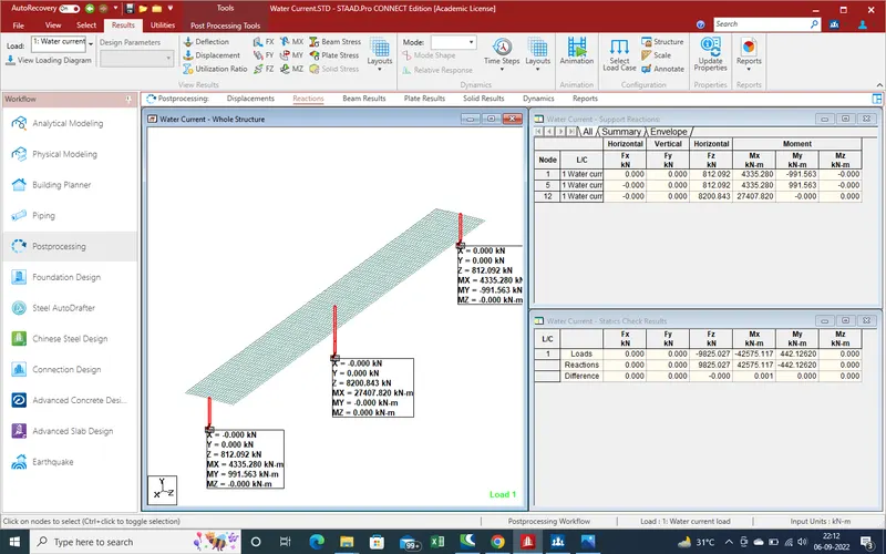
13.Now get the results due to support rection application
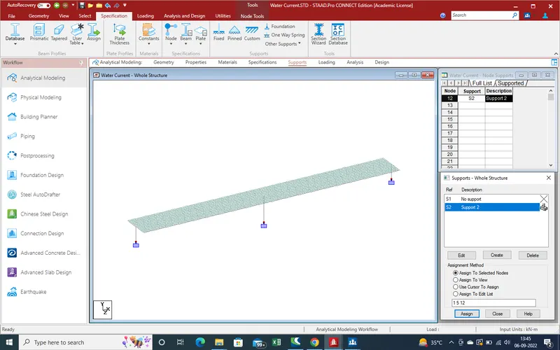
14. Now We apply the loading due to water current forces.
as we have already calculate the loading , here we need the create before apply loading area or length on the pier shaft .
here pier shaft is 2mtr is under the ground , so create need the load 2 mtr from base and second end point is 2mtr due to HFL value is 2mtr from ground .
so follow the steps showing in pic .
15.Go to loading section
select the load case details and click on "add"
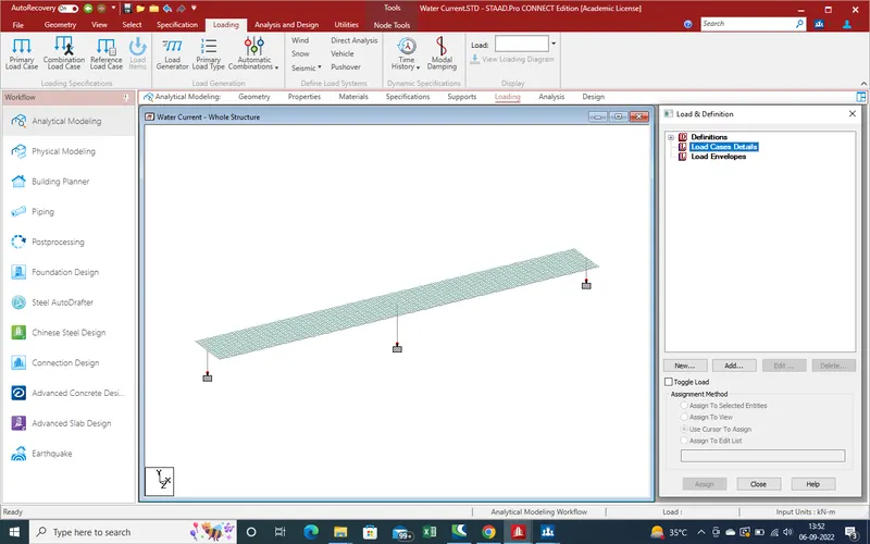
16.A new window has been apear
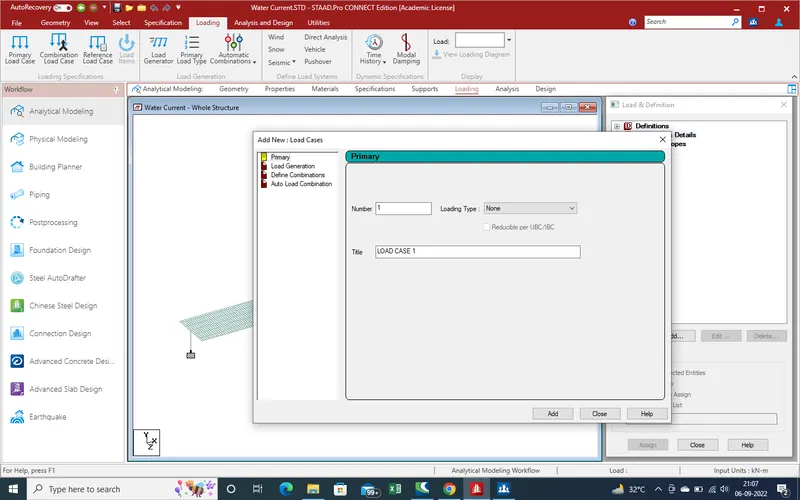
17. Give the name for load case as here "water current load"
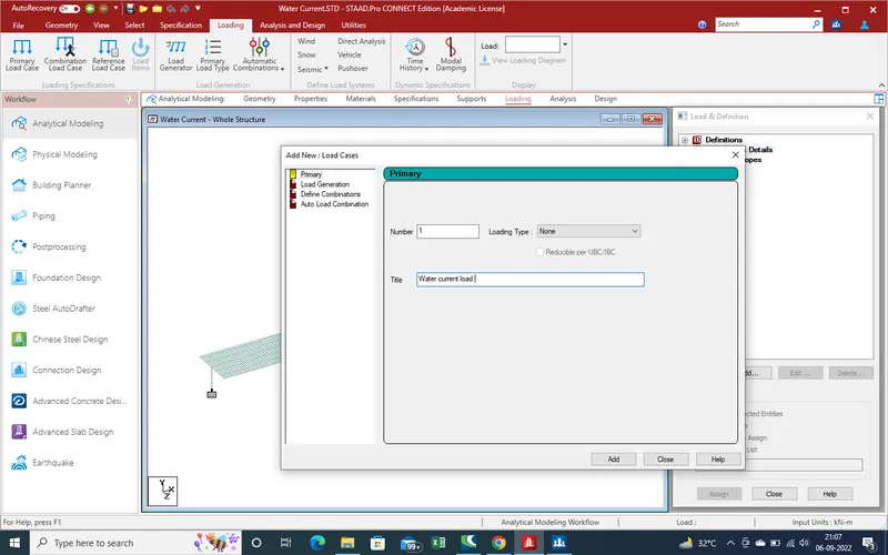
18.Add and close the window new load case has been apear as showing given pic
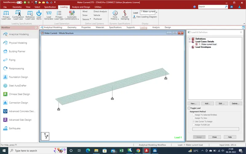
19.Again Select the created load and click "add" .
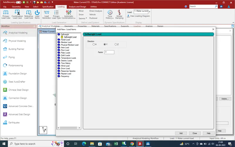
20. As water current load we calculate as area unit but here we have beam as pier so load should be change in kn/m so here modify the value of loading as
=1403.576kn/m^2
width of pier is 2mtr so for unit loading
value for unit width =(1403.576*2)
=2807.152 Kn/m
Put the values as member load with varies from max to zero for bottom
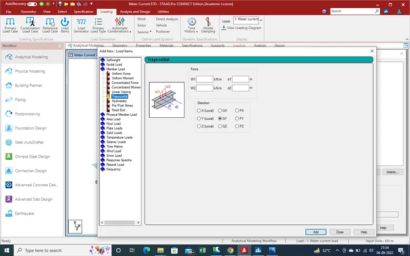
21. Put the values as
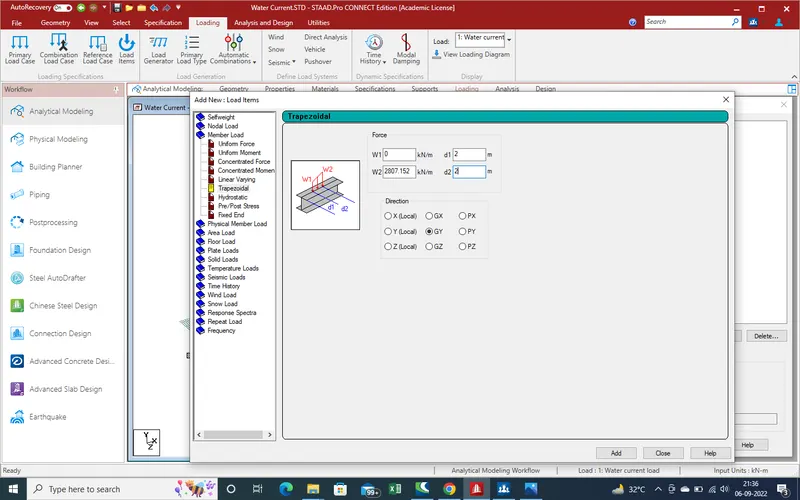
22. Click on "add" and close the window
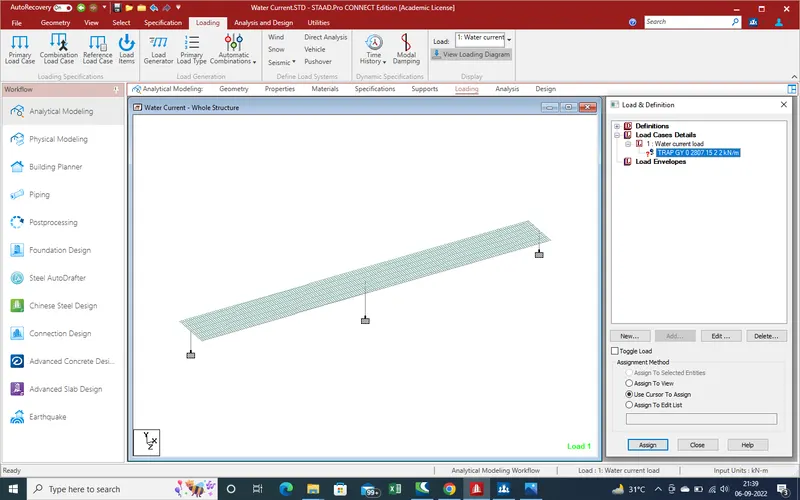
23.Apply the load on Pier due to Abutment are out of range of water logging area
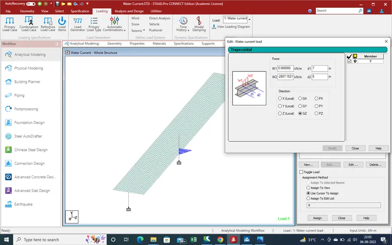
here values are in - due to direction
24.Check the perform run analysis
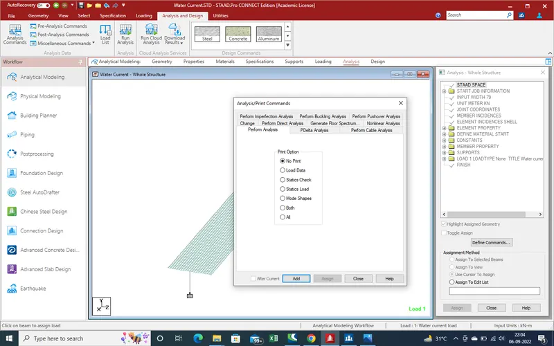
25. Run the analysis the model
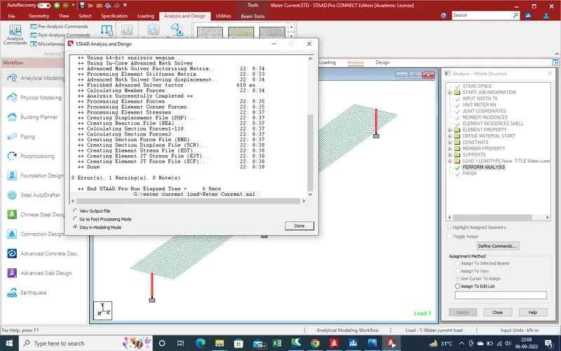
there is no error so go to post processing mode for get the results
4.Results :-
1.Displacement due to water current load
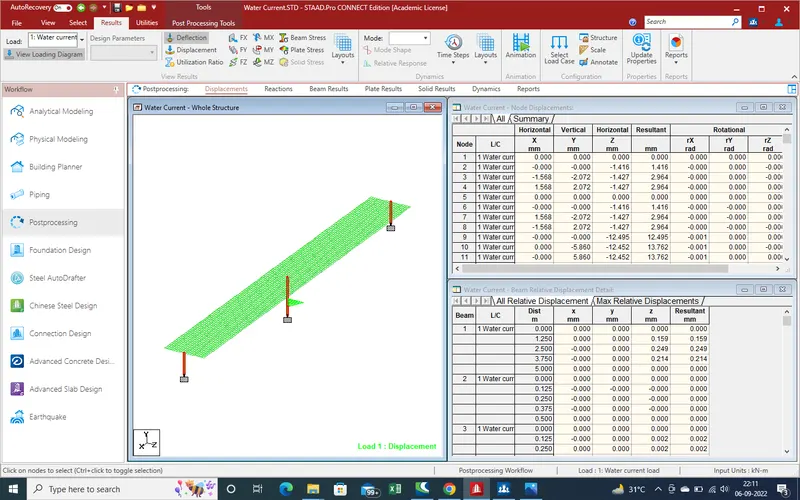
2.
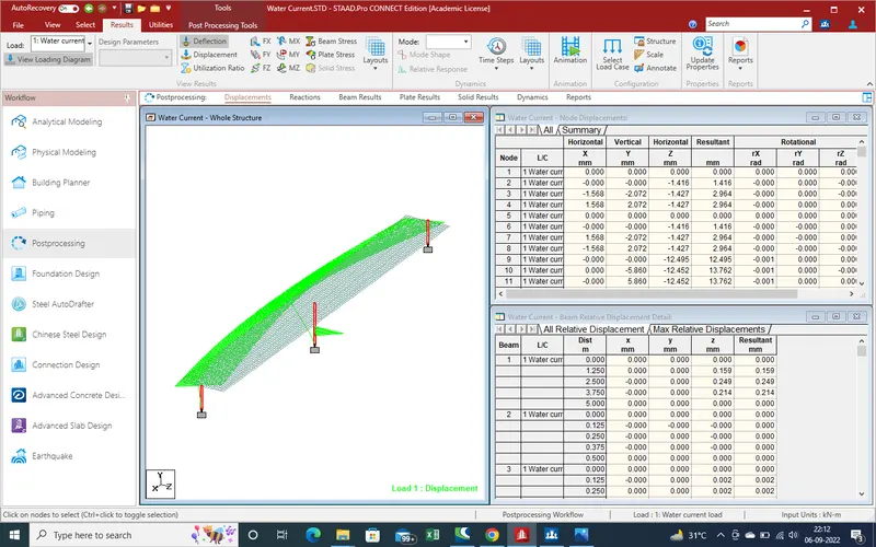
3.Support reaction
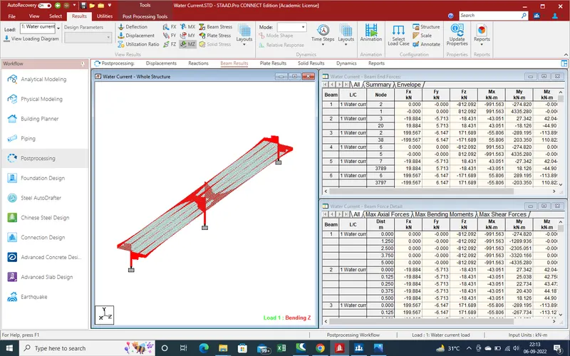
4.Beam Results
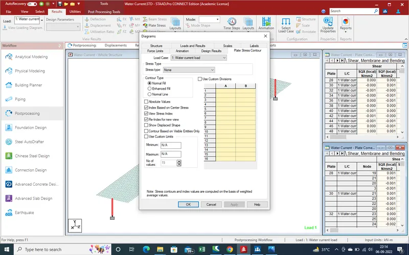
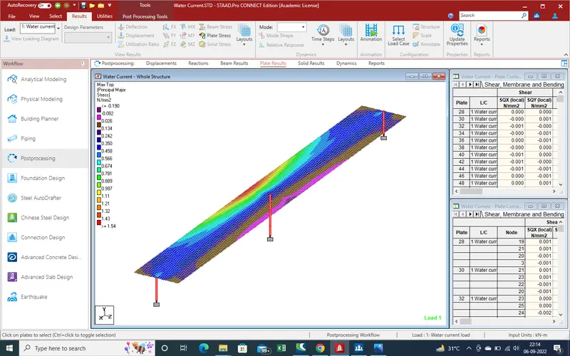
5.Plates results
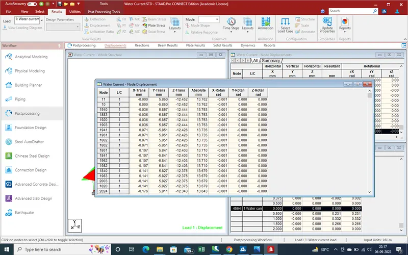
6.Node displacement report
7.Beam shear forces
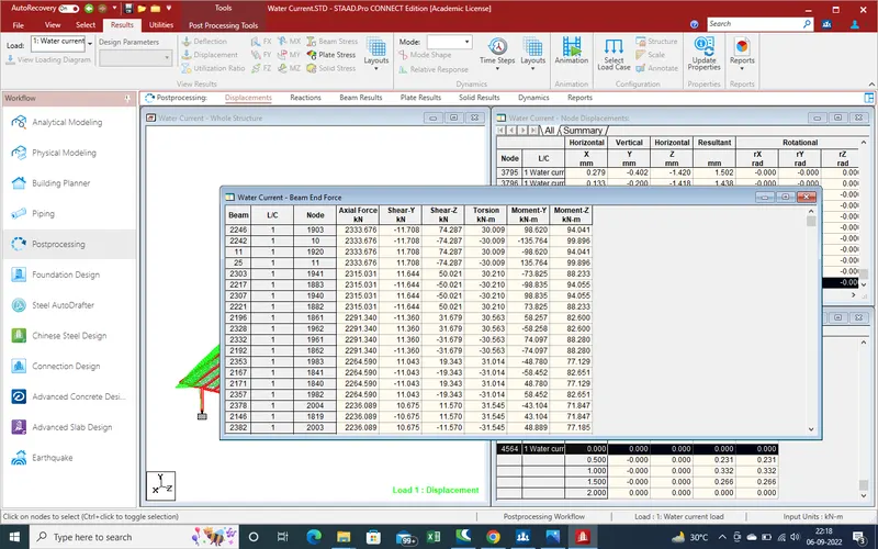
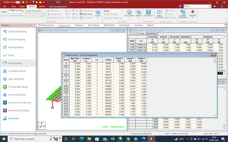
8.Beam Displacement
9.Forces on beam
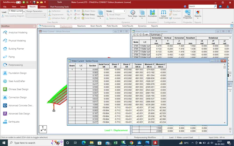
10.so we can found out other all reaction due to water current load .
for further checking find the attached sheet of model for checking