Week 7 Challenge
Q1. Create profile model for innermost shape
Aim & Introduction.
The aim of the section is to design a vertical profile with ORD.
Procedure.
Procedure for creating the profile model will be discussed below.
Open ORD => T&E and TI
Browse the horizontal alignment C/L file from the previous work=> go to Vertical=> Complex geometry=> Profile => complex by elements=>a small window appears=> method=>select automatic=> FD=>assign active FD and name it as PGL01
Go to reference attach window=>attach eterrain file from the Survey folder=>attach with live nesting depth 1=>now click on the view 8 => profile window opens up=> go to view and arrange both models in the same display=>click on the eterrain model and flyout menu appears=>select set as active =>now go to profile window and fit view=> now the actual profile data appears on the screen=> turn off the eterrain display as the now the plan and profile linked together.
Now we can see the profile for the highest and innermost profile details from the profile window.
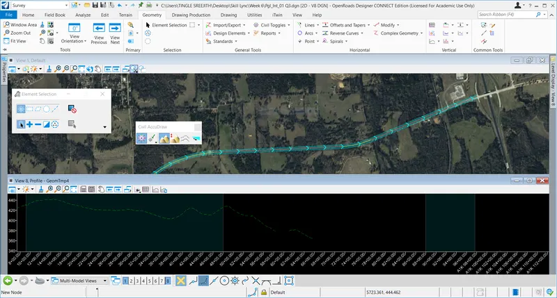
The procedure for creating the profile for the innermost shape (C/L) has been explained below.
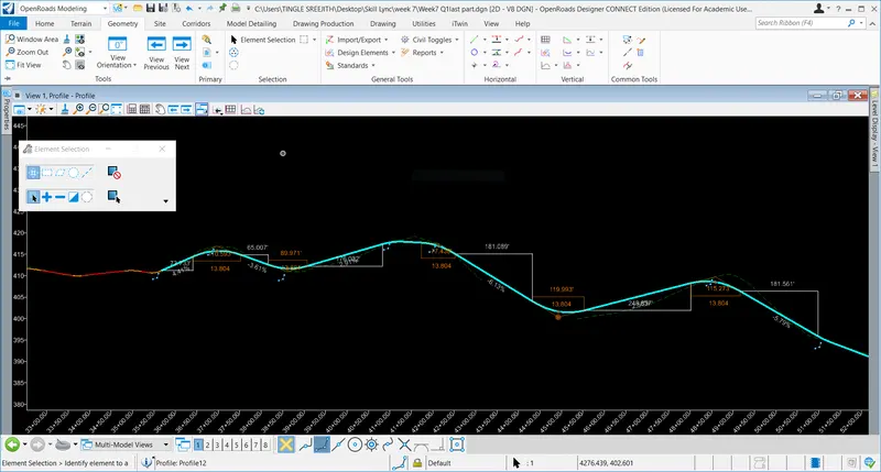
Go to vertical=>complex geometry=>complex by PI=> draw lines as close to the existing ground and edit the curves=> go to curves=>profile curve between elements=>circular curve between elements and make the curves smooth.
If the element has multiple parts then make it complex by first exploding all elements with Drop element command and then re-joining it with Vertical=> complex geometry=>complex by elements =>assign FD=>use active feature=>select elements
Or the same can be done using 'Key In' and Rebuild method
Finally, one more option can be applied to the profile by =>Vertical=>modify=>Append profile element=>first locate the complex element and follow selection of simple elements
As a last step=>select vertical profile element=>flyout menu=>set as active profile
Now open Civil accudraw tool=> keep it in the plan view=>drop down menu=> click eswitch dialogue mode=>now the Z value can be seen in the profile window while touching the lowest point.
Also, create a profile report=> select the element=>flyout menu=>profile report=> report generated.
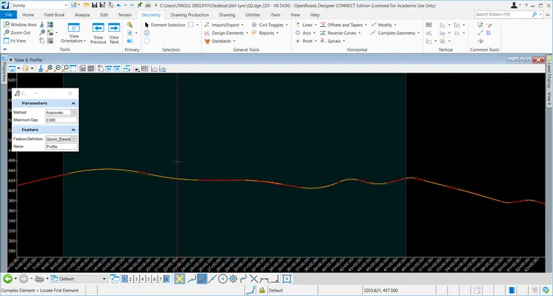
In order to develop the profile at constant elevation=> Open the same model with eterrain file attached in it=>draw a straight line with Horizontal=>Complex by PI=>FD=>Geom Base line=>click on the element=>Flyout menu=>Generate profile view=>Go to Profile view and draw line with FD=>Geom Base line=>complex by PI draw the lines with appropriate curvature
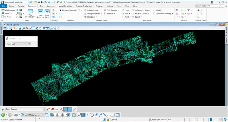
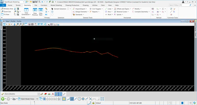
Results
Thus, the profile details for the innermost shape and profile at constant elevation can be developed.
Q4. Change the designed profiles for all the shapes with constant or variable slopes of desired values.
Aim & Introduction
The aim of this question is describing the ways to draw profile shapes with constant and variable slopes with ORD.
Procedure
The procedure for drawing the profile lines for all shapes with constant or variable slopes has been described below.
Open ORD=> Open the same file with profile lines for constant horizontal lines=> Open the profile view
Go to element selection=> select the profile element => change the profile lines with civil rules by changing the slope percentage=> Change the curves using the civil rules
This procedure can be done for any profile shapes with constant or variable slopes.
Results
Thus, the profile line can be modified for constant or variable slopes.