Week 3 Challenge
Q1. Create a terrain by various Methods.
Aim and Introduction.
Terrain creation is an important part of Openroads Designer, and it can be done by various methods depending on the data availability or sometimes it depends on the situation. Terrain can be created from a file, by ASCII, by Graphical Filter, by Text interpolation and by elements. This session will explain only 3 options of terrain creation and rest will be explained in the following weeks.
Q 1.1 Terrain creation from file
The steps involved in the terrain creation from file are listed below.
Open ORD=> select Workspace Training and Examples=> select Workset=> Training Imperial
Open new file=> select seed file 2D imperial=> Name the file=> file opens up
Go to Terrain=> Create=> click From file => Browse files=>select Survey DTM file=>Import (with File options, source file options and Feature Definition - existing contours and Triangulation option -Import Terrian only)
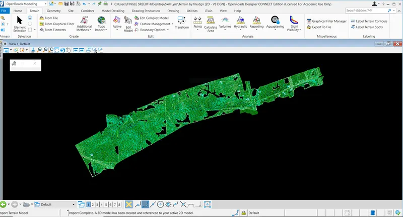
Import complete message appears on the window=> Do fit view and the terrain appears on the screen and a default 3D view is also created along with this terrain model.
This method can be done with various file formats like .TIN and .XML etc and the attached terrain model below is done by superimposing the .TIN file with feature definition existing Thematic height on the terrain created by the .DTN file.
Results
Thus, the Terrain from File procedure is done.
Q1.3 Terrain creation from graphical filter
Creating a terrain from a graphical filter can be done by the following steps.
Open ORD=> Training and Examples => Training imperial
Create a new file with 3D seed file=> Name the file => Blank file opens up
Go to Terrain=> Click Create From Graphical Filter=> New window opens up=> Click on the Terrain filter manager => Create Filter group (terrain by graphics) by right click=> same way create filers named Spot and Breakline by right click
Close the window and click element selection => go to survey folder=> select 3D survey graphics (interactive method).
New window pops up=> all settings remain same=> hit Ok=> load file=> Fit view
Go back to From graphical filter tool =>Terrain filter manager=> select feature type spot=> click Edit filter=> a new window pops up=> go to colours => levels => select the level number from the drawing (eg: 38) => add=> Finish
Same way Go to Filter Breakline and => Edit filter=> select multiple levels (as seen in the drawings) => add => finish
Go to Filter group terrain by graphics => select filters=> spot=> Finish
Click the blank rectangle symbol button => new window pops up=> select Graphical filter terrain by graphics
Now left click on the drawing and accept
Go to triangulation options=> select Max Triangle length=>Max triangle side length
Feature=> Feature Definition => select existing triangle=> select Terrain by graphics=> left click and accept and right click to come out of the tool
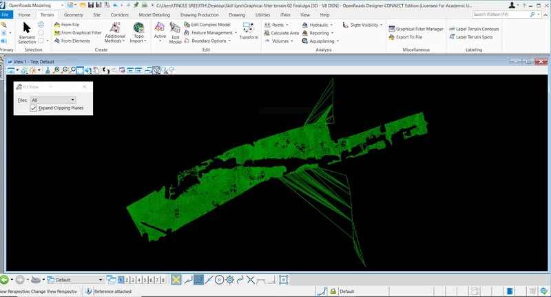
Results
Thus, terrain from Graphics procedure is done.
Q1.5 Terrain creation by elements
The method of terrain creation by elements is described below.
Open ORD=> Training and Examples => Training imperial
Create a new file with 3D seed file=> Name the file => new window pops up => all default => click Ok=>Blank file opens up=> Fit view
Go to Terrain=> create terrain by elements=>Go to element selection tool=>go to element named 'line string'
Go back to Terrain=>Create terrain by elements=> left click and accept it
A small window pops up=>select Feature type and Edge method=>Remove slivers
Also select Feature as Existing triangles and Name ET automatically filled=> Left click and accept it
A new window pops up with a warning message about linking of source=> select yes
File loads and opens up.
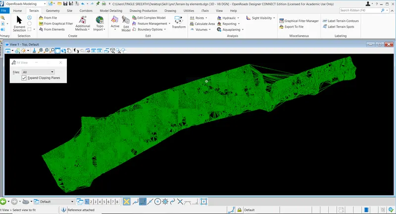
Results
Thus, a new terrain is developed with elements.
Q2. Densely triangulated terrain model without bad spots
Aim and Introduction
The idea of creating a densely triangulated terrain model without bad spots can give more accurate detailing of the ground data. It eases the decision-making process as more details are included in this type of terrain model.
The steps for creating a densely triangulated terrain model without bad spots is described below.
Create a terrain model as described above as per the 'Terrain model creation by elements'
Go to Drawings=> Now go to reference file and turn the level display off to view the triangulation only and select the necessary layers for applying or removing the triangulation data.
Now click on any element and a flyout menu appears on the screen=> click add feature=> a new window appears
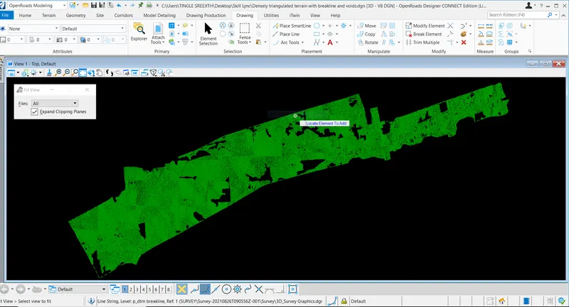
Select Terrain model- ET and Feature type as Void or breakline or Boundary and select the lines accordingly and left click to accept it to load the file. As the new file opens up, the change in triangulation can be visible across the selected objects.
The below image is created by applying Void, Breakline and Boundary features.
Results
Thus, a densely triangulated terrain model without bad spots can be created.
Q3. Exporting terrain model to various files.
Aim and Introduction
ORD drawings can be exported to various other formats to access the drawings for different purposes. This makes the ORD one of the advanced design and modelling software in the world.
The steps for exporting the terrain model is explained below.
Open ORD=>Open the file required to export to different formats=> Open Terrain=> Go to miscellaneous=> select option export to=> select the format required and name the file => save it to a specified location.
Attachment
View Q3DTN, Q3TIN and Q3XML attached
Results
Thus, Terrain file can be exported to different formats.
Q4. Importing the exported file back to a newly created 3D DGN file
Aim and Introduction
The importing option makes it possible to open and work on various file formats through ORD. ORD has diverse range of tools to work specifically on different software.
The steps for Importing an exported file back to a newly created 3D DGN is given below
Open ORD=> Training and Examples => Training imperial
Create a new file with 3D seed file=> Name the file => save the file
Go to workflow 'Survey'=>Home=>Model import/Export=>Create a terrain model from file=> attach file =>file opens up
Go to attributes=> activate the background image as 'Aerial'=> Background image opens and the import is complete.
Results
Thus, a terrain can be imported from an exported file on a newly created 3D DGN.
Note
Go to attachment to see different file formats imported into ORD.
DTM FILE IMPORT 3D DGN
TIN FILE IMPORT 3D DGN
XML FILE IMPORT 3D DGN