Week 2 Challenge
Q1. Workspaces and Worksets
Aim & Introduction.
The Openroads Designer section depicts a detailed description of the software interface, settings, tools, modules, mocrostation models, references, workspace and feature definitions. It also explains the operational procedure and instructions for running the software to develop meaningful designs as per the required standards.
Workspace is basically the client or client related properties and worksets are project specific information or properties. Within a single workspace there can be multiple worksets based on the work or projects. The selection of a specific workspace and workset means the ORD loads all the resources, setting and standards required for the projects. A few examples of worksets are given below.
- National Highway Authority of India (NHAI)
- Public Works Department -State Name
- Ministry of Transport and Communications Oman (MOTC Oman)
- Ashghal Qatar
- Department of Transport Victoria
Examples of Worksets are given below
- National Highway-(highway name or number)
- State Highway-(highway name or number)
- Expressways (Name)
- Freeways (Name)
- District Roads (Name)
The workspace is saved to seed files (by default) location in the C:\program files\Bentley OpenRoads Designer CE\Configuration\workspace\workspace name\workset\workset name\project folder\file name.
Results
The workspace and worksets provides most convenient and flexible way to handle complex projects into a more systematic and workable modules.
Q2. Feature Definitions
Aim & Introduction.
Feature Definitions are pre-defined templates or tools or commands which can be used for carrying out specific geometric design tasks in customer's dgn files. Also, the Feature definitions can be modified once it is copied into an active DGN file. Different types of feature definitions are listed below.
- Alignments
- Terrain models
- Corridors
- Linear templates
- Surface templates
- Civil Cells
- Superelevation
- Cant
- Linear Geometry
- 3D linear elements
- Points
- Referenced models
- Sight visibility sections
- Aquaplanning
- Conic slope
- Site layout.
Results
The Feature Definitions has made the ORD geometric design easier with the pre-defined templates.
Q3. Creating DGN file with 2D Imperial Seed and 3D Imperial Seed
Aim & Introduction
Creating a DGN from 2D Imperial Seed and 3D Imperial seed is the basic process during the initial stages of ORD based modelling. This helps the designer to work with 2D model template and 3D model template to develop the final design files.
The DGN from 2D Imperial Seed is attached below.
The steps involved in the process is listed below.
Open ORD
Go to => Training and Examples=>Training Imperial
Go to => New file=>select DGN file(browse)
Go to =>seed file=>select Seed 2D=> name the file => Open the file
Go to => File in software interface=> settings=> File=>Design File settings=> make necessary changes in units and save it
Go to=> Save settings=> save file
Finally save the file in required folder.
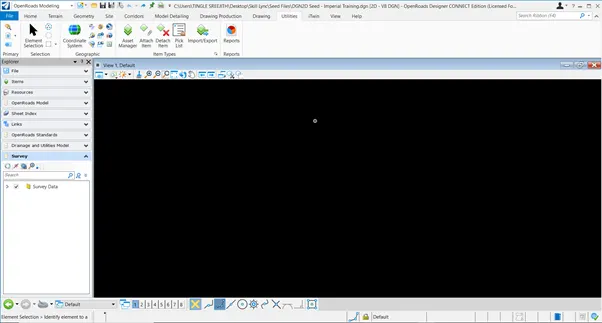
The DGN from 3D Imperial seed is attached below
The steps involved in the process is listed below.
Open ORD
Go to => Training and Examples=>Training Imperial
Go to => New file=>select DGN file( browse)
Go to =>seed file=>select Seed 3D=> name the file => Open the file
Go to => File in sofware interface=> settings=> File=>Design File settings=> make necessary changes in units and save it
Go to=> Save settings=> save file
Finally save the file in required folder.
Results.
Through the above-mentioned steps, DGN from 2D Imperial seed and 3D Imperial seed can be generated which in fact helps the ORD design process to develop more detailed designs.
Q4. Setting up Geographic coordinate system.
Aim and Introduction.
The process of setting the specific geographic coordinate system helps the designer to develop more accurate and detailed models based on the ground reality.
The steps involved in the process is listed below
Open the 3D seed file
Workflow openroads modelling
Go to =>Utilities=> coordinate system
Go to => Library=> browse coordinate system TX83-NCF-NAD83(US foot)
Go to => Save setting and save file
Go to =>Attributes=>Background map=> Arial=>Load file
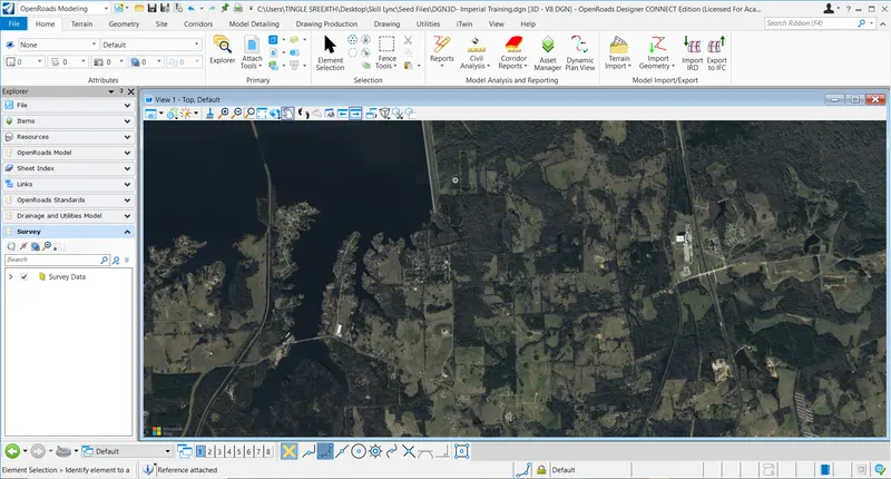
Arial map opens up
Results
Thus, the aerial image of the selected location opens up for further design process.
Q5: Attaching Survey details to 2D Imperial Seed
Aim & Introduction
Superimposing the survey data on the arial image will improve the accuracy of the ORD modelling and to great extent the process will eliminate any inaccurate data in the initial stages of the design process.
The Steps involved in the process is listed below.
Open ORD=> Open the 2D seed file
Go to=> Utilities=> Coordinate systems=>browse TX-83-NCF-NAD83 (US foot)
Save settings and Save file
Go to attributes=>Background map=> activate 'Arial' Image=> Arial image opens up
Go to=>Drawings=>attach tools=>attach references=>browse refence file from Survey folder
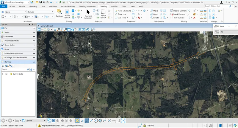
Window pops up=> check coincident world, model, live nesting, layer depth and give logical name to the file, finally load the reference file=> click fit view to see the attached reference file data.
Results
Thus, the Survey data reference file can be attached to the arial image on a 2D seed file.