Week 5 Challenge
Q1. Creating Horizontal Geometry.
Aim & Introduction
There are various methods to draw horizontal geometry in ORD and the different tools are explained in this section. Also, the procedure for the same is explained below.
Procedure
Open ORD=> Training & Examples=> Training Imperial
Browse 2D seed file=> Name the file=> Blank window loads up=> Go to Geometry=> Standards=> Feature Definition
New window opens up=> select Feature Definition=>Alignment=> Geometric Base line
Go to Line tools=>Line between points=> small window pops up=> assign FD as Geom base line => Draw a line or multiple lines ( Note : lines can be drawn even without assigning FD).
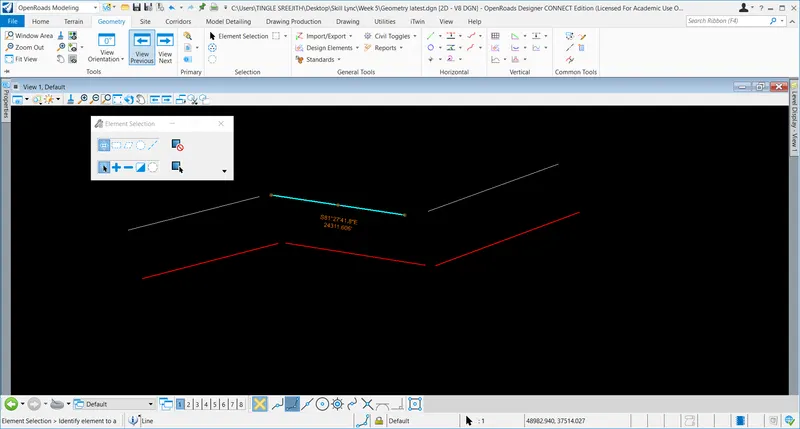
Method 2 : drawing line between Arcs
Go to line tool=> select Arc=> Draw one or 2 arcs=> Go to lines=> simple line to element => assign FD Geom Baseline=>
Select the element=> locate starting point and end points and draw the line.
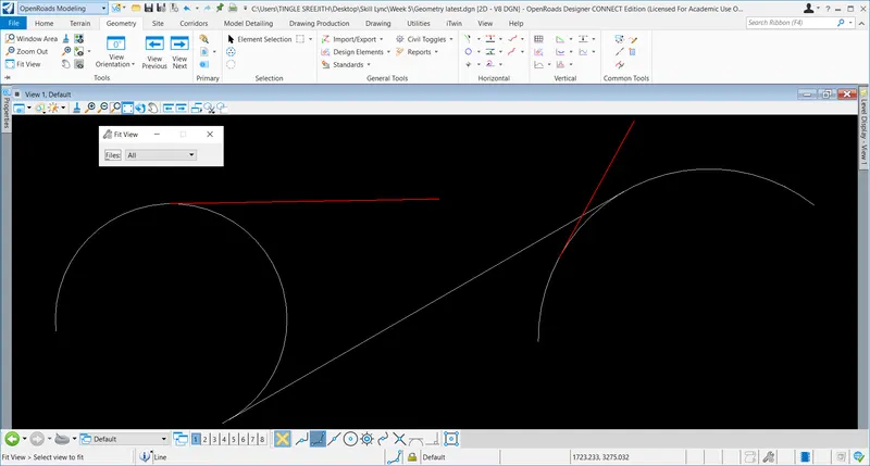
Method 3 Line from element
Go to line tools=> draw a complex PI=> go to draw a line from element=> go to line from element => select element=> select start point and end point and draw the line ( Note : FD can be assigned if needed)
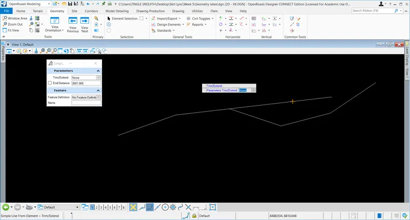
Method 4: Drawing arc between points
Go to line tools=> Draw 2 or 3 simple lines without FD=> No go to Arc=> Arc between points=>select the methods, offset etc=> draw arc between lines=> use civil handles to make it smooth=> Go to standards=>set feature definition=> select arcs=> arcs can be visible in different colours as the FD is assigned.
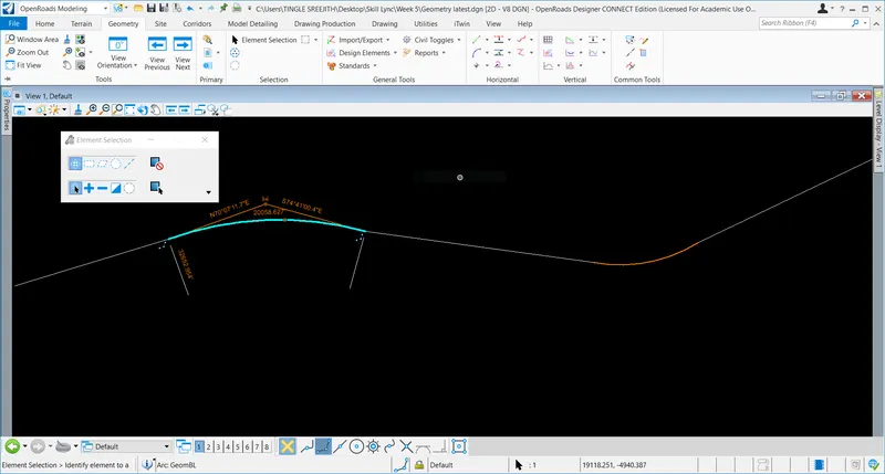
In order to draw arc at the end of elements=> go arcs=> select arc to element => select offset and parameters like radius and through points. FD can be assigned if needed.
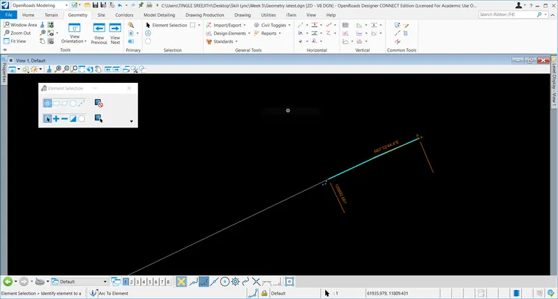
Results
Thus, lines and arcs can be created using various methods.
Q2 : Creating Offsets
Aim and Introduction
There are various methods for drawing horizontal geometry in ORD. This section explains how horizontal geometry properties can be modified using different alignment tools.
Procedure
The procedure for creating Horizontal geometry and modification details are given below.
Open ORD => Training and Examples=> Training Imperial
Select a 2D seed file and create a new dgn file=> file opens up
Go to Geometry=> lines=>draw a box with 500' side length
Go to lines=> Chamfer between lines and draw chamfer at two ends and trim both ends
Go to modify=>insert fillet and insert two fillets at the other two corners and trim off the excess part
Go to complex geometry=> complex by element method=>window appears=> select method as automatic=> lines became a complex element.
Now go to offsets and tapers and offsets the members 5' inside and 20' outside and trim to the line to extend lines
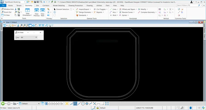
Results
Thus, Offsets for the shape has been created.
Q3. Create any point featured element along the outmost shape by point tools.
Aim and Introduction
Point featured elements can be used by various methods in ORD and methods are described below.
Procedure
Open ORD=>T&E=>TE=> create a new file with seed 2 D file
File opens up=> attach terrain model by reference attach model
Give surface to grid ratio 1:1.00012=> set coordinate system
Go to attributes and turn on the aerial imagery=> go to line and draw a line between any points
Now go to points=> select equal space between points=> window appears=> select placement mode, spacing intervals, rotation and offsets. Also give elevation as zero and rotation as none=> select Fd as Utility poles=> Now go to properties and turn off the contours=> now the equally placed points will be visible.
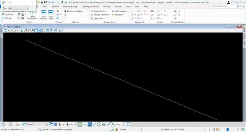
Now again turn on the Aerial view =>go to offsets and tapers=> select single offset entire element=> give offset of 15 and select FD as road shoulder draw line and => now turn off the aerial image, a parallel line can be seen it the model.
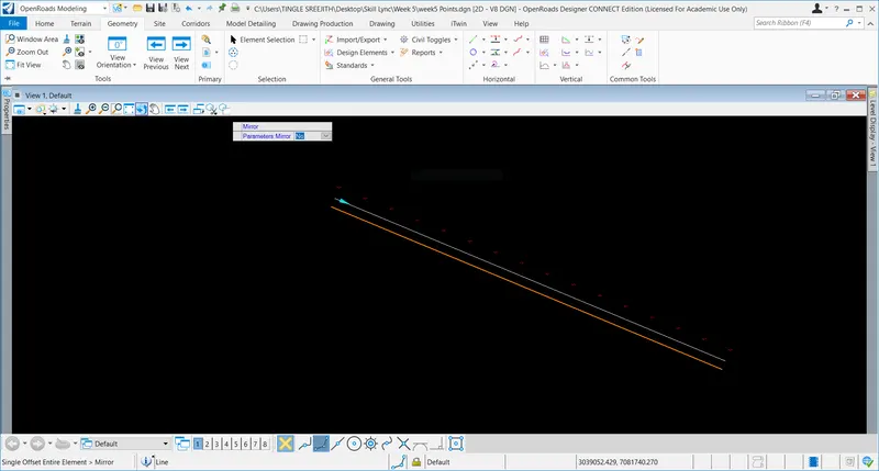
Note that the newly drawn line is linked to previous line and any changes done in the parent line will affect the newly drawn line.
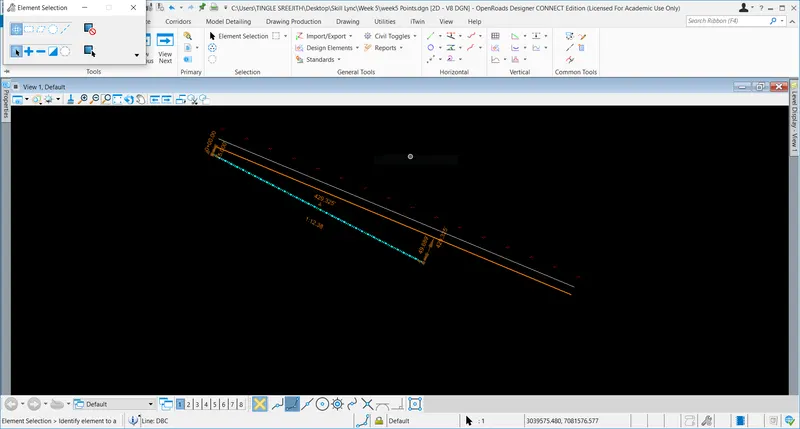
Now again go to offsets and tapers=> select variable offset and tapers and select offset at start and end, also select FD as ditch bottom centre.
Note that any changes made in this line will not affect the parent line. But any changes in the parent line will again affect the newly drawn line.
Results
Thus, variable offset line can be drawn.