Week 4 Challenge
Week 3 Q 1.2 Terrain Creation by ASCII
Aim & Introduction.
There are many methods available in ORD for the Terrain Creation and Terrain creation by ASCII is one of the easiest methods if right data is available. Together with ASCII method and filters, terrain can be created more accurately.
Procedure
The method of creating terrain with ASCII file and filters is described below.
Open ORD=>Training and Examples=>Training Imperial
Open a new file=> Browse 3D seed file=>Save the file in a specified location ( no reference attachment required)
Go to Survey folder =>attach either Text, CSV or Xlsx file=> a new window opens up=> Go to Text import option=>another window pops up=> check the data and select the First line to import
Go to last line to import=>EOF
Select Decimal separator=> select comma=> click next=> go to delimited separators
Select Feature type => Spots, also select Feature symbology: point\existing\terrain\eterrain
Go down and select column delimiter => click comma=> all data segregated into different columns
Now go all column header and change the name according to the data ie: Northing, Easting, Elevation and Description
Click next and select the Coordinate system=> Finish (option pops up for saving the Text import wizard setting file)
Go back to the previous main window=> FD- Existing terrain/existing triangles=>Remove slivers=> ‘import terrain only ‘=>import=> fit view and rotate view to see the triangulation.
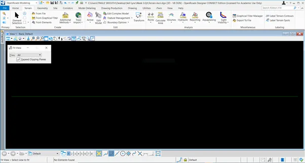
Since the data is not accurate the terrain is not properly visible, and the triangulation happened in one end of the terrain model with lots of zero elevation data triangulation. So, the profile can be refined with ASCII and filters and the procedure for using the ASCII filters is explained below.
Go to Terrain creation by ASCII => go to Survey folder => attach the text file PNEZ.text
Click done=> new window opens up=> go to text import settings wizard=>new window opens up (Before this closely watch the actual data for zero elevation points which needs to be avoided, in this case the zero elevation points are described as 'Default ' in the file.
Go to column (in text import wizard settings) => select Feature type as Spot and Select the Feature symbology as Point/existing/terrain/e-terrain
Next tick comma in the box (and remove every tick in other boxes)
Now go to the data set and click on skip and change it as Northing, Easting and Elevation respectively
Next go to filters just below the column and make changes 'Exclude', 'Delimited', 'Lines including text', 'Default', 'spot' and 'points/existing / terrain/eterrain.
Now select 'Comma' and again select Northing, Easting and Elevation => click next=> finish (save or overwrite)
Go to main window=> Change Feature Definition=> Terrain/existing/existing contours (everything else remains same in the window)
Now change the name of the file PNEZD to Clean Terrain=> click import
New terrain opens up with multiple terrains in it. The blue shaded terrain with the name Clear Terrain and Green coloured terrain with name PNEZ.
Now click on the PNEZD terrain and flyout menu appear=> properties=> turn off all triangulation and all green goes off.
Next click the blue terrain => flyout menu=>properties=>turn on triangulation and turn off contours Major and Minor for the blue shaded terrain.
Finally, a clean terrain opens up without any zero elevations in it.
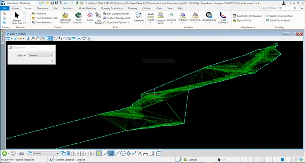
Results
Thus, terrain with ASCII and filters has been created with refined properties.
Week 3 Q1.4 Create terrain by Text interpolation.
Aim & Introduction
Terrain by text interpolation is one of the methods to create the terrain and it can be done by creating multiple filters on the 3d graphical data.
Procedure
The method of creating terrain by text interpolation is given below.
Open ORD=>Training and Examples=> Training imperial
Open roads modelling=> Terrain
Open a new file => Browse the 3D seed =>save file in the preferred location and blank file opens up
Go to Home and attach the 3d Graphics file and file opens up=> go to level display menu and turn off the display=>and go to the level display menu and tun on only Edtm contour Major and Minor only=> Just keep the cursor on the contours to see the properties of the contours.
Go back to create terrain by ‘additional method’=> click terrain by text interpolation method=> new window pops up=>click terrain filter manager=> new window pops up=>Create a filter group named ‘Linear Filter’
Go to Filter and create Filters named ‘Contour ‘(Feature type contour) with description ‘liner feature’ and Text with description ‘contour elevations’ - Feature type contour=> now go to edit => a new window pops up=> select element type=>Text=> add => and finish
Again, go back to edit filter=>select element type> select line string=>add=>Finish
Now go to the Terrain Filter Manager=>Filter group (linear filter) =>Properties=>drop down menu=>select filter as Contours =>
Again, go back to Terrain Filter manager=>properties =>drop down menu=> select filter as Text
Go back to terrain by text interpolation and the window pops up=> go to ‘Text filter and select Text’
Select ‘linear Filter Feature’ as Linear filter’ and tick the Text as spot level=> Now left click and accept it
Triangulation opens up with white colour=> color can be changed by going into flyout menu=>open properties=>select feature definition =>click Terrain=> pick existing contours.
Q2. Terrain model Editing
Aim and Introduction.
There are many editing tools available in ORD and terrain modification tools are most convenient tools to edit the models in a quick way.
Procedure
The major methods of editing models and procedures are described below.
Open ORD=> Training and Examples => Training imperial
Create a new file with 3D seed file=>Name the file and window opens up
Go to create terrain from file method and browse any .TIN file from the survey folder
Rotate the view to see if there is any unnecessary data=> fit view=> Go to explorer=>properties=> Max edge length as 500
Go to Editing tools=>edit model=> Click => new window opens up with 7 types of editing tools
Tool 1(Delete vertex) => go to the model and place the mouse around any vertex it will be highlighted, and it can be deleted. Further the triangulation will be adjusted accordingly.
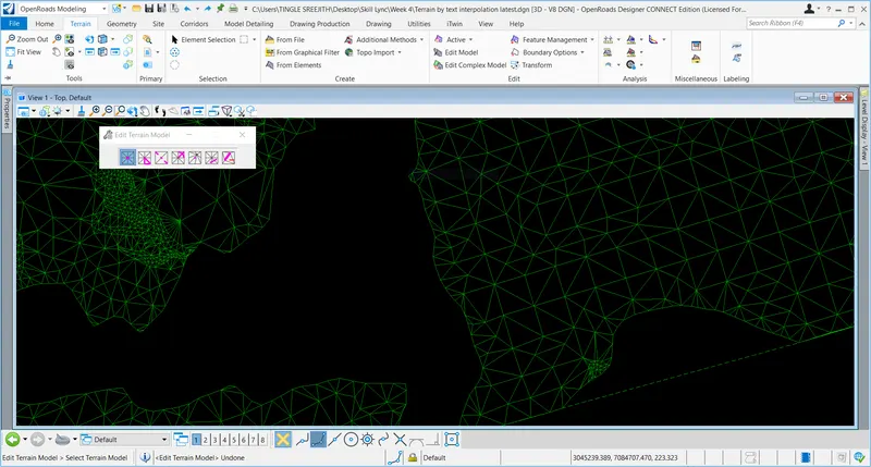
Tool 2(Delete Edge triangles)=> click on the tool => select the model=> place the mouse near the edge triangulation and the triagles will be highlighted=> left click => triangle sides will be deleted.
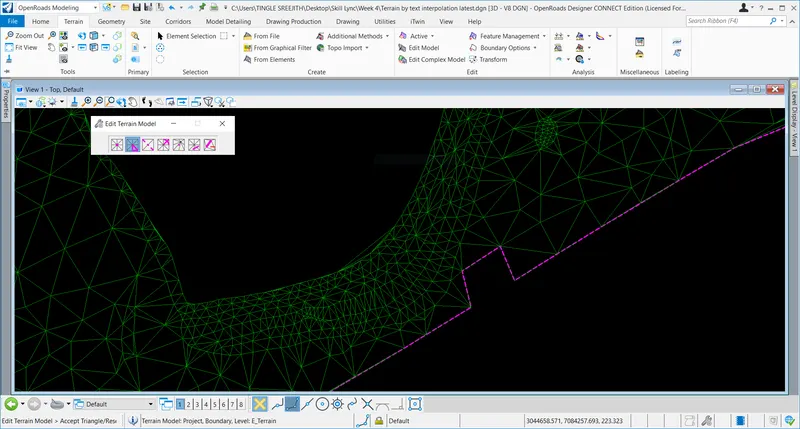
Tool3 (Swap line) => click on the tool=> select the model => place the cursor on any triangle sides=>side will be highlighted=> left click=> line will be automatically swapped to opposite direction.
Tool4(Insert vertex) => click on the tool=> select the model=> place the cursor on any triangulation=> triangle will be highlighted=> left click=> a new vertex will be inserted in the exact position of the cursor.
Tool5(Move vertex) => click on the tool=> select model=> place the cursor on any vertex=> click and move it along the cursor movement
Tool 6(Delete triangle by line) => click on the tool> select model=> place the cursor outside the model and click and draw a line => sides of the triangles highlighted along the line can be deleted.
Tool 6(Delete Feature) => click on the tool=> select model=> go to any specific feature in the model=> it can be deleted.
Results
Thus, terrain can be edited with different tools.
Q.3. Annotate Contours with Labels.
Aim & Introduction
Annotation is an important part of the drawing production as it gives more detailed description of the produced drawing and there are different types of annotations based on the requirement.
Procedure
The step by step process of contour annotation and spot elevation annotation is described below.
Open ORD=> Training and Examples => Training Imperial
Browse 3D seed file => Name the file and window opens up=> go to Create terrain from file=> import the .TIN file
Click fit view=> go to properties=> turn off all features=> turn on only Edtm Contours major and Edtm Contours Minor
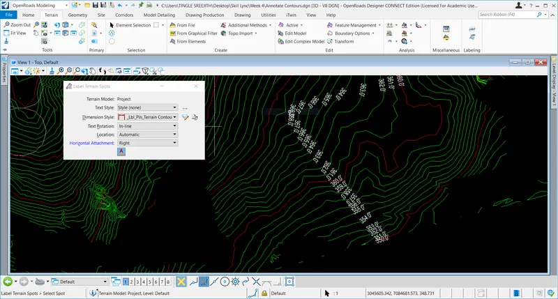
Go to labelling=> click labelling=>new window opens up
Select terrain model=>Annotation=> all contours=>Text alignment=>Follow line
Pick Dimension style=> Terrain contour elevations
Now go to drawing and draw a line with mouse and all elevation details will be displayed on the drawing.
Results
Thus, contour elevation labelling & annotation is done.
Spot level labelling
Procedure
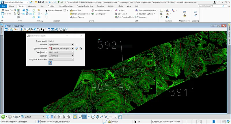
Go to same drawing described above and click Spot labelling=> Window opens up=>select the terrain
Pick dimension style=> spot elevations
Now go to the drawing and keep the cursor in a spot and draw a line, the spot elevation will be displayed in the drawing.
Results
Thus, spot elevation labelling is done.
Q4. Contour Editing
Aim & Introduction.
The terrain modification tools make the ORD much flexible than any other software so, by editing the contours the terrain can be used for more customised way as per the requirement of the designer/customer.
Procedure
The steps for editing the contours is described below.
Open ORD=> Training and Examples=> Training Imperial
Browse a new file with 3D seed file=> Name the file=> Window Opens up
Go to Terrain=> attach .TIN file through 'Create terrain from file method'=>click fit view to see the file
Go to level display tool and turn off all layers except contour Major and Minor
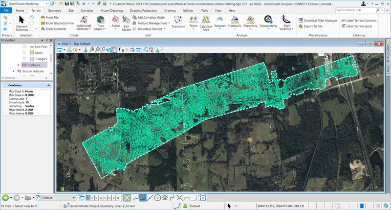
Click terrain model=> properties=>Select Elements (select terrain) =>Calculated features=> scroll down to contours => click=>select contour major and minor intervals
Results
Thus, contour intervals can be modified.