Week 7 Challenge
- Setup model for RC building design and based on following parameters for cover
|
MEMBERS |
IN CONTACT WITH GROUND |
ABOVE GROUND |
|
Column |
50mm |
40mm |
|
Beam |
30mm |
25mm |
|
Slab |
30mm |
25mm |
|
Pilecap |
75mm |
|
|
Foundation |
50mm |
AIM: To set up a model for RC building design and based on given parameters.
Procedure:
Step1: Open the software and take a new file.
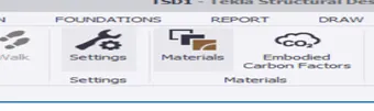
Step2: After opening a new file to set the material of the members of the model, go to the home tab in Ribbon Bar and click on Materials.
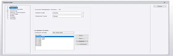
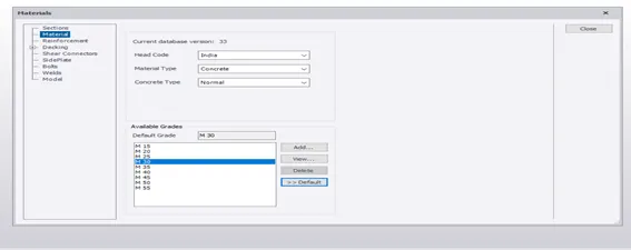
Step3: Then a window like this will appear, click on materials in the list then change the steel property to fe410 and concrete grade as M30 by clicking on default. Finally, click on close.
Step4: To create properties sets go to the home tab and click on manage properties.
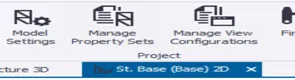
Step5: Then create new sets with given covers as given then click on ok finally.
|
MEMBERS |
IN CONTACT WITH GROUND |
ABOVE GROUND |
|
Column |
50mm |
40mm |
|
Beam |
30mm |
25mm |
|
Slab |
30mm |
25mm |
|
Pilecap |
75mm |
|
|
Foundation |
50mm |

Result: By following this procedure we can create materials of desired properties.
2. Model grids as per the attachment 2,2.1 and 2.2
AIM: To Model grids as per the given attachment.
Procedure:
Step1: First click on the model tab in Ribbon Bar then go to construction levels in the levels panel.

Step2: Then a window will appear like this. Next click on insert options to create new levels.
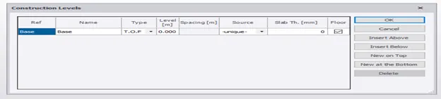
Step3: After creating the levels like this will appear. Finally, click on ok.
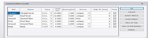
Step4: In the project workspace created levels will appear like this.
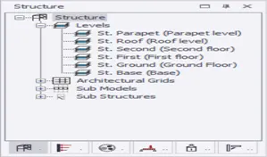
Step5: Then go to grids in the model tab various options will be there by using them we can create grids with specified distances.
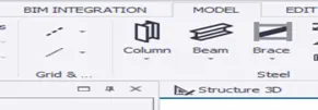
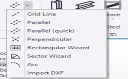
Step6: Then created grids will appear like this.
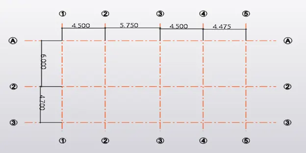
Result: By following this procedure we can create the grid lines with the required dimensions.
- Study the layout and write a summary for general arrangement of the structure
AIM: To Study the layout and write a summary for the general arrangement of the structure.
Procedure:
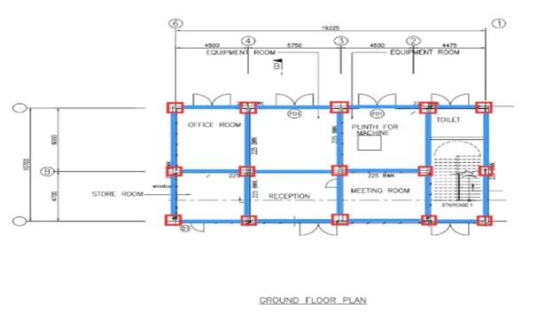
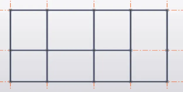
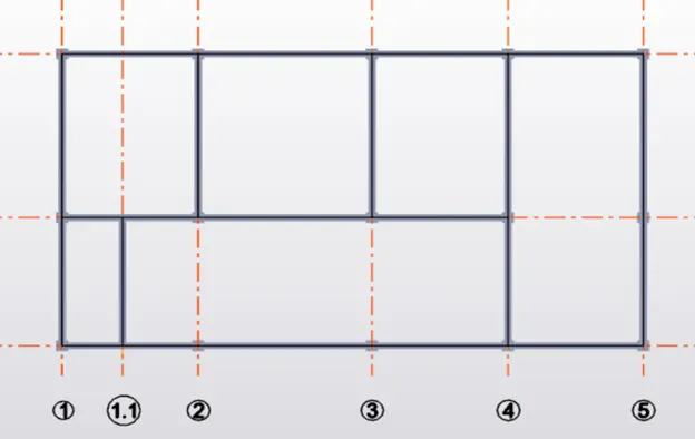
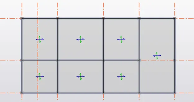
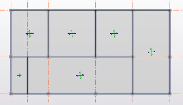
After opening the plan then first we must go through with the plan next, we have to see the arrangement of the grid and check the distances between them. Later we have to mark the column placement and beam placements.
Ground Floor
First & Second Floor
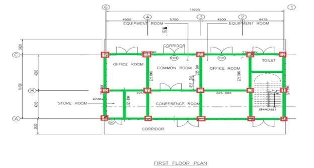
In this Sketch, we had done a general arrangement of beam and column by assuming the grid intersections as column Placement points. If there are any issues while designing, then we can change Positions or material etc.,
Result: By resolving all the issues then we can proceed with the further modeling of the project.
- Model RC columns, beams, and slabs as per your general arrangement
AIM: To Model RC columns, beams, and slabs as per your general arrangement.
Procedure:
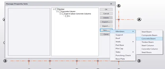
Step1: In home tab, we can create materials using manage property sets.
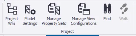
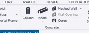
Step2: Create a concrete column named C1. And assign them in the base level at grid intersections according to the plan.
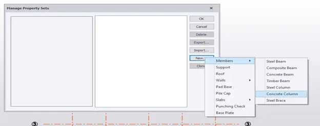
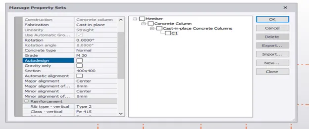
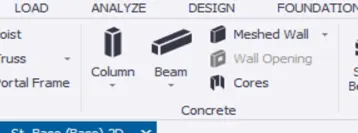
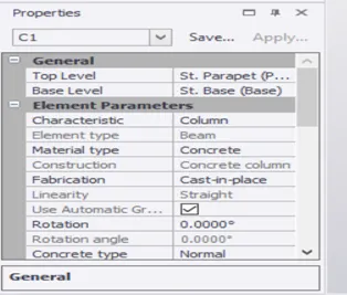
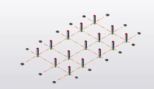
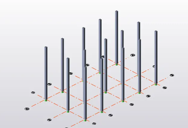
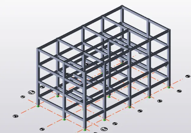
Step3: Create new material of concrete beam and name as B1 and assign beams in the ground, first & second, roof levels as per the plan given Between columns.
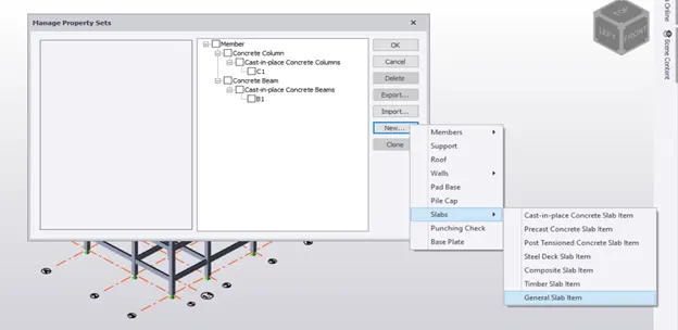
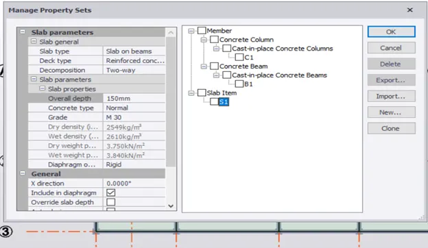
Step4: Create a new material for slab and name as S1 and assign the property as two-way slab and assign the slab in Ground, first & roof levels.
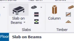
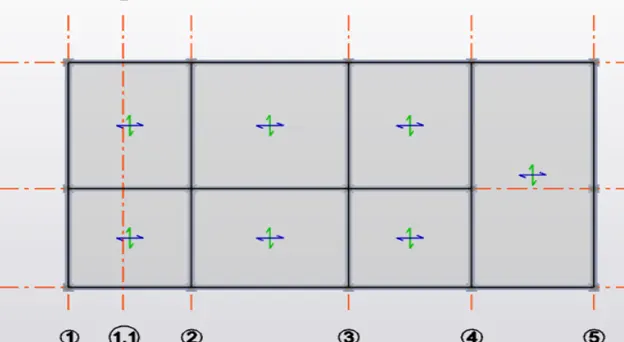
Result: By following the above procedure we had Model RC columns, beams, and slabs as per your general arrangement.
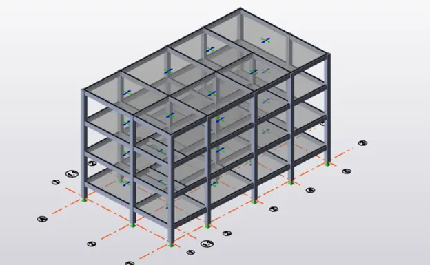
The structure will look like this after assigning all properties like columns, beams, and slabs according to the plan given in the attachment.