Week 4 Challenge
1. ANS.
AIM: To Calculate and applying dead load in design report based on IS code on the model.
- Finishes of 50mm
- Slab as per design
- Brick wall 150mm thickness
- Roofing load based on purlin size
- Ceiling loading 0f 0.3KN per sq m
DEAD LOAD CALCULATION:
Slab load = calculated by software itself.
Finishes loading = thickness x unit weight of concrete
0.05m x 24 kN/m3 = 1.2 kN/m2
Brick wall thickness= 150mm
= 0.15m
Unit weight of brick = 20kN/m3
Floor height (GF to FF) = 5.2m
Floor height (FF to Roof) = 6.8m
Brick wall loading @ GF to FF = 0.15 x 20 x 5.2
= 15.6 kN/m
Brick wall loading @ FF to Roof = 0.15 x 20 x 6.8
= 20.4 kN/m
Roofing load based on purlin size = 1.5 kN/m2
Procedure:
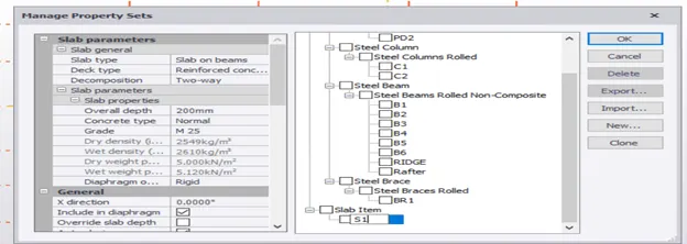
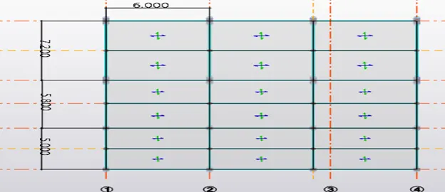
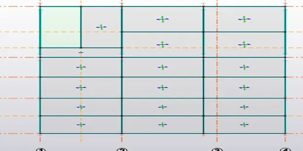
Step1: After calculation of dead loads which are to be applied to the model. Open the previous file and create slab property in property sets. Then create a slab in GF and FF as required. Just see the below images for reference.
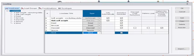
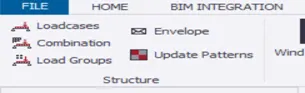
Step2: Now coming to the Load application go to the Load tab and click on load cases in the structure panel to create load cases.
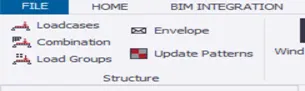
Then like this window will display add new load cases required to the existing loads. And click on ok.
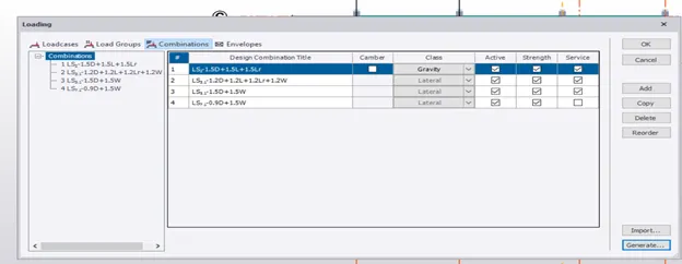
Next click on Combinations to create load combinations.
Then like this window will display. For Load combinations to be created or generated using generate option.
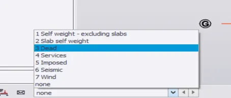
Step3: Then click on the loading list at the bottom left corner and select Dead from the list to apply dead load by opening the required View.
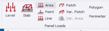
Step4: Go to the Load tab and select area load to apply a finishes load of 1.2kN/m2.
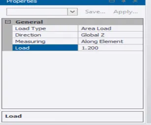
Then go to Properties and change the load as 1.2
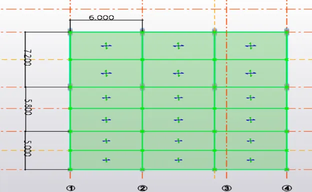
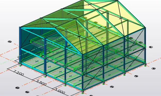
Apply the area load to all the floors and it will appear like the below images in 2D and 3D. And also apply a Celling load of 0.3.
Step5: Next to apply Brick wall loading From GF to FF. We have to apply a Full UDL of 15.6 which had been calculated at the starting by changing in properties on members.
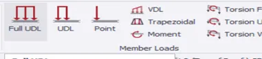
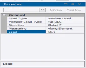
After application, it will look like this.
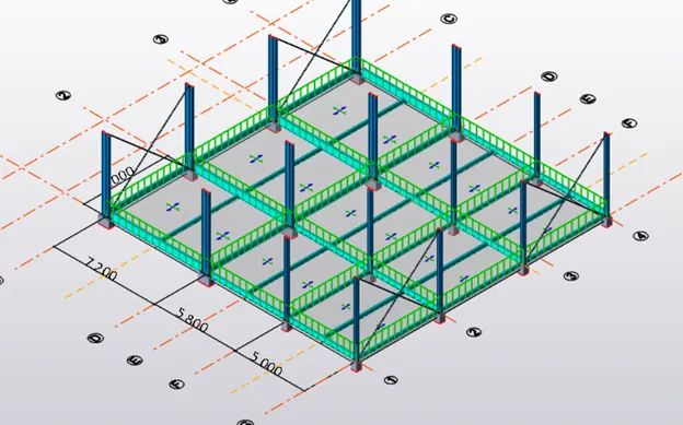
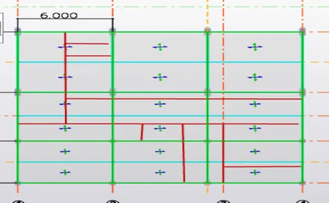
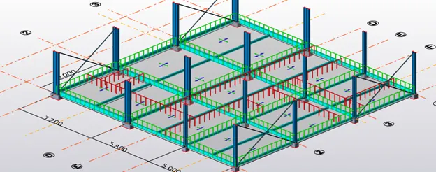
Step 6: Next we have to apply Brick wall loading of 15.6 on the Brick wall where it had been constructed according to the Sketch. Be careful while applying this line load it should not be placed beyond the panel i.e., it should be within the panel. Validate after application to check whether the applied load is correct or not.
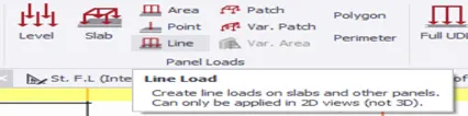
After application, it will appear like this in plan view.
it will appear like this in 3D view.
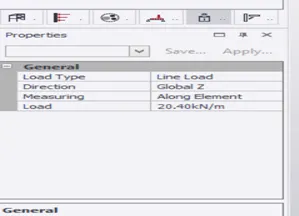
Step7: Next to apply Brick wall loading From FF to Roof. We have to apply the Full UDL of 20.4 which had been calculated at the starting by changing in properties on members.
After application, it will look like this.
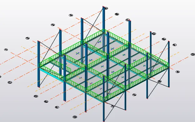
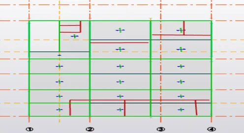
Step8: Next we have to apply Brick wall loading of 20.4 on the Brick wall where it had been constructed according to the Sketch. Be careful while applying this line load it should not be placed beyond the panel i.e., it should be within the panel. Validate after application to check whether the applied load is correct or not. After application, it will appear like this in plan view.
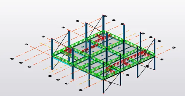
it will appear like this in 3D view.
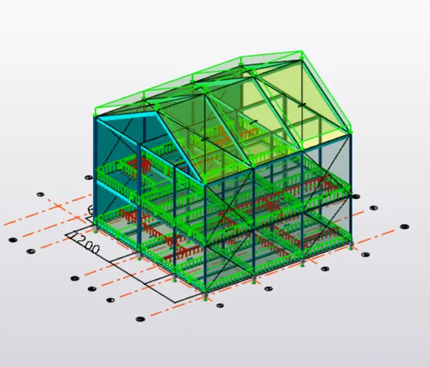
RESULT: After calculation and application of dead load by following the above procedure and with reference to the IS 875(Part1) you will get this result.
2.ANS.
AIM: To Calculate live load in design report based on IS code and applying live load on the model
- Assume the loading based on IS 875
- Roof loading
- Consider equipment loading as 5KN per sq m
Considerations:
Live Loads @ GF:
Stair case = 5kN/m
Workshop = 5 kN/m (considering light machinary)
Corridor = 5 kN/m
Meeting Room = 5kN/m
Storre room = 5kN/m
Toilet = 2 kN/m
Canteen = 3kN/m
Office = 3 kN/m
Conference room = 5kN/m
Equipment Room = kN/m
Live Loads @ FF:
Stair case = 5kN/m
Rest room = 2 kN/m
Meeting Room = 5kN/m
Administration room = 5kN/m
Office = 3 kN/m
Toilet = 2 kN/m
Live Load @ roof:
From IS 875(Part2) table-2 for sloped roofs we have to consider 0.75kN/m2 for every degree rise in slope over 10 degrees we have to reduce 0.02kN/m2. For our ease and conservative purpose, we will take 0.75kN/m2.
Procedure:
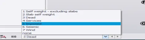
Step1: Then click on loading list at bottom left corner and select Imposed from the list to apply dead load by opening the required View.
Apply the area load by comparing the sketch and apply the appropriate load at the appropriate area panel. Finally, after application, it will appear like the below images for both the GF & FF.
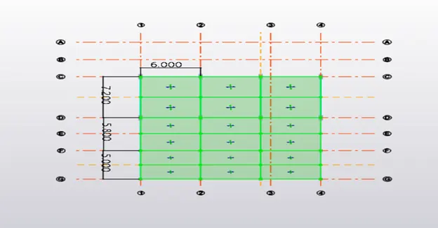
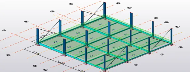
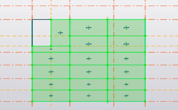
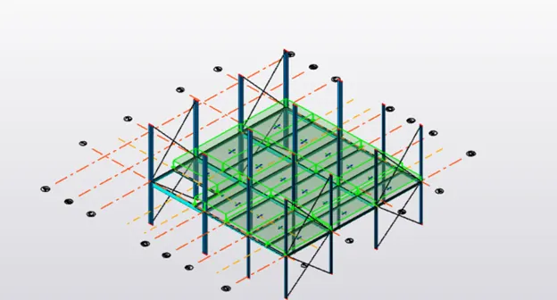
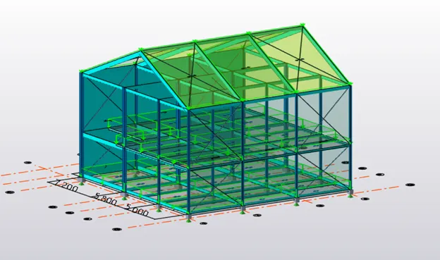
RESULT: After application of live load to the model in GF, FF & Roof with the reference of the sketch and with reference to the IS 875(Part1) it will be appeared like this in 3D View.
3.ANS.
AIM: To generating a calculation for 5T crane loading based on the following inputs
- Centre to Centre of wheel = 10m
- Weight of crab = 40 KN
- Number of wheels = 4
- Wheelbase = 2m
Procedure:
Calculation:
Crane capacity = 50kN
Self-weight of crane girder excluding trolly = 40kN
Weight of the trolly or crab = 10kN
Approximate minimum approach of hook to girder = 1m
c/c distance between columns = 5.5m
c/c distance between wheels = 10m
Self weight of rails = 300N/m = 0.3kN/m
Yield stress of steel = 250N/m2 = 0.25kN/m2
Wheel base = 2m
MAXIMUM WHEEL LOAD:
Max concentrated load on crane = 50+10 = 60kN
Self weight of the crane will act as UDL = 40/10 = 4kN/m
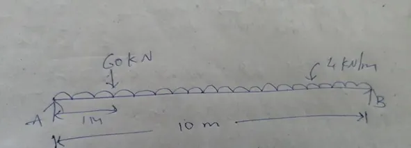
Consider moment about B:
RA x 10 = (60x9)+(4x10/2x10) = 540+200 = 740
RA = 74kN
We know ∑Y = 0
RA + RB = 60+ 4x10 = 100
RB = 100-74 = 26kN
The load from the girder is distributed equally on two wheels. So, Max wheel load = 74/2= 37kN
MAXIMUM BENDING MOMENT:
Assume the self weight of gantry girder as 1.5kN/m
Total Dead Load = Self weight of rail + self weight of gantry girder
= 300+1500 = 1800N/m
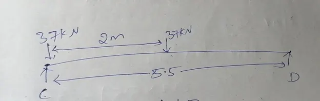
Consider moment @ D
RC x5.5 = (37x4.25)+(37x2.25)
RC = 43.72kN
We know ∑Y = 0
RC + RD = 37+37
RD = 74 – 43.72 = 30.27kN
Bending Moment under wheel due to live lode = RD x2 = 30.27x2 = 60.54kNm
Bending moment due to impact = 10/100 x 60.54 (10% increase due to MOT)
= 6.054kNm
Total Bending Moment due to live load and Impact load = 60.54+6.054 = 66.594kNm
Bending moment due to Dead Load = 1.8x5.5x5.5/2 = 27.225kNm
Maximum Bending Moment = 66.594 + 27.225 = 93.819kNm
MAXIMUM SHEAR FORCE:
Shear Force
RCx5.5-(37x5.5)-(37x2.5) = 0
RC = 5.381kN
Max shear force due to wheel load = 5.381kN
LATERAL FORCES:
Lateral forces traverse to rails
= 5% of weight of crab and weight lifted
= (5/100) (40+10)= 2.5kN
Lateral force on each side wheel, F1 = 2.5/2 = 1.25kN
Maximum horizontal reaction due to lateral force @ C
= Lateral force x Reaction @c due to vertical load/Max wheel load due to vertical load
= 1.25x43.72/37 = 1.44kN
At D
2.5-1.44 = 1.06kN
Bending Moment due to lateral load = 1.25/37 x 5.31 = 0.179kNm
RESULT:
By calculating the crane loads by following the above procedure we got the following Results:
RA = 74kN
RB = 26kN
RC = 43.72kN
RD = 30.27kN
Maximum Bending Moment = 98.819kNm
Maximum Shear Forced due to wheel load = 5.81kN
Lateral force on each side wheel, F1 = 1.25kN
Bending Moment due to lateral load by proportion = 0.179kNm