Week 1 Challenge
1. Answer:
AIM: To tell about the access and the usage of the following:
- Project Workspace
- Scene Content
- Create two scene views
- Loading drop list
- Properties windows
Procedure:
(a) Project Workspace: This is the main part which we are using to control all the things in for the project. We can see this which is shown in the below figure on the left side of the project window.
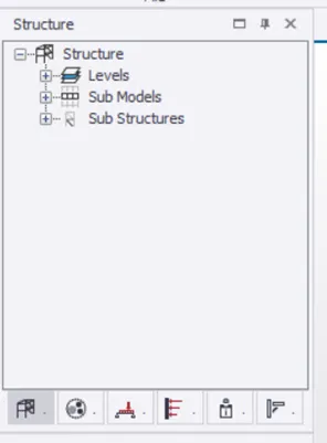
- Structure - For opening scene views.
- Groups - Manage groups for design and RC detailing.
- Loading- List of load cases and combinations in a hierarchy way.
- Wind Model - For wind design for a model.
- Status - This displays the status of the modeling.
- Connections - For viewing and designing steel connections.
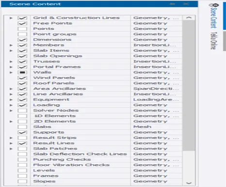
(b) Scene Content: This can be present at the right edge of the Project window. By using this window you can hide or unhide the things in the scene view and finally, it is called a view control window.
(C) Creation of two scene views:
Step 1: First open the software by double-click.
Step2: After opening click on new.
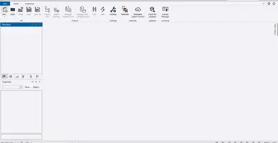
Step3: After opening the new file the window is visible like this.
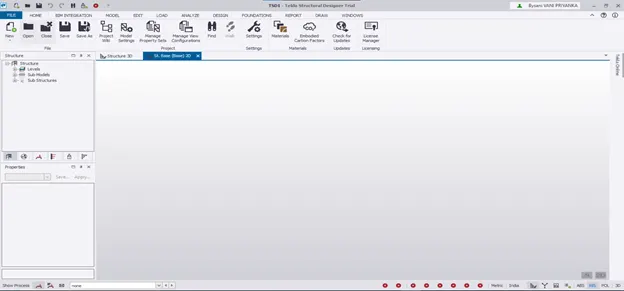
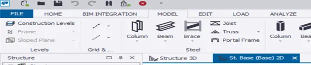
Step4: Then click on the model tab in Ribbon Bar. Their click on construction levels.
Step5: Then a window like this will appear, then create new views by clicking on insert below or insert above options.
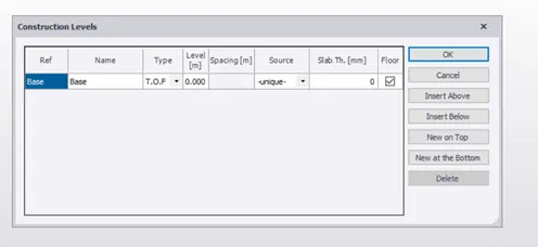
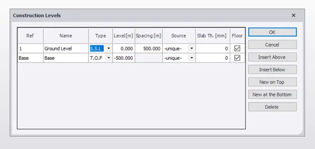
Step6: Create the levels as required and finally click on ok.
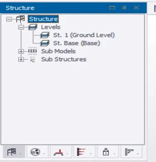
Step7: we can see the created scene views in the project workspace.
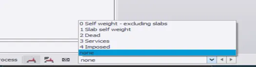
(D) Loading drop list: In the loading drop list we can access all the loadings of our model and we can see this at the bottom left edge of the project window.
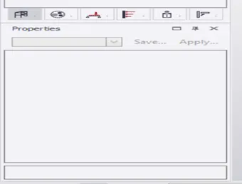
(e) Properties windows: By using this properties window we can edit or check the properties of the model. This window can be seen on the left side of the project window which is below the project workspace.
Result: In this way, we can access all the content in User Interface.
2. Answer:
Aim: Creating a new file in TSD and set up the settings for a steel building to have member grade FE410 and concrete grade of M30 as per IS codes. The covers for the members to be as per the following input:
|
MEMBERS |
IN CONTACT WITH GROUND |
ABOVE GROUND |
|
Column |
50mm |
40mm |
|
Slab |
30mm |
25mm |
|
Pile cap |
75mm |
|
|
Foundation |
50mm |
Procedure:
Step1: Open the software and take a new file.
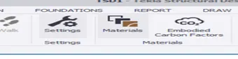
Step2: After opening a new file to set the material of the members of the model, go to the home tab in Ribbon Bar and click on Materials.
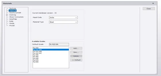
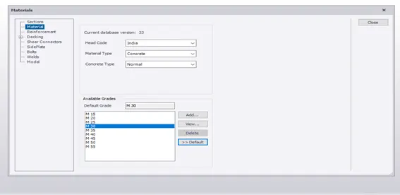
Step3: Then a window like this will appear, click on materials in the list then change the steel property to fe410 and concrete grade as M30 by clicking on default. Finally, click on close.
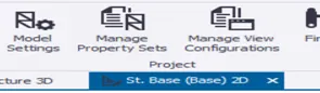
Step4: To create properties sets go to the home tab and click on manage properties.
Step5: Then create new sets with covers as given then click on ok finally.
|
MEMBERS |
IN CONTACT WITH GROUND |
ABOVE GROUND |
|
Column |
50mm |
40mm |
|
Slab |
30mm |
25mm |
|
Pile cap |
75mm |
|
|
Foundation |
50mm |
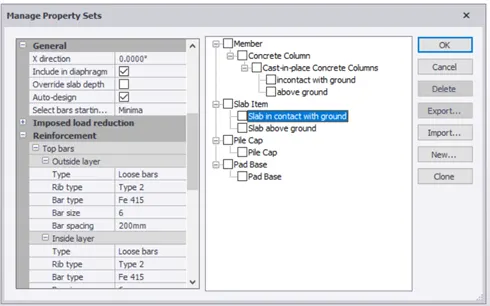
Result: By following this procedure we can create materials of desired properties.
3. Answer:
Aim: With reference to the input drawing as per Attachment 1, 1.1, and 2.1, study the steel building plan and summary of the plan. Based on the study assume the location of columns and beam and develop a hand sketch for each plan.
Procedure:
After opening the plan then first we must go through with the plan next, we have to see the arrangement of the grid and check the distances between them. Later we have to mark the column placement and beam placements.
Sketch 1:
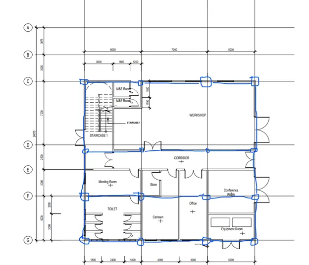
In this sketch F-4 column is at door then just go connect with the architect and if that column is necessary to place their then they will make changes accordingly.
Sketch 1.1:
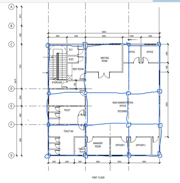
In this sketch column D-2 there is a coincidence with a door if there is any chance of changing the door then there is no issue. For this, we have to contact with an architect.
Sketch 2.1:
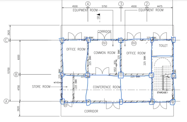
In this sketch there are no issues so then we can proceed with these column arrangements of the column and beam. There is only one secondary beam in the staircase area.
Result: By resolving all the issues then we can proceed with the further modeling of the project.
4. Answer:
Aim: Modeling the grid lines and construction levels as per Attachment 1, 1.1, and 1.2.
Procedure:
Step1: First click on the model tab in Ribbon Bar then go to construction levels in the levels panel.
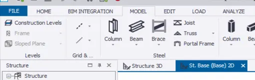
Step2: Then a window will appear like this. Next click on insert options to create new levels.
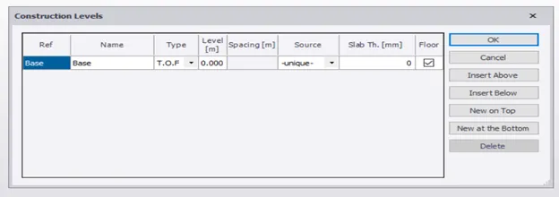
Step3: After creating the levels like this will appear. Finally, click on ok.
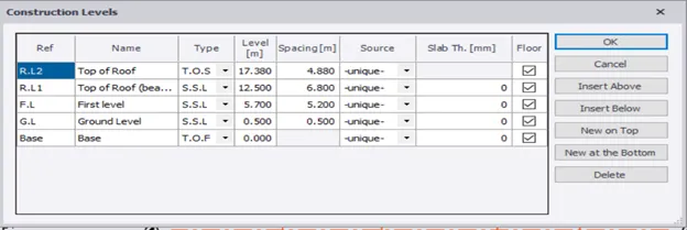
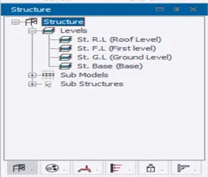
Step4: In the project workspace created levels will appear like this.
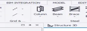
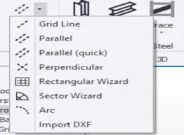
Step5: Then go to grids in the model tab various options will be there by using them we can create grids with specified distances.
Step6: Then created grids will appear like this.
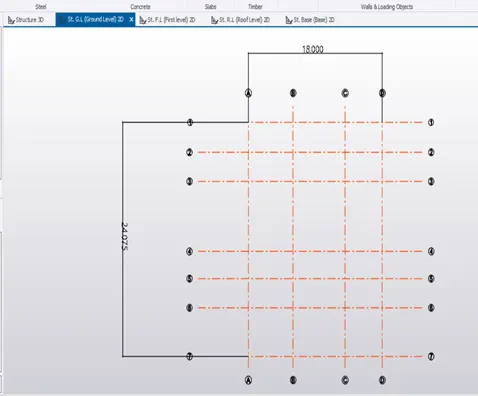
Result: By following this procedure we can create the grid lines with the required dimensions.