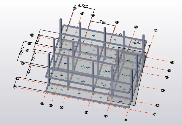
Week 7 Challenge
1. Setup model for RC building design and based on following parameters for cover
|
MEMBERS |
IN CONTACT WITH GROUND |
ABOVE GROUND |
|
Column |
50mm |
40mm |
|
Beam |
30mm |
25mm |
|
Slab |
30mm |
25mm |
|
Pilecap |
75mm |
|
|
Foundation |
50mm |
AIM: To set up model for RC building design based on the parameters for cover
|
MEMBERS |
IN CONTACT WITH GROUND |
ABOVE GROUND |
|
Column |
50mm |
40mm |
|
Beam |
30mm |
25mm |
|
Slab |
30mm |
25mm |
|
Pile cap |
75mm |
|
|
Foundation |
50mm |
TOOLS REQUIRED:
FILE
NEW
SETTINGS
HOME
SAVE AS
PROCEDURE:
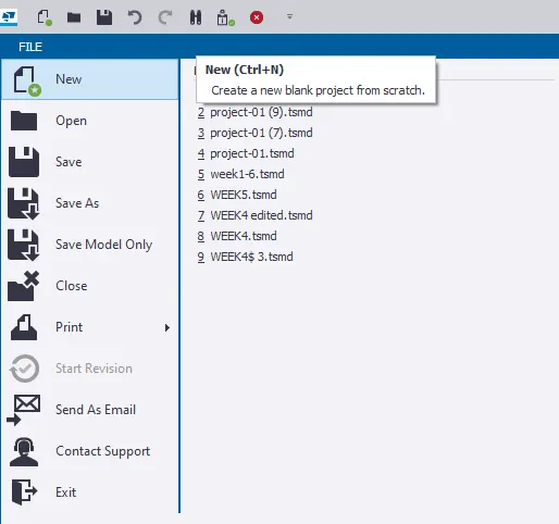
1. Firstly let us open a new file in Tekla software using new icon present in file tab.
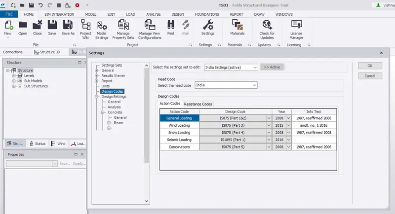
2. now let us select the settings icon from the home tab.
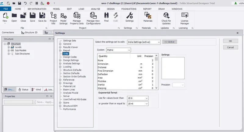
3. After selecting the settings icon a dialog box appears then let us modify settings according to our model that includes design codes, units.
units
4. now we will set up the model for the given parameters by using structure defaults.
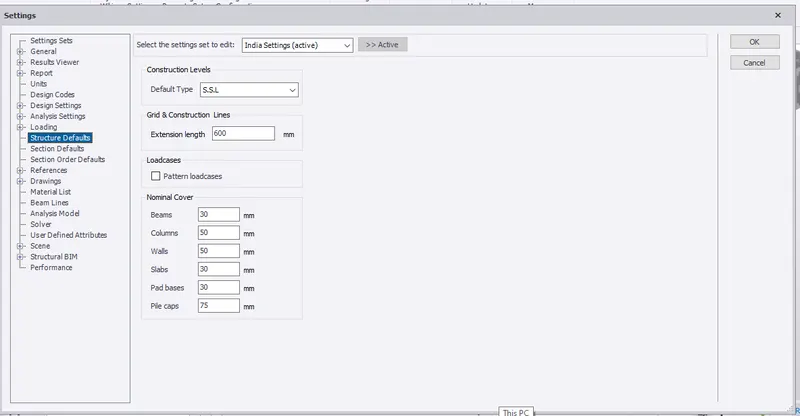
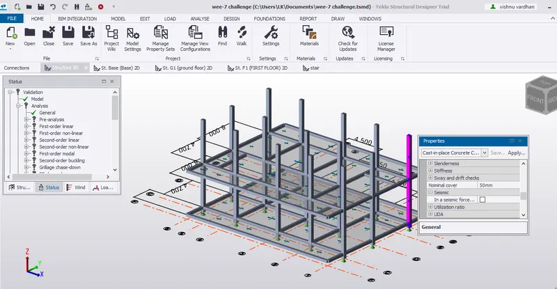
we can also change the cover after modeling the element in property window
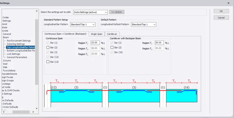
similarly we can change design settings of beams, columns, foundation, slabs, walls
5. SAVE THE FILE BY USING SAVE AS ICON.
RESULT:
WE HAVE SUCCESSFULLY CREATED A NEW FILE IN TEKLA AND SET UP MODEL FOR RC BUILDING DESIGN BASED ON THE GIVEN PARAMETERS.
2. Model grids as per the attachment 2,2.1 and 2.2
AIM: To model grids as per the attachment
TOOLS REQUIRED:
FILE
OPEN
CONSTRUCTION LEVEL
GRIDS
PROJECT BROWSER
PROPERTY WINDOW
PROCEDURE:
1. Open the saved file in Tekla software using the open icon present in file toolbar.
2. primarily let us model the construction level and name the level accordingly.
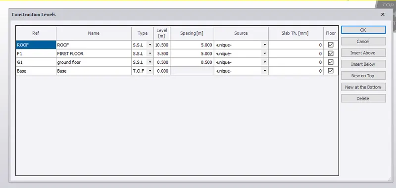
3. Now let us model grid for that, select grid icon present in the model toolbar.
4.now select any construction level which can be accessed through project browser
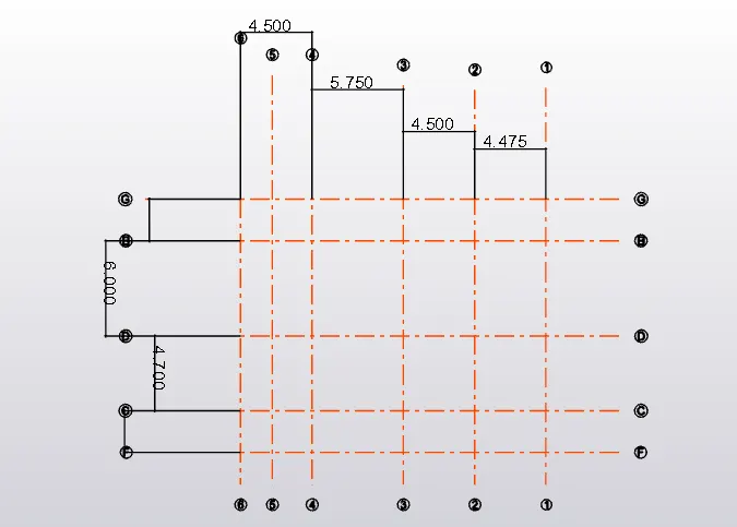
5.now according to the model provided in the attachment model the grid lines, we can make use of the parallel quick option to model grids.
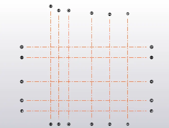
6 We can give dimensions of the grids by using dimension icon present.
RESULT:
WE HAVE MODELED GRIDS TO THE MODEL( according to the attachment) AFTER MODELING CONSTRUCTION LEVELS.final
3. Study the layout and write a summary for general arrangement of the structure
AIM: To study the layout and write a summary for general arrangement of the structure
TOOLS REQUIRED:
PROCEDURE:
1. Firstly open the attachment plan which is provided
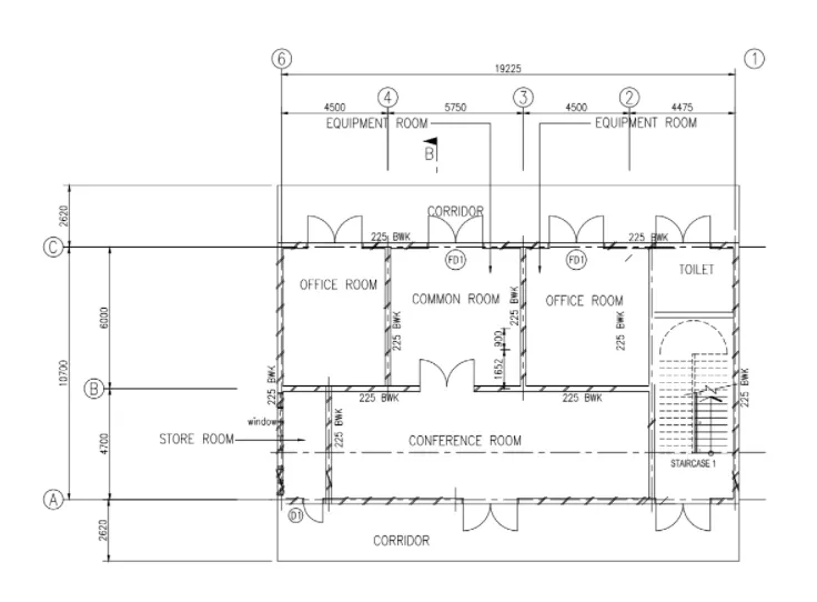
2. now let us model columns primarily
the longer part of the column should be aligned along the major dimension of the side
so open paint window and model column
for designing of column
should consider the position of pre-existing structures and disturbances present.
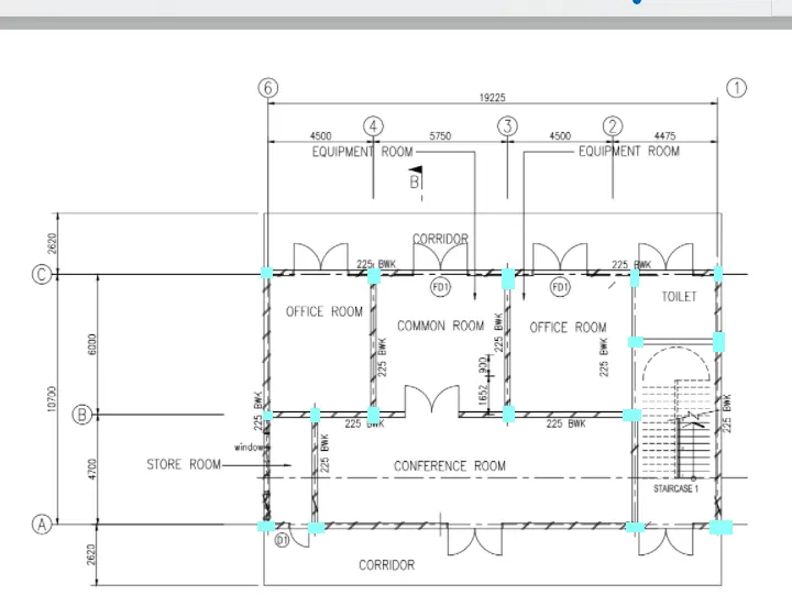
3. now let us model beams to the model by connecting with the columns
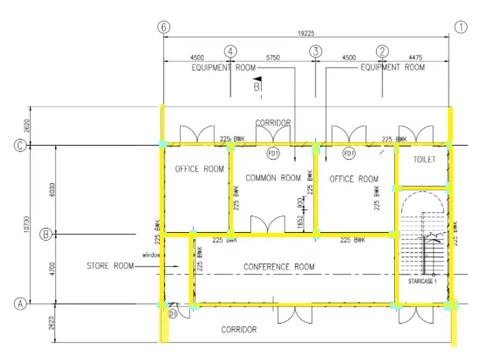
similarly, we can do it for the ground floor as well.
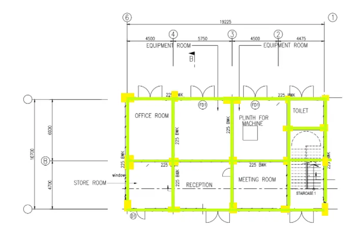
RESULTS:
WE HAVE Study the layout and write a summary for general arrangement of the structure
i.e we have located columns ( and shown how should be the position of column)
and have modeled columns using the paint window and the final output is
4. Model RC columns, beams and slabs as per your general arrangement
AIM: TO MODEL RC COLUMNS, BEAMS, AND SLABS FOR OUR MODEL.
TOOLS REQUIRED:
FILE
OPEN
MANAGE PROPERTY SET
GRID
BEAM
COLUMN
SLA
PROPERTY WINDOW
PROJECT BROWSER
VALIDATE
PROCEDURE:
1. Open the saved file in Tekla software using open icon present in the file tab.
2.Now let us model column for the model for that Now select the manage property set icon present in the home tab
3. After selecting the manage property set icon a dialog box appears, let us select concrete column and select the required parameters( grade, crossectional area)
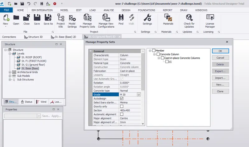
4. now select column icon present in the model toolbar and according to the plan, model the columns
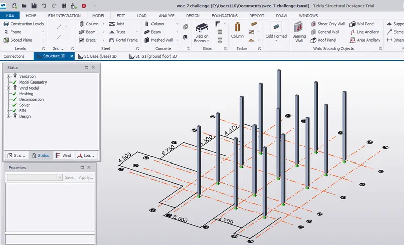
detailed view of columns with the help of seen content
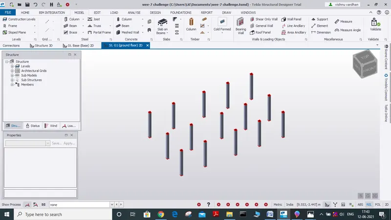
5. using the properties window we can alter the properties of the column
6. now let us model beams for that similar to columns let us create new property beam with the help of manage property set icon.
7. Using project window let us select a construction level say ground floor
8. now let us model beam with the help of grid lines
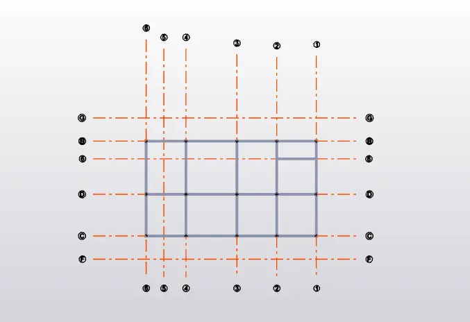
9. similarly let us model beams in first floor as well
10. for modeling of beams for varanda there will be a vaildation problem for that we have to right click on the member and change the beam support as cantiliver end
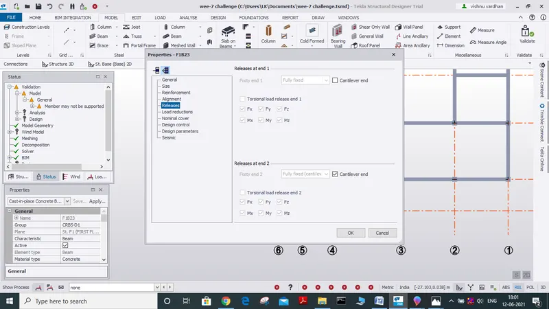
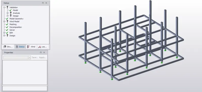
final position of beams for ground floor
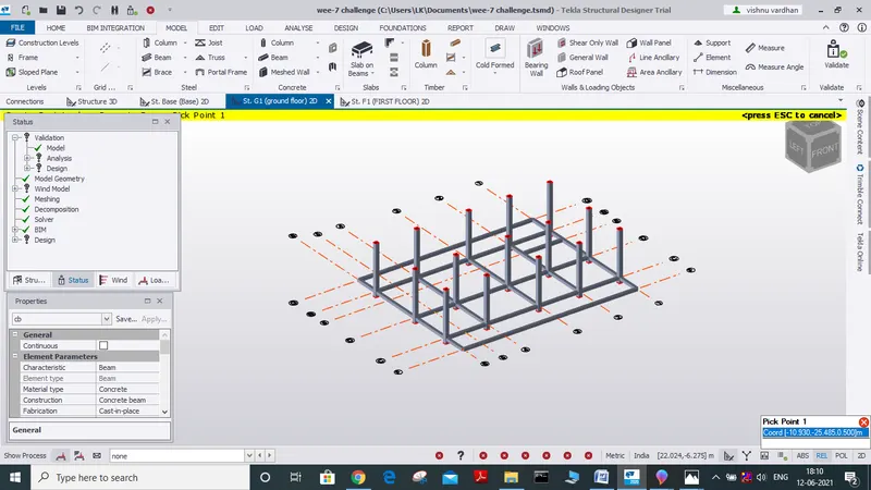
11. view of model with beams and columns modeled in 3D
12. now let us model slab for our model
for that select slab icon present in the model toolbar
13.providing slab to model for ground floor
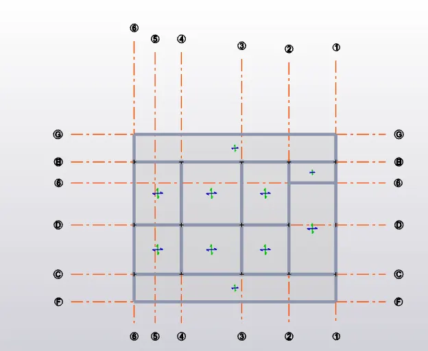
in the same way model slab for first floor
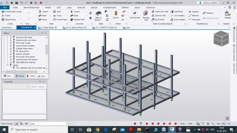
14 view of model after modeling slab (in 3d )
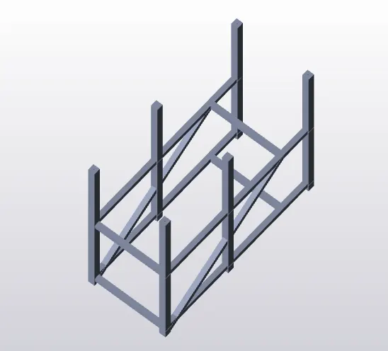
15) Now let us model staircase for that
select the corners where we are designing staircase and right-click on them
lots of options that appear select add to substructure option and name it
now access it through project browser and select slop sloped frames option and select the corners
15) VALIDATE THE MODEL AFTER EVERY STEP TO AVOID ERRORS.
RESULT:
WEe have successfully Modeled RC columns, beams and slabs as per the given plan with help of grids, construction level
final model after modeling columns, beams,slab is
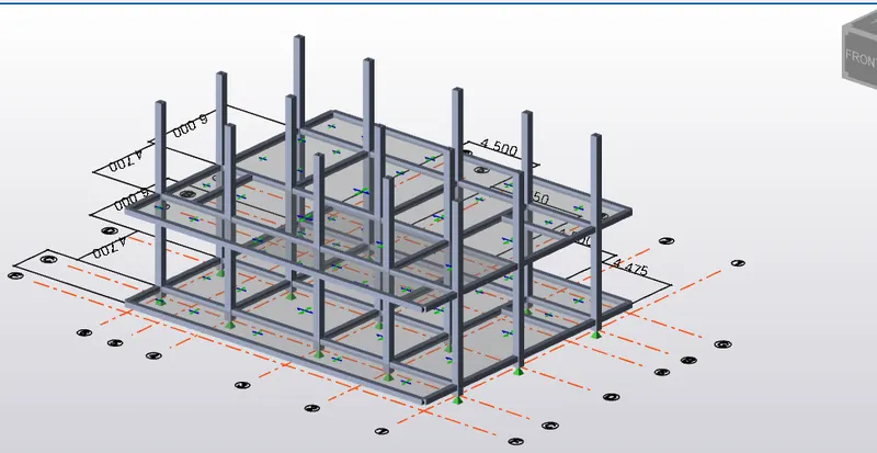
after modeling stairs