REVIT_3D Rendering of a House plan_Project 1
1A) AIM: to design the ceiling to the model created preceding a floor design.
TOOLS/COMMANDS REQUIRED :
FILE
OPEN
CLIPBOARD
PASTE
CEILING
ROOF
OFFSET
3D VIEW
VIEW
PROCEDURE:
1. Open the saved project, using the file icon.
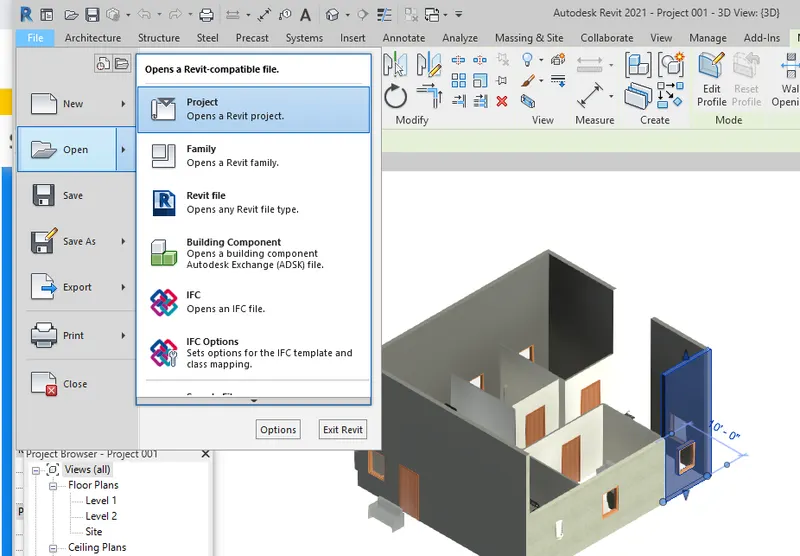
2. Then select the model in level 1 to the clipboard icon which is present in the manage toolbar.
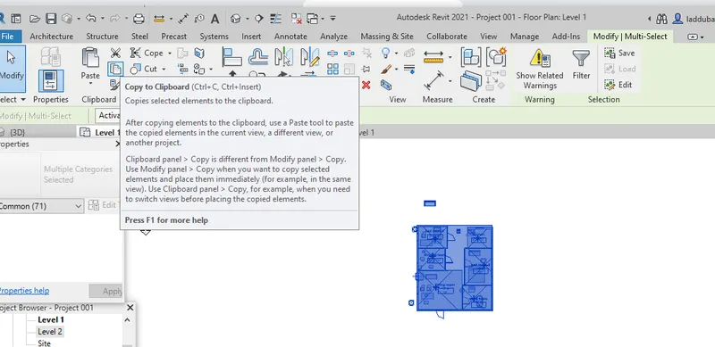
3. then using the paste icon we can select the option place in the selected level.
4. then choose the ceiling icon where we can align the ceiling for the model.
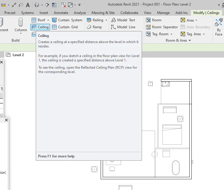
5. then align the CEILING to level and use the 3D icon to view the model's ceiling.
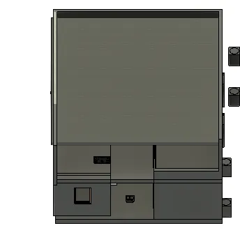
6. modify the roof, ceiling by using the properties icon.
RESULT:
HERE WE HAVE ADDED CEILING TO THE MODEL AND FLOOR, PROCEEDING OUR PREVIOUS MODEL.
2A) AIM: modeling a roof to the model and adjusting the roof slope to 10 degrees.
TOOLS REQUIRED:
FILE
OPEN
ROOF( BY FOOTPRINT)
PROPERTIES
PROJECT BROWSER
MODIFY
ARCHITECTURAL TAB
ATTACH TO TOP
PROCEDURE:
1. open the saved project created using the file icon.
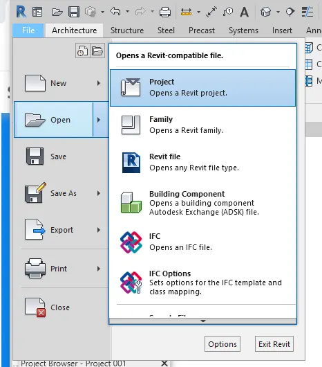
2. then select the roof icon which is present in ARCHITECTURAL TOOLBAR.
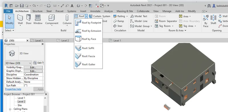
3. there are several ways in which we can arrange which will be appeared, based our convenience we can select any of that,
here we will select the roof by footprint option.
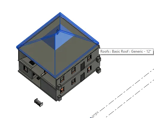
4. then set the roof on the ceiling of the first floor and using the properties icon we could set the properties like material, slope, thickness.
5. here we are selecting the slope as 10 degrees.
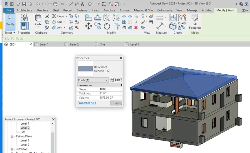
RESULT:
The ROOF FOR THE MODEL is laid and the slope is adjusted to 10 degrees.
3A) AIM: Viewing the architectural and structural view of the model.
TOOLS/COMMAND REQUIRED:
file
architectural tab
open
plan view
property browser
floor plan
first floor
PROCEDURE:
1. open the created project file using the file icon and then click on the open tab.
a. for the architectural plan.
# click on the view icon then select the plan view icon.
# there are several options available in it where for the architectural plan we should select the floor plan icon.
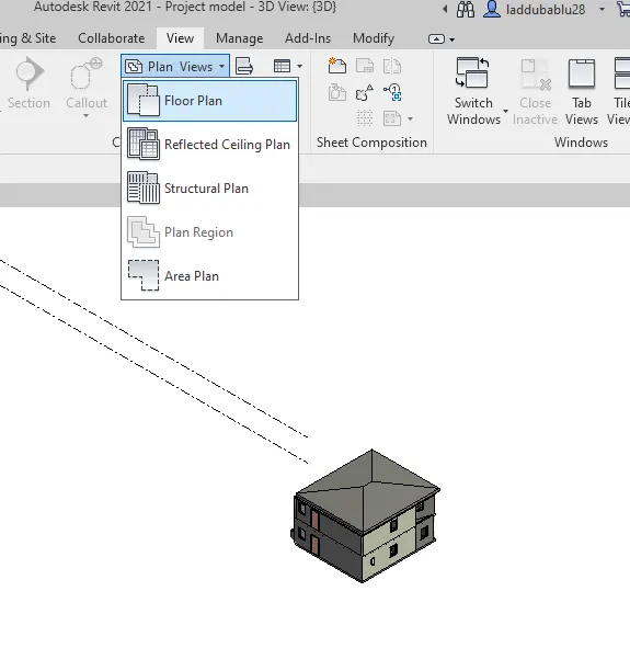
# Then select the FLOOR for which we have to view the architecture plan
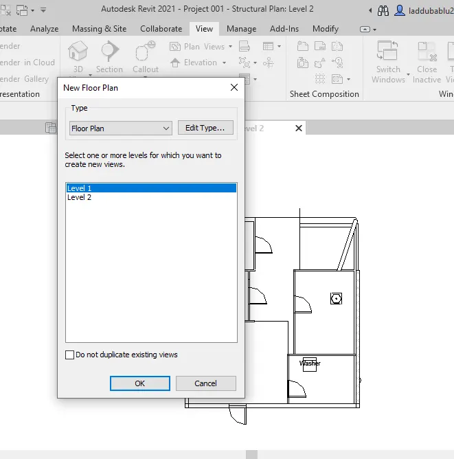
b. for structural view
# after clicking the plan view icon select the icon structural view.
# where we can view the structural plan of the model.
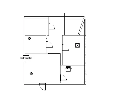
RESULT:
view the structural and architectural plan of the model.
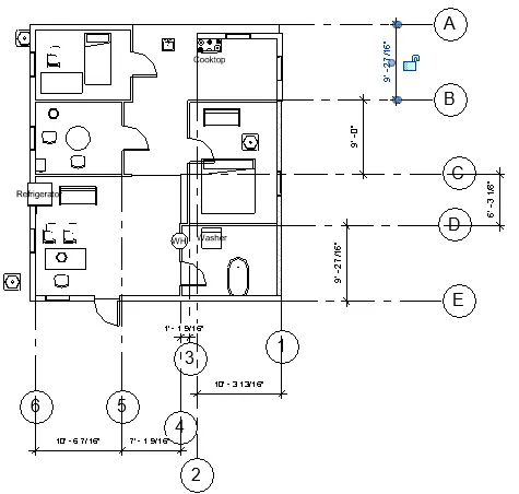
4A) AIM: To ADD DIMENSIONS FOR THE COMPONENTS OF BOTH STRUCTURAL AND ARCHITECTURAL PLAN AND MAKE USE OF GRID LINES FOR ALIGNING COMPONENTS OF THE MODEL.
TOOLS REQUIRED:
annotate
file
open
grid
align
structural plan
properties
architectural tab.
PROCEDURE:
1.OPEN THE PROJECT FILE FROM FILE MENU.
2.Then open the floor(ground/first-floor) plan from the property browser.
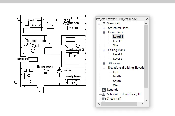
3.then select the grid icon available in the architectural tab.
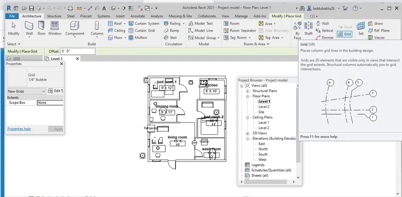
4. then place the grid lines and make necessary changes in the model like the position of components, can measure the dimensions using
align icon in the annotate toolbar
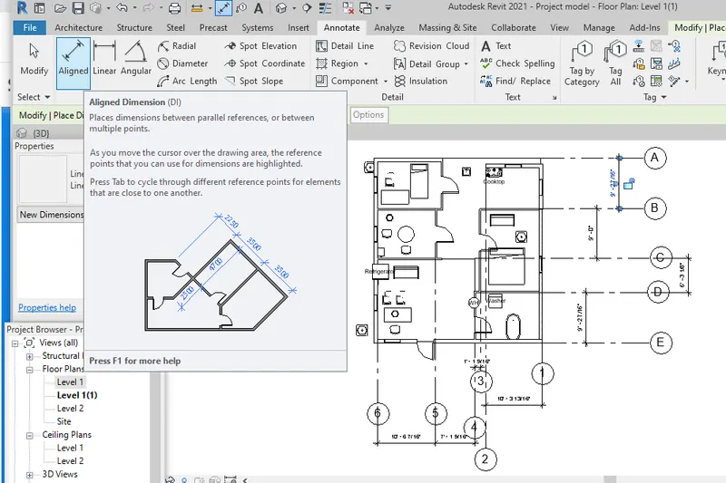
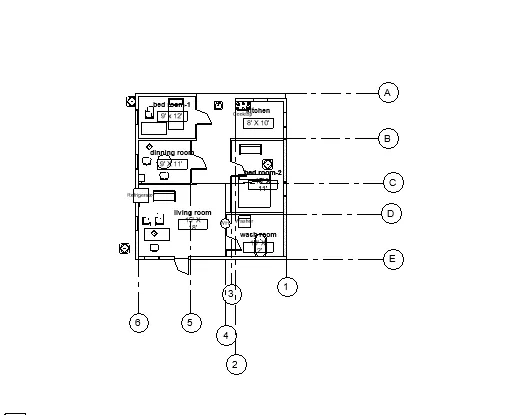
A. after arranging the grid lines open the floor plan to view the architectural plan of the model which can be given dimensions as well by using an annotate toolbar.
AND MARK DIMENSIONS OF THE COMPONENTS WITH THE HELP OF GRID LINES.
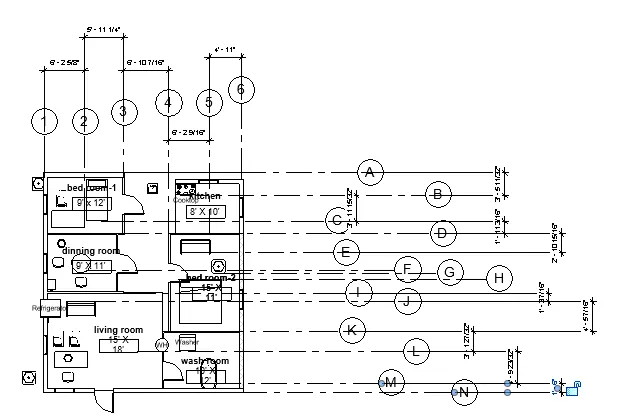
B.use the structural plan icon which is present in the view icon to view the structural plan of the model and arrange the structural components of the model and can use grid lines for detailed plan and components
RESULT:
WE HAVE ADDED DIMENSIONS TO THE ARCHITECTURAL AND STRUCTURAL PLAN OF THE MODEL, WITH RESPECT TO GRIDLINES.
5A) AIM: to create the sheet template and adjust its parameters.
TOOLS/COMMANDS REQUIRED:
view
sheet
properties
file
open
load family
PROCEDURE:
1. Open the project file using the file icon.
2. then in the view icon we could see the sheet icon choose it to, create a new sheet.
3. there is the default size of the sheet is present we can choose it or if we want a different size we can load and select the appropriate size.
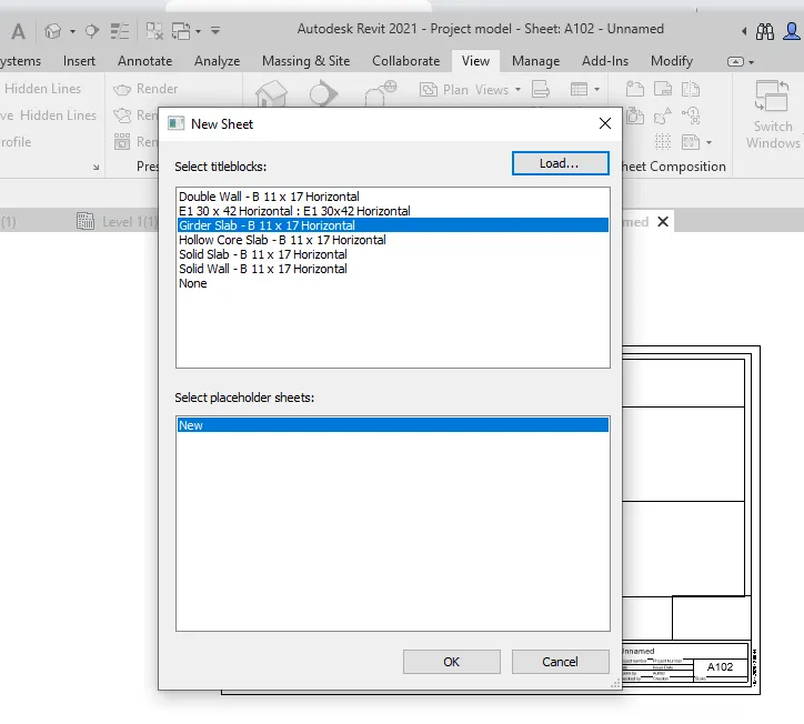
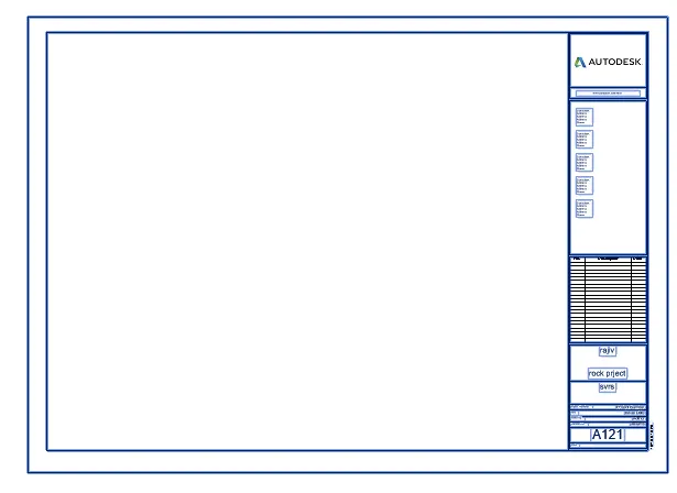
4. here we can change the parameters like an owner, project name, designed by, date, etc in the sheet by using the
properties menu.
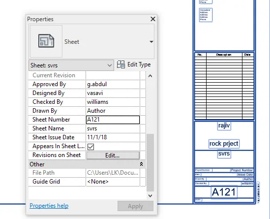
5. then make use of the title blocks icon to keep certain views in the sheet.
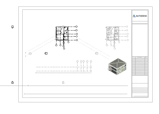
RESULT:
Here we have created a sheet for the model and adjusted the parameters of the model using the properties tab.
6A) AIM: using the elevation and create different elevation views i.e, north, south, east, west.
TOOLS/COMMANDS REQUIRED:
elevation
open
file
view
property browser
architectural tab.
PROCEDURE:
1. OPEN THE PROJECT FILE USING FILE ICON.
2. Then from the access toolbar select the view icon where we can select the elevation icon.
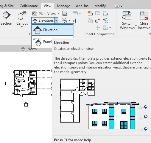
3. we can place these elevations in different directions and positions for various views of the model.
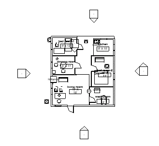
4. we can view the views in the project browser.
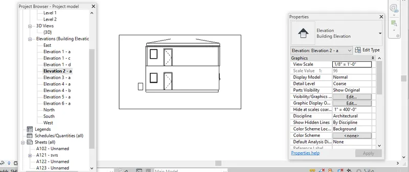
RESULT: We have created various elevation views for the model.
7A) AIM: PRODUCING SECTION VIEW OF THE MODEL.
TOOLS/COMMANDS REQUIRED:
open
file
section
view
property browser
architectural tab.
PROCEDURE:
1. OPEN the saved project using the file icon.
2. then click the section menu which is present in the view toolbar.
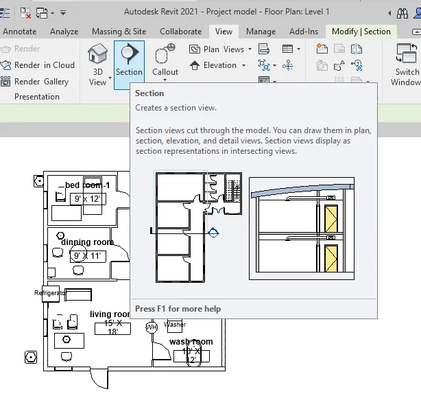
3. then place the section line which can be aligned in the desired location.

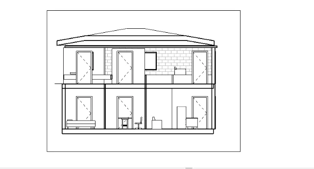
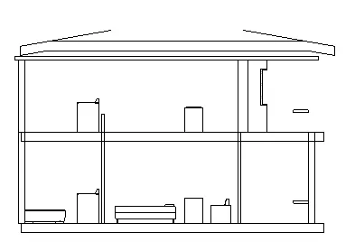
4. once you placed the section line we can see the section view in the property browser and we can name the view as well and view it.
RESULT:
Here we have produced the sectional views for the model.
8A) AIM: To classify the views into the design and documentation category using the property browser.
TOOLS/COMMANDS REQUIRED:
open
file
project browser.
browser organizations
new
architectural tab
property tab.
PROCEDURE:
1. Open the project file using the file icon.
2. from the project browser click the view icon (right-click).
3. then select browser organizations available after selecting the view tab.
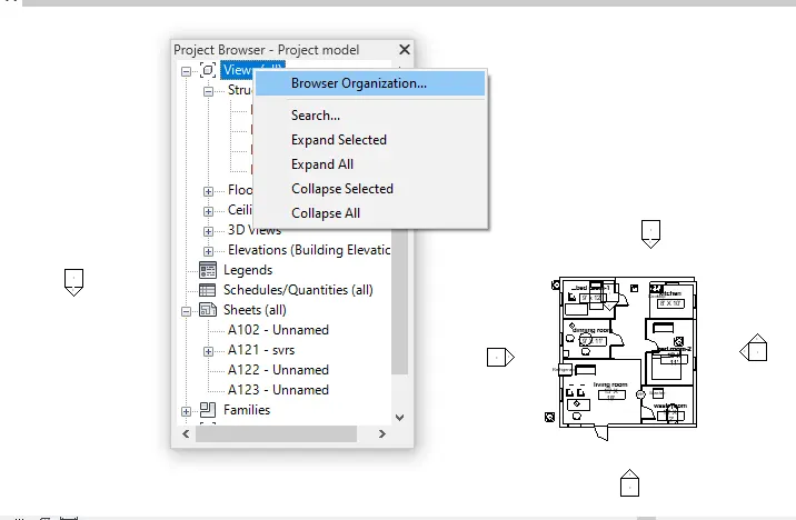
4. then click the new tab, and after clicking, it asks us for a new name.
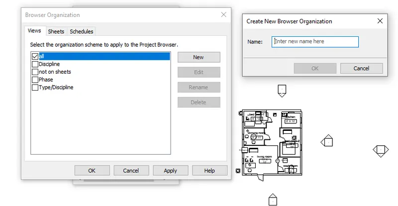
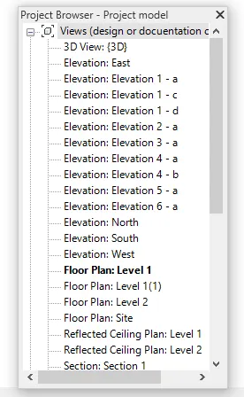
5. we can save the name as design and documentation and the views are now saved in the design and documentation category.
RESULT:
WE HAVE CLASSIFIED THE VIEWS OF OUR MODEL TO DESIGN AND DOCUMENTATION CATEGORY.
9A) AIM: TO CREATE SHEETS FOR VARIOUS PLANS AND ELEVATIONS FOR THE MODEL.
TOOLS/COMMANDS REQUIRED:
file
open
architectural tube
sheet
view
elevation
property.
project browser.
PROCEDURE:
1.Open the project file using the file icon
2. Click the view menu and select the sheet icon, then we can select the dimensions of the sheet for more dimensions
we can use the load family option and select the necessary dimension of the sheet in the title blocks.
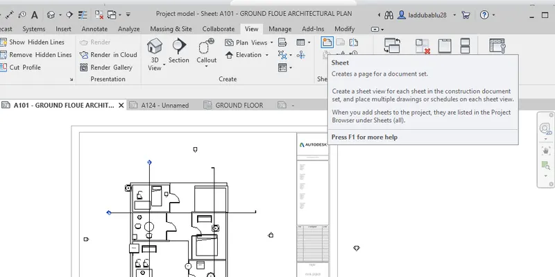
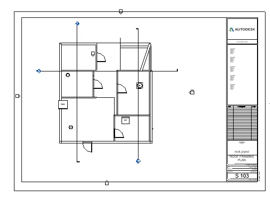
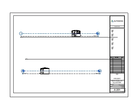
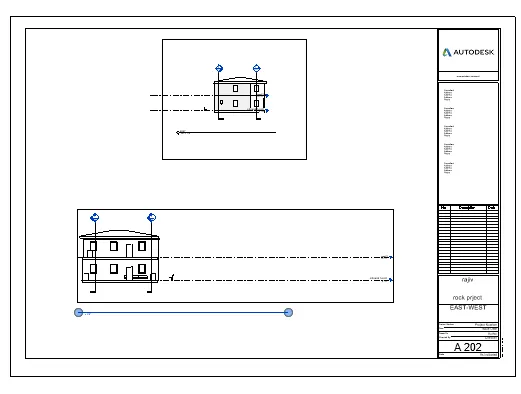
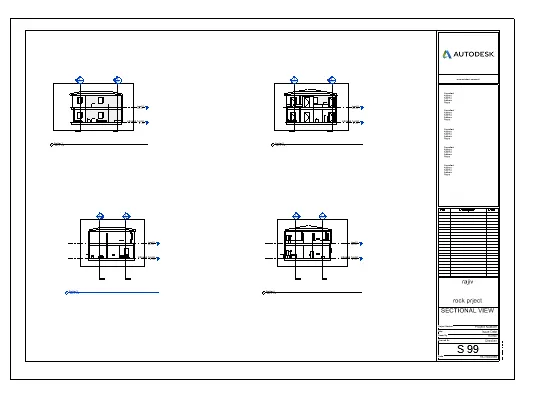
THEN CREATE THE FOLLOWING SHEETS
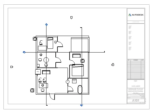
A101-GROUND FLOOR ARCHITECTURE PLAN
LOCATE THE GROUND FLOOR ARCHITECTURAL PLAN UN THE SHEET AND USING
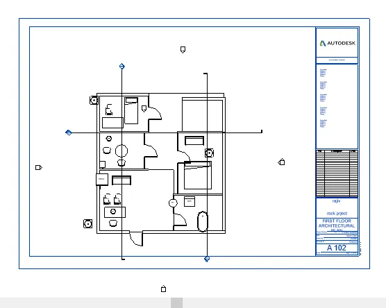
B. A 102 FIRST FLOOR ARCHITECTURAL PLAN
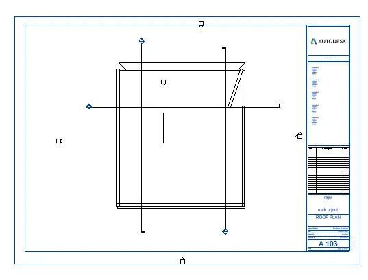
C) A103-ROOF PLAN
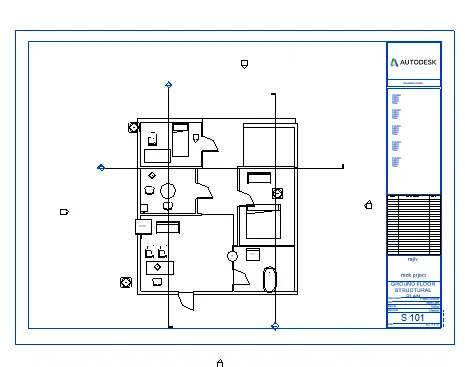
D. S101-GROUND FLOOR STRUCTURAL PLAN
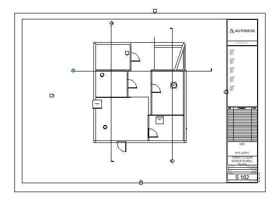
E. S102-FIRST FLOOR STRUCTURAL PLAN
F. S103- ROOF FRAMING PLAN
G. A-201 NORTH-SOUTH ELEVATION
H. A-202 EAST WEST ELEVATIONS
I S-99 SECTION VIEW
RESULT:
HERE WE HAVE CREATED VARIOUS SHEETS FOR VARIOUS VIEWS OF THE MODEL.
10A) AIM: TO CREATE 3 D VIEW USUNG CAMERA PROPERTY FOR ALL THE ROOMS OF THE MODEL AND CREATING SHEETS TO INCLUDE
THOSE VIEWS
TOOLS/COMMANDS REQUIRED:
open
file
property
project browser
camera view
3 D view
view
sheet
load family
PROCEDURE:
1. OPEN THE PROJECT FILE USING FILE ICON.
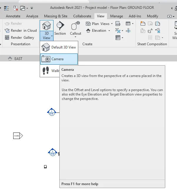
2. From the view icon click the camera option of 3d view.
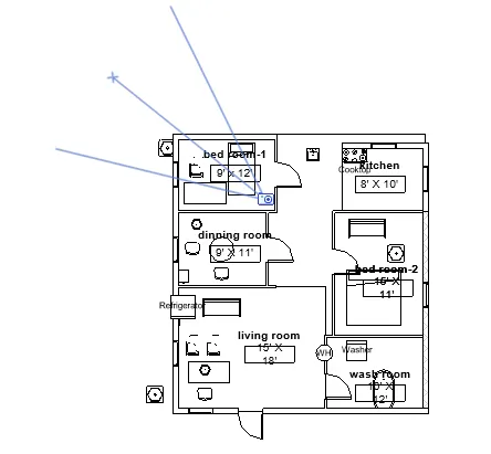
3. locate points for the position of the camera.
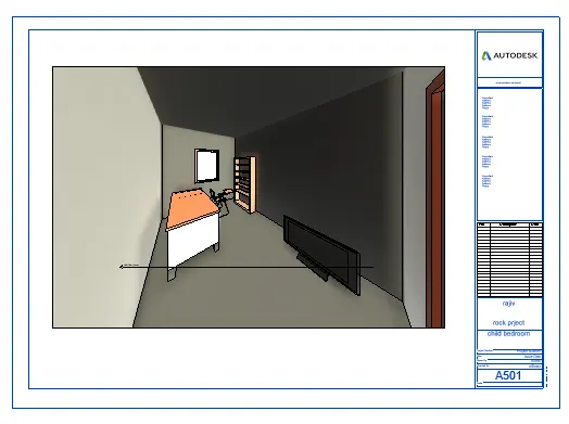
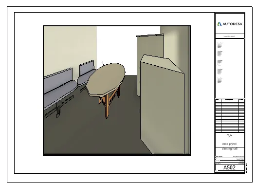
4. then create sheets from the view icon and create sheets for different rooms.
A-501 CHILD ROOM
A-502 DINING HALL
A-503 KITCHEN
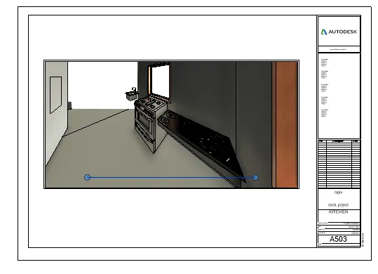
A-504 LIVING ROOM
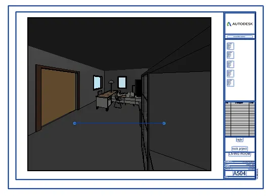
A-504 WASHROOM
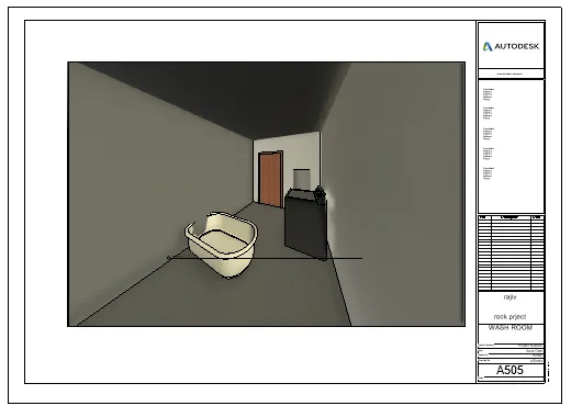
A-506 MASTER BEDROOM
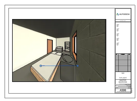
RESULT:
WE HAVE CREATED 3D CAMERA VIEWS FOR DIFFERENT ROOMS OF THE MODEL AND ALSO CREATED SHEETS TO SHOW THE
ROOM VIEWS AND DETAILED IT THROUGH SHEETS.