Week 2 Challenge
1A) BIM is a 3D software-based model in Revit which involves the gathering of information for the project and can be used to access Revit by different disciplines simultaneously and can help in designing an efficient plan and can help in computing.
BIM is divided into 2 categories
1. COORDINATION: this category enables the multi-disciplines of engineers to work together.
eg: a civil engineer and a mechanical engineer can work together for designing a project simultaneously which can save time and result in an efficient project.
2. computation: this category enables us to compute the project, which involves in scheduling material/quantity, analyzing energy and also loads, flow, etc
- features of BIM
- multi-discipline which can be accessed simultaneously by diff discipline users simultaneously.
- computing the materials, quantity schedule.
- computing loads etc
Benefits of using BIM over another 2D cad tools :
Because of real-time modeling feature i.e change in one view automatically results in effect in other views which can help us
in saving time and get an efficient design.
for example, if we make a change in the top view the side view and front view are automatically adjusted.
2A) AIM: to pick an element from the family which is present in the categories and insert it into the file.
TOOLS/commands REQUIRED: wall
insert
load family
PROCEDURE:
1. create a layout of any ( rectangular) crosssection.
2. Then click on the Insert tab, then we can find an icon by name load family.
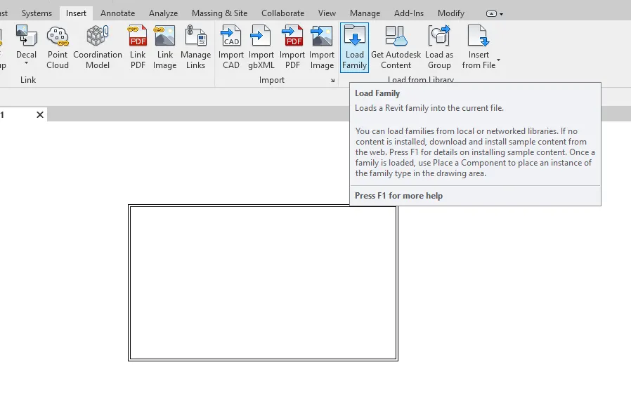
3. we can find different categories of elements. then we can select the element which is to be inserted in the model.
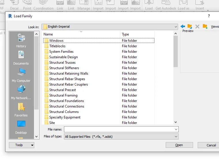
4. select the elements that are to be present in the model.
RESULT:
the elements are inserted and can be used in the model.
3A)Aim: Setting up a project and providing information to the project and setting back up to the project
TOOLS/commands REQUIRED: file
save as
manage
project information
backups.
PROCEDURE:
1. Create a project using a file icon followed by saving as an icon.
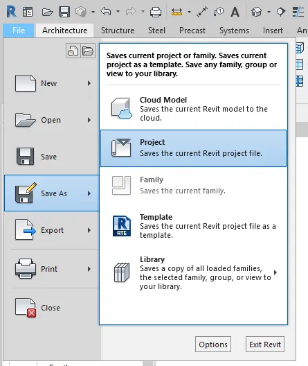
2. Then we can select a project from it.
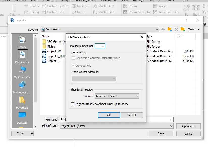
3. then file location access would appear then click options icon.
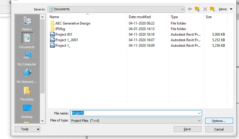
4. we could set options for max no of backup (3).
5. use the manage tab to save project information.
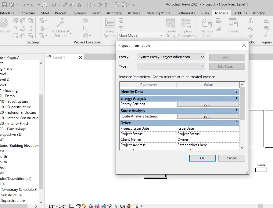
RESULTS:
we have saved the project, detailed the project information and set the maximum no of backups (3).
4) AIM: creating levels, grids with required dimensions.
TOOLS/COMMANDS REQUIRED:
- walls
- levels
- grids
- architectural template
PROCEDURE:
1. create a layout, select the 3D view icon.
2. then with the project browser open anyone of the east/west/north/south ways.
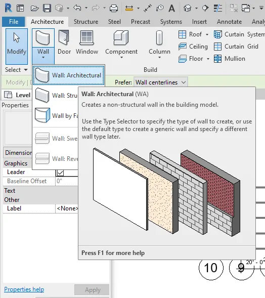
3. After selecting any of the elevations, then select the level tab after clicking the architectural tab.
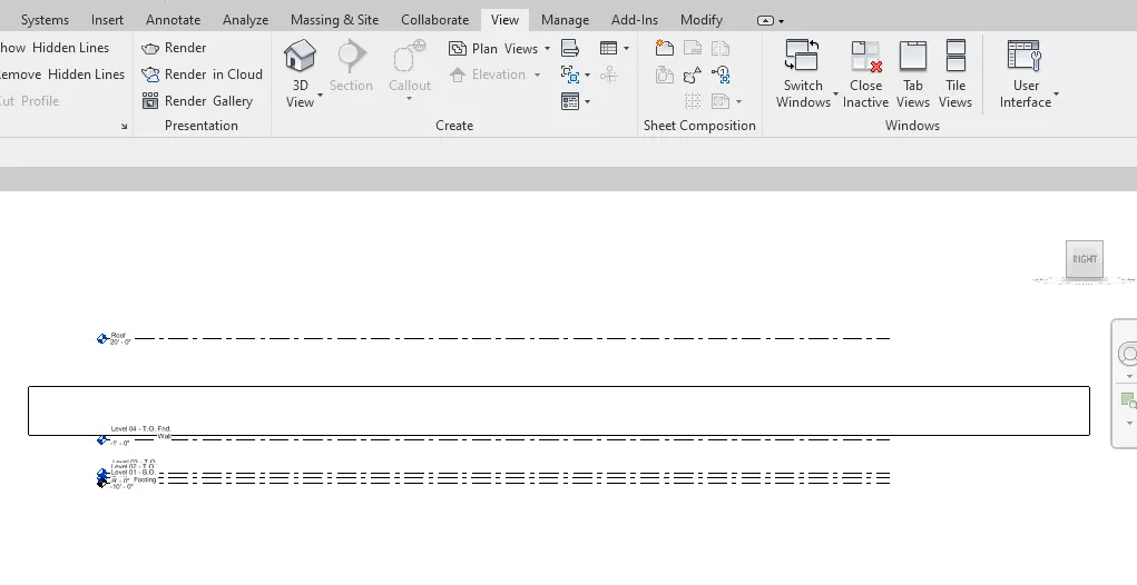
4. then adjust the dimensions of the level as required to be mentioned.
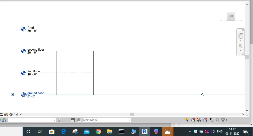
5. then after it goes back to level 1 and clicks the grid icon and locate longitudinal grids by no with a space of 20' and denote it by numbers.
6. and place transverse grid spacing 10' and name it by giving alphabets.
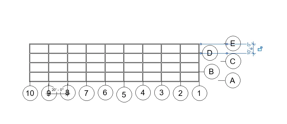
5A) AIM: To create a 3D modeling of a residential building.
TOOLS REQUIRED :
- walls & floors ( for layout)
- view
- 3D view
PROCEDURE:
1. Create a residential plan layout ( using wall icon after clicking the architectural template).
2.then we could use the floor option to embed the floor between walls.
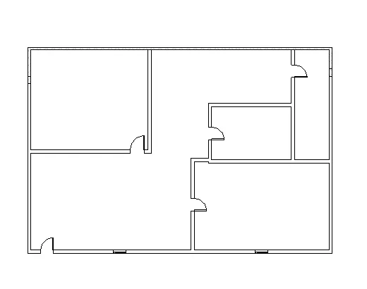
3. We could change the type of material used for walls, floor using properties.
3. click the view icon, then click on 3D view there we can view 3D view of the residential building layout.
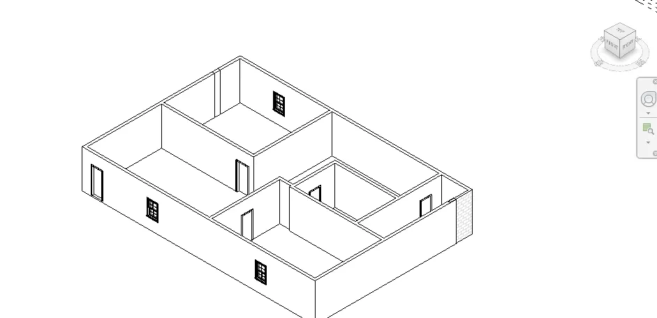
RESULT:
we have created a 3D view of the residential building.
6A) AIM: residential planning to include dimensions of the room and components required.
TOOLS REQUIRED:
- file
- open
- rooms
- doors
- windows( components)
- aligned
- annotate
PROCEDURE:
1. open the saved residential plan by using the file menu.
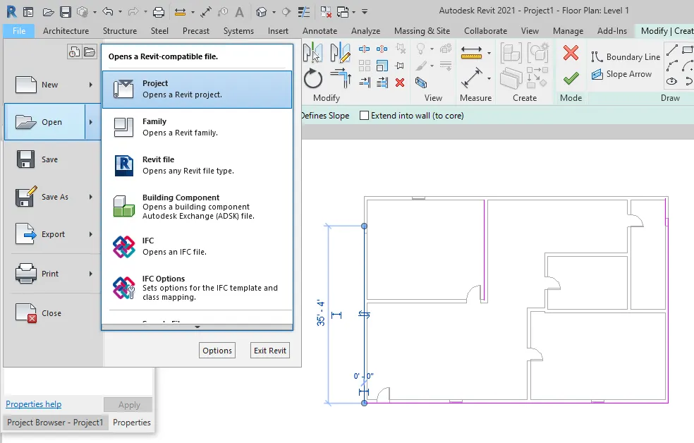
2. Then click on the room icon there we can use it to specify the rooms as living room, hall, etc and give dimensions to rooms by using the aligned toolbar.
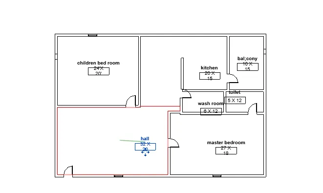
3. Then go to components and select whatever components we require.n here let us select doors, windows.
4. place them in the desired location.
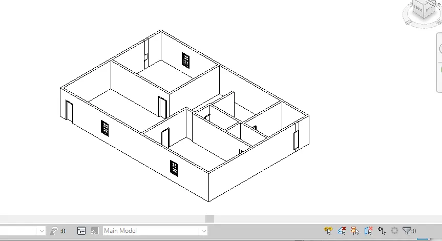
RESULT:
The residential building is now included with dimensions of room and dimensions of the room are mentioned.
7A) AIM: inserting model elements like a door, windows, tables, chair, couch, bed, etc into the model.
TOOLS REQUIRED:
- file
- open
- insert
- load family
PROCEDURE:
1. Open the saved project using the file icon.
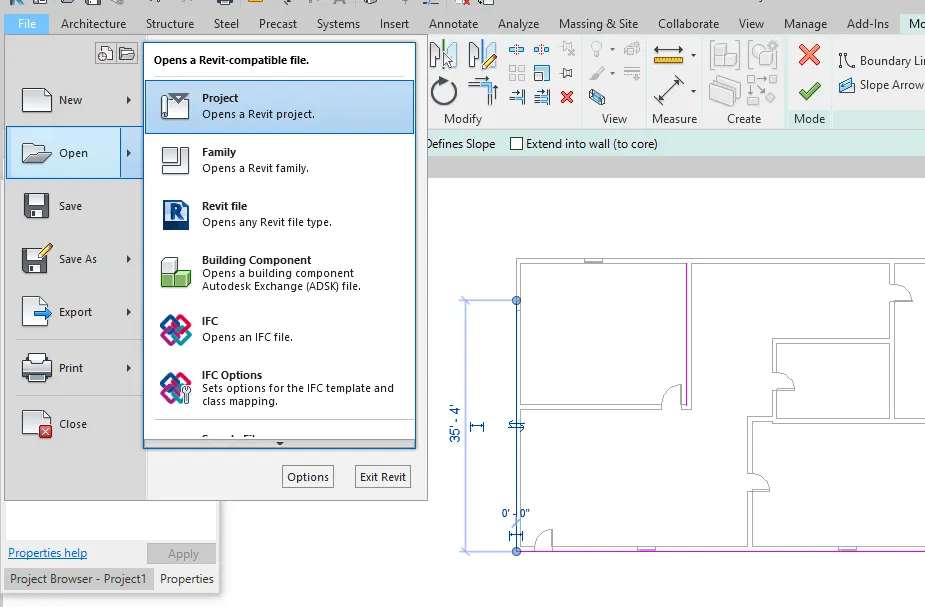
2. then click the insert menu there we will find the load family option where we can find various types of components in the saved location.
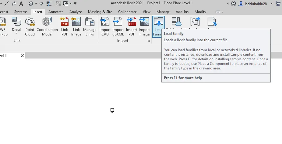
3. we can select desired components from the family and place them in the desired; location.
4. once selected we can click on components for different dimensions of the object.
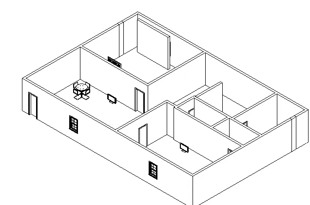
RESULT:
we can insert model elements like a door, window, etc in our model, I have added a bed, doors, tv, dining table to the model.