Week 7 Challenge
DESIGN AND ANALYSIS OF BRIDGE WITH WATER CURRENT LOADS
AIM
To Design and analyse a bridge with Water current loads using STAAD Pro. Software.
INTRODUCTION
As per the given data and standard formulas the water current load is being calculated manually.
Max. velocity = √2 x Vmean
= √2 x 3 = 4.24 m/s
Water current ,P = 52 KV^2
= 52 x 0.66 x 17
= 617.75 KN/m2
PROCEDURE
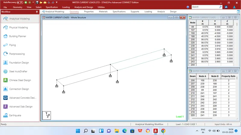
Step 1 - Create Nodes by entering the corresponding X/Y/Z values in the Node table for Creation of geometry for Truss bridge structure with elements such as Piers,Beams,Deck slab etc.,
Step 2 - After creating the nodes connect those nodes with add beam option.
Step 3 - Then Click specification tab and click fixed support tab
Step 4 - After that in create support dialog box add fixed support for all the piers in the geometry using assign for selected nodes option.
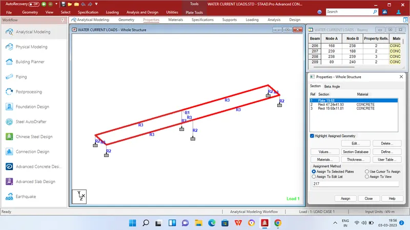
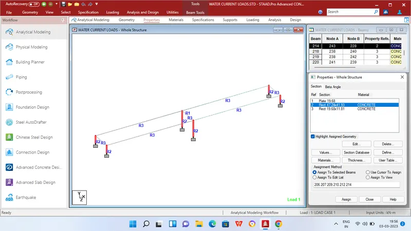
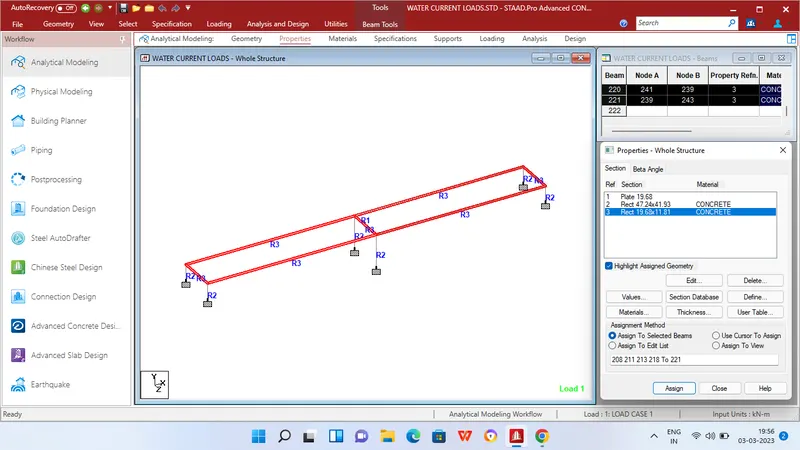
Step 5 - Then in Properties tab click Prismatic and add the Rectangle sections for beams and respective thickness for plates as given in the question data
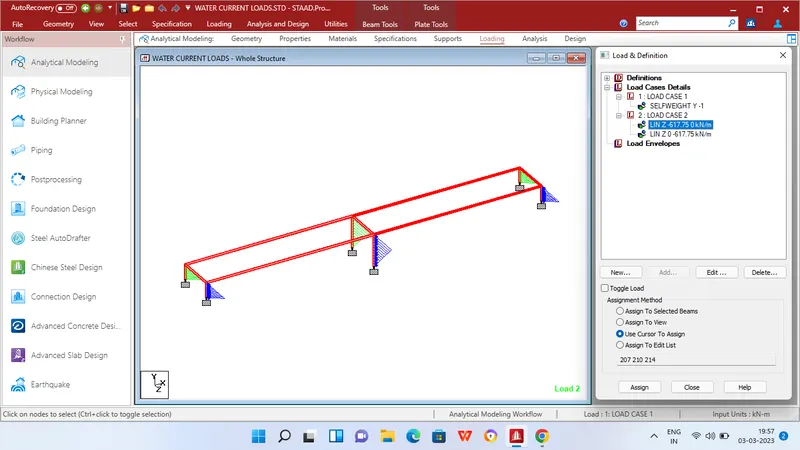
Step 6 - After adding the properties click Loading tab and add load cases for Self weight,water current load
Step 7 - Then apply self weight to the entire geometry.
Step 8 - After applying the self weight add Live member load - Linearly varying load of 617.75 as per manual calculation to the Piers of the bridge for full length of the pier
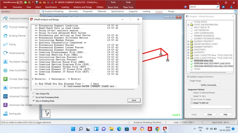
step 9 - Then in Analysis and design tab define commands for PERFORM ANALYSIS and click run analysis.
RESULTS
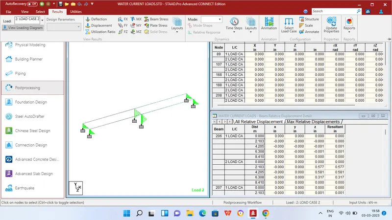
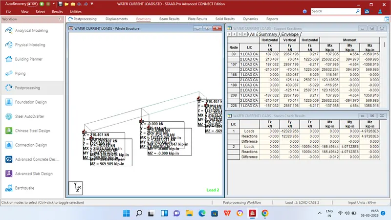
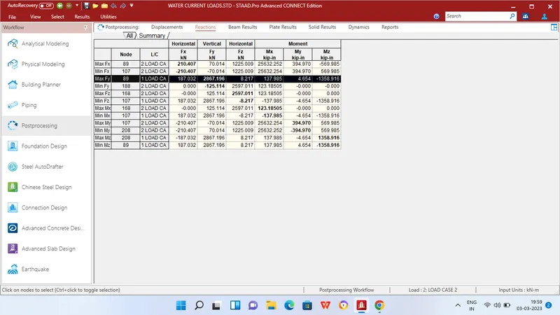
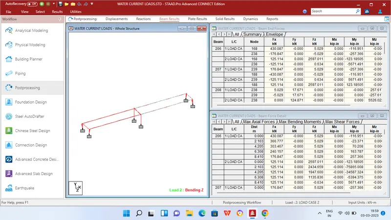
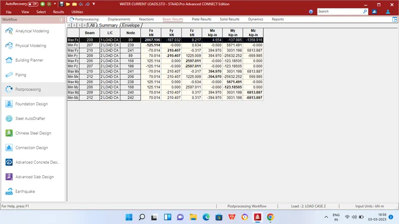
MAXIMUM BENDING MOMENT AT SUPPORT
Mx = 123.18 KN/m at Node 168
My = 394.97 KN/m at Node 107
Mz = 1358.91 KN/m at Node 208
MAXIMUM SHEAR FORCE AT SUPPORT
Fx = 210.4 KN/m at Node 89
Fy = 2867.19 KN/m at Node 89
Fz = 2597 KN/m at Node 168
MAXIMUM BENDING MOMENT AT BEAMS
Mx = 394.97 KN/m at Beam 210
My = 5671.29 KN/m at Beam 206
Mz = 6813.88 KN/m at Beam 209
MAXIMUM SHEAR FORCE AT BEAMS
Fx = 2867.19 KN/m at Beam 209
Fy = 210.4 KN/m at Beam 210
Fz = 2597 KN/m at Beam 206