Week 7- Base Unit Design Challenges 2
Aim
the main aim of this challenge is to design the base unit for the given car panel as per design constraints using CATIA V5 tool.
introduction
while coming to the introduction of the base unit in BIW fixture design we are mainly concern the following components to design first and then assemble with main body of the base ubit they are
Typical parts of the base unit are given as follows:
1 Base Plate: -
Th e base plate is a plate of 25 mm to 40 mm thickness.
The base plate has no of holes drilled on it which will act as mounting points for clamp unit, pin unit and so on.
2 Pedestal: -
It is used to connect the base plate with a floor plate.
The pedestal can be a standard part or a make part, depending on the size and height of the fixture.
Standard pedestals are available in different heights.
Pedestals are also available in different inclinations.
Depending on the size of the base plate, the number of a pedestal for a fixture can vary for load distribution.
3 Trucking channel: -
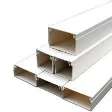
Trunking Channel is a duct that carries all the electrical and pneumatic connections(wires and pipes) for units of the tool.
It has a thickness of few millimetres.
4 Valve box: -
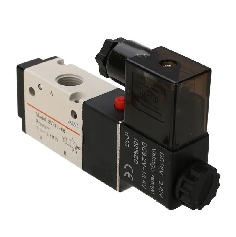
Valve Box is a standard part which contains all the valves for the pneumatic units. The valve box is the box which includes different solenoid valves. The pneumatic fixtures work on air pressure provided to it. So the arrangement of air pressure inlet & outlet is done within this valve box. The trunking channel includes all the pressure inlet cables going to the pneumatic parts of the fixture & protects them from damaging while operation is in process.
5 Eyebolt: -
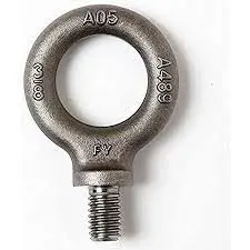
Eye Bolts are the bolts that are used to lift the fixture for transportation by inserting hooks into them.
For example, we usually use M20 bolts that are bolted on the base plate.
Used for transportation purpose, sometimes forklift holes will be provided.
6 Floor Plate:
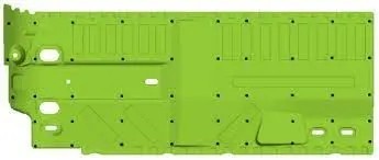
They are also known as foundation plate. They are grounded by using a fixed bolt.
10 mm clearance should be given between pedestal base plate and floor plate.
Weld bars need to use after the levelling is done by levelling screw.
Weldbars are steel plates along the sides of the base plate of a pedestal.
Weld bars are used to position the positions permanently.
POINTS NEED TO BE FOLLOW WHILE DESIGN THE BASE UNIT
1 Working Height:-
It depends on the nature of the manual or robotic welding fixture.
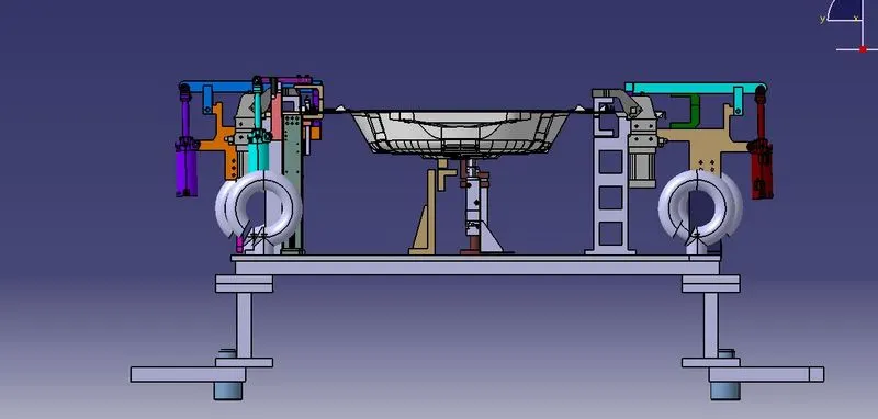
For manual fixture we need to consider the working height 850-1100 mm, depending upon the working height of the worker standard of a specific country will apply( In few countries human height is higher or lower e.g. US, Japan).If the base structure is made with a base plate having tubular structure welded below it we can reach to height 100 mm to ~250 mm.In this case to reach the working welding height we need to provide additional some leg structure which may have top and plate welded to the tube. the following images are shows the basic heights that are followed while designing the base units
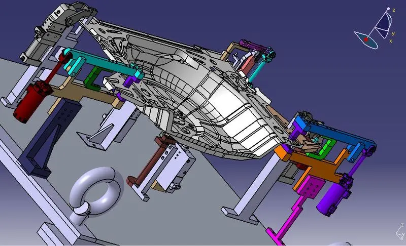
views of whole unit
iso metric view
front view
3-2-1 principle
3-2-1 principle is basis of any fixture design. Holding fixtures used in assembly operations often follow a 3-2-1 locating scheme to position parts. Under this scheme, three locators position a part in a primary plane or direction (e.g., high/low).
(3) minimum: Three locator blocks to establish part plane. Three locators or supports are placed under the work piece. Three locators are usually positioned at primary locating surfaces. This restrict two translation motion i.e. upward & downward & four rotational motion ( i.e. clockwise or anticlockwise). Together tree locators with clamp restrict six degrees of freedom.
(2) Round locating pin in a round hole that defines location in four directions (4 ways) perpendicular to the plane previously established. This restricts four axial movements.
(1) means restricting one degrees of freedom i.e. rotational motion about z axis clockwise or anticlockwise. Another diamond pin in hole is sufficient to prevent rotational motion around Z-axis.
Below figures shows how 3-2-1 principle is achieved. Three clamps restricts 6 degrees of freedom & two pin unit restrict 6 degrees of freedom.
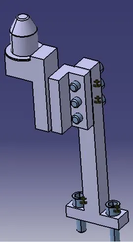
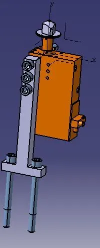
Different pin units that are designed they are
Round pin unit
retactable pin unit
simple clamp unit
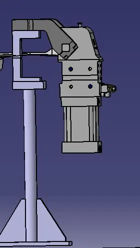
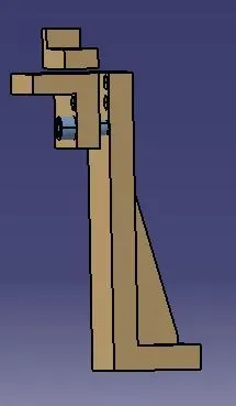
rest unit
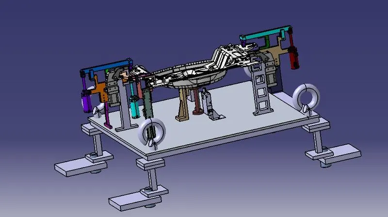
whole unit isometric view with base unit
conclusoin
hense the base unit and arrangement of the different units with car panel are designed as per instructions