Week 7- Base Unit Design Challenges 2
OBJECTIVE
To design the Base Units with all the weldments included. And add all the necessary Units for the fixture assembly for the given car panel.
Abstract
I have designed different types of pin units and clamp units and power clamp units and Rest Units for fixing the given fixture assembly. By using the 3-2-1 principle
Software
Catia V5
(3-2-1 principle) achieved by clamping & resting:
- The best & most cost-effective method of part location is referred to as the 3-2-1 method.
- . Fixtures work on of 3-2-1 principle.
- (3) Minimum: Three locator blocks to establish the part plane. Three locators or supports are placed under the workpiece. Three locators are usually positioned at the primary locating surface.
- . This restricts two axial movements downward & upward and four radial movements. Together, the three locators restrict six degrees of freedom.
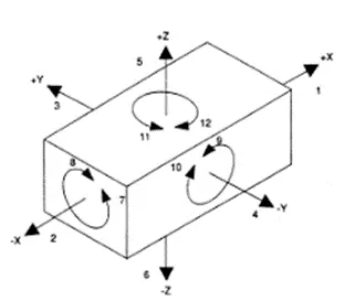
As by 3-2-1 method by introducing a minimum of 3 clamping & 3 resting blocks will restrict 6 degrees of freedom (DOF) and then 2axial movements and 4 radial movements
Important parts of the Base Unit
- Base unit
- PEDESTAL
- TRUNKING CHANNEL
- VALUE BOX
- MEASURING HOLE COVER
- EYEBOLTS
- FLOOR PLATE
- WELD BAR
Design Methodology of the Base unit
The main purpose of the base plate is to keep all the mounting attachments like pin unit, clamp_unit, rest_unit, etc. for base unit steel and aluminum can be used. and the thickness varies from 25mm to 40mm depending on the requirement but in my case, I used a 20mm thickness sheet as my base plate and in dimensions 1850mm X 1200mm X20mm
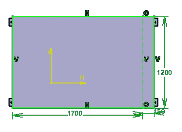
Fig Base unit
PEDESTAL
A pedestal is a part that connects the base plate to the floor plate. A pedestal is a standard part in general and in some cases, it can be welded frame integrated with the base plate standard pedestal can be of different heights and different sizes Depending on the size of the base plate, the number of pedestals varies for load distribution.
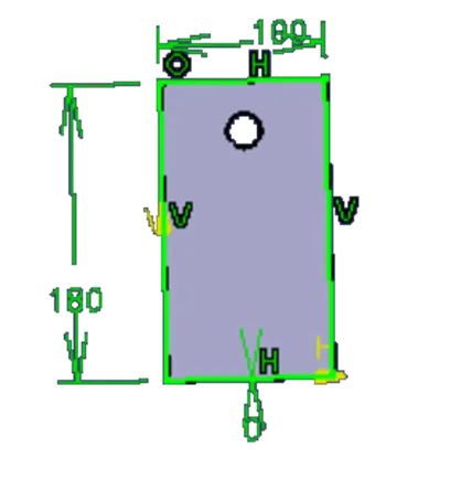
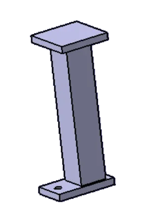
Fig Pedestal
TRUNKING CHANNEL
Trunking channels are nothing but the tube that can be carried all the electric and pneumatic cables for the base plate unit mounting parts
Value box
It is a junction box for the base unit the can connect all the electricity outputs
Eye bolts
To lift the base plate we need to add extra holding points for the base unit for that eye bolts are used
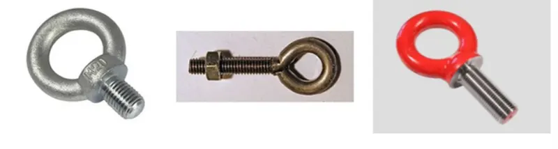
Fig Eyebolt
Design procedure for the base unit
Before designing the base unit we need to check all the 5 panels are obeying the 3-2-1 principal are not if any of the units is not there we need to fix the panel by adding an extra clamp unit or pin unit or a rest unit which is required at that position
Started with the NEW PRODUCT and name as P001_Z01_ST01_01_00_BASE_UNIT insert another project file for the base unit P001_Z01_ST01_01_01_WELD_PLATE and then insert the part file and name as P001_Z01_ST01_01_01.1_BASE_PLATE check all the attachments required for fixing the panel. Draw a sketch and pad it up to 20mm
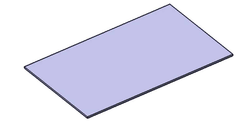
Fig BASE PLATE
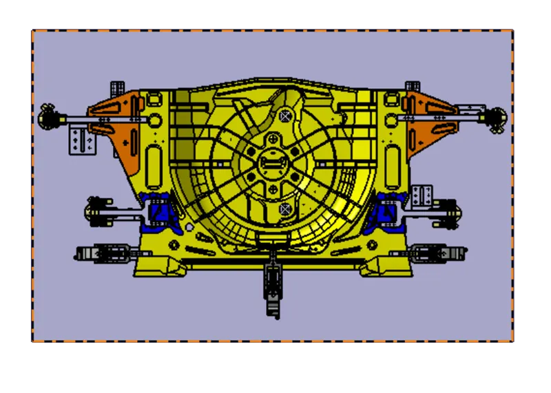
Fig BASE PLATE TOPVIEW CLERANCES
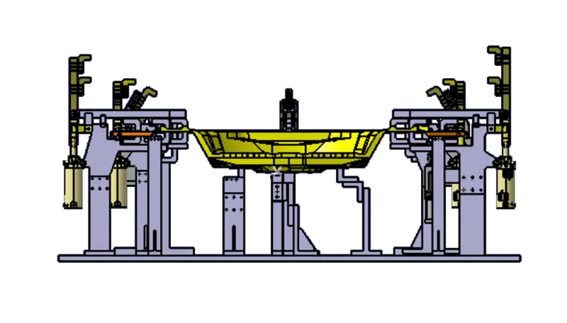
Fig BASE FRINT VIEW CLEARANCES
For the next step to give extra strength and support we need to add the supporting tubes for the base unit for the insert another part file and name as P001_Z01_ST01_01_01.2_SQ_TUBE_50X50X2X1160 and horizontal side P001_Z01_ST01_01_01.3_SQ_TUBE_50X50X2X1800.
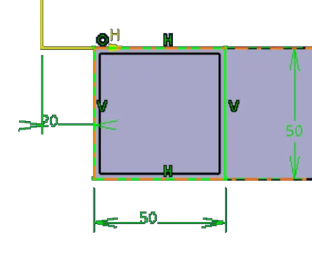
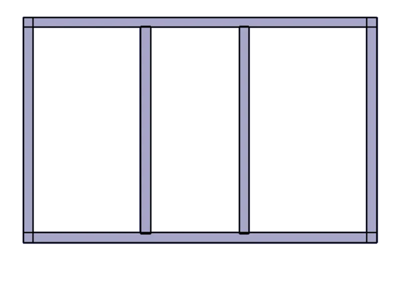
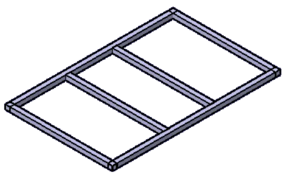
Fig BASE PLATE SUPPORTING FRAME
The next step is to add the extra plates for the mounting of base pillers for that I added a plate the similar plates are also present in the piller
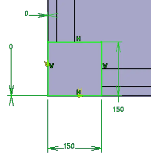
Fig BASE PLATE PEDESTEL ATTCHMENT
The next step is to add the working height of the base unit this can be given by the customer in my case I took the working height is1030mm for that I designed the piller of 400 mm and named the unit P001_Z01_ST01_01_01.2_SQ_TUBE_80X80X5X400.
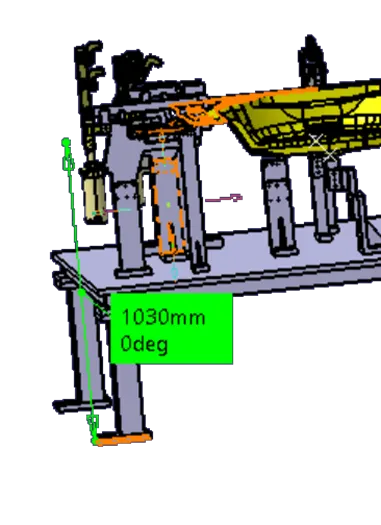

Fig PILLER
And the final step is to add the base mounting(pedestal) for the base unit
Fig BASE PLATE PEDESTAL
At the end copy for all the four sides of the base unit. This is all the views of the base unit
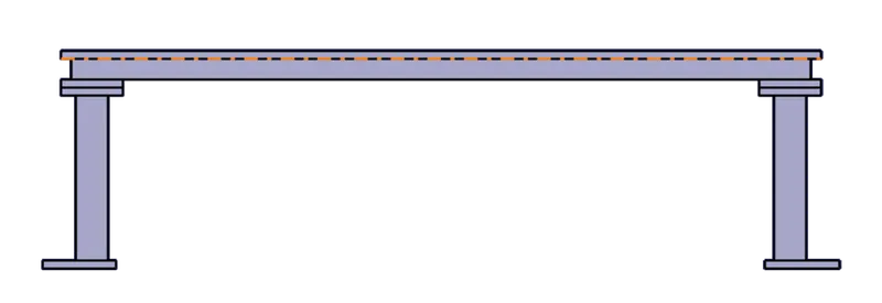
Fig BASE PLATE FINAL FRINT VIEW(WITHOUT PANNEL)
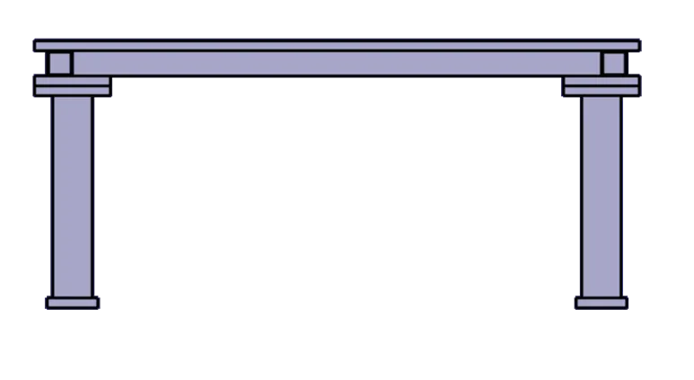
Fig BASE PLATE FINAL SIDE VIEW(WITH OUT PANNEL)
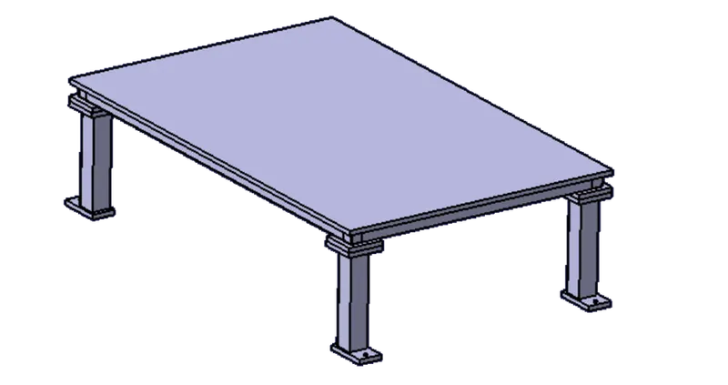
Fig BASE PLATE FINAL ISO VIEW(WITHOUT PANNEL)
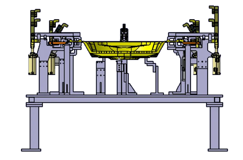
Fig BASE PLATE FINAL FRINT VIEW(WITH PANNEL)
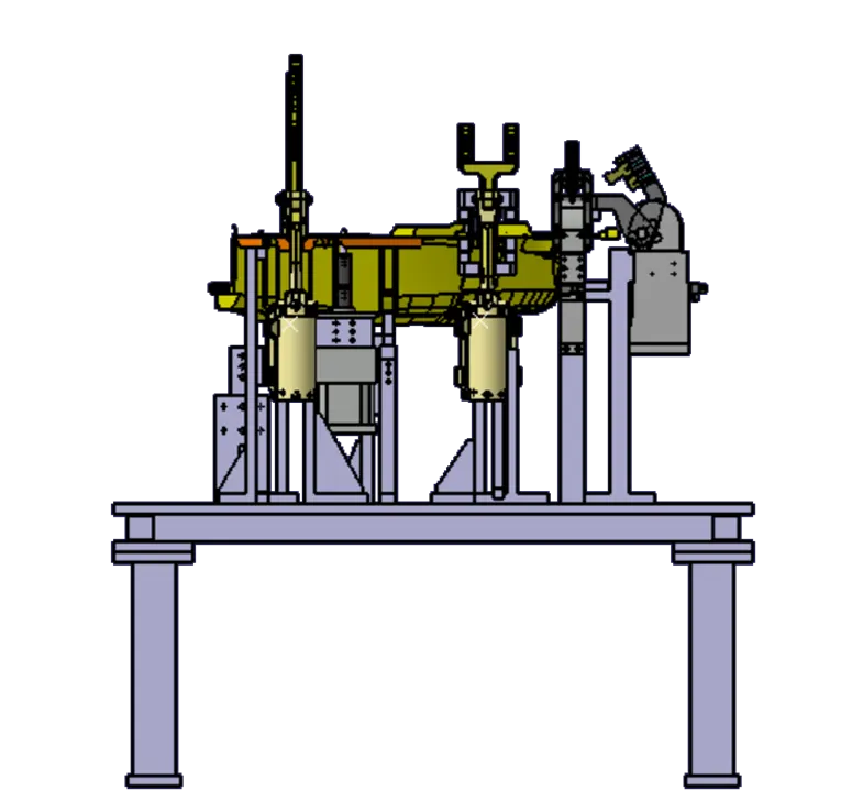
Fig BASE PLATE FINAL SIDE VIEW(WITH PANNEL)
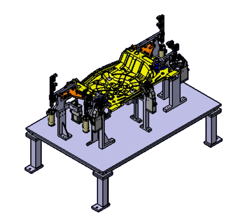
Fig BASE PLATE FINAL ISO VIEW(WITH PANNEL)
Conclusion
Hence as per the design was named as (P001_Z01_ST01_00_00) and the base unit names as (P001_Z01_ST01_01_00_BASE_UNIT), PIN_UNIT(P001_Z01_ST01_02_00_PIN_UNIT) , CLAMP_UNIT(P001_Z01_ST01_03_00_CLAMP_UNIT), AND REST_UNIT(P001_Z01_ST01_04_00_REST_UNIT)designed using CatiaV5 Successfully