Week 7- Base Unit Design Challenges 2
Design of base unit.
the base units mainly consists of various parts as below.
1.base plate.
2.pedestal.
3.Trunking channel.
4.valve box.
5.Eye bolt.
6.Holes along with tapping at certain co-ordinates for fixing the units.
7.Floor plate.
8.Design considering welments required or bolting requirement at certain locations.
1.Base plate design.
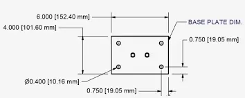
The base plate is selected may be of material of SS or MS for locating the unit assembly on it.The shape of plate may be squared or rectangular.
the plate selected here is of dimension 1600*1200 rectangular C/S .These size is selected according to requirement of the operation and cost constraint.The base plate requirement should be in a away that it should bear the required load,vibrations and shocks of operation.
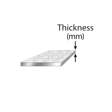
The thickness is generally taken of 50mm.
2.Pedestal design.
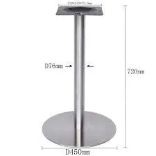
the pedestal is generally used for transmitting the load in required desired manner to the ground.and provide sufficient balance to the assembly .The pedestal generally used are of 4 nos.The design for pedestal is total load /no of legs.The size of each pedestal and length is selected according to load ,space constraints.The pedestal should also be able to balance the assembly in proper way.The pedestal thickness selected here is holoow pedestal with 150*150 size.
3.Trunking channel .
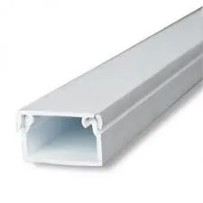
The trunking channel is generally used to routing the electrical ancillaries or pneumatic tubes required for pneumatic or sliding operations.
the required space in trunking channel is selected and the variation in size is also generalised as lengths of wires and tubes may vary accordingly.
here the trunking channel size selected is of 250*250.
4.Valve box.
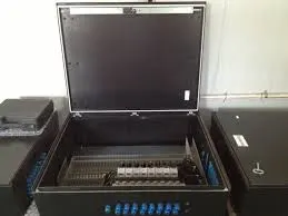
valve box is the area to locate the valves of each cylinder in certain area so that the operation is seamless and valves of cylinder required for operation are located into it.
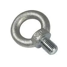
5.Eye bolt.
Eye bolt is generally used for lifting the fixture i may be due to operation change of transportation from supplier to OEM.The sufficient holes along with tapping is provided in the plate.
6.Holes with tapping at certain locations for placing the fixture units.
The holes at certain location are drilled in XY co-ordinate system so that the fixture units riser can be easily fixed on the base plate.
the bolts used may be of various types like M6 or M8 sizes .
7.Floor plate.
The floor plate is used for attaching to the pedestal to increase the surface area for proper balance.and aesthetic design.The design may be of rectangular or square sizes.
8.Design considering welments and bolting required at certain locations.
At certain location welding may be required for asembling the various parts.so the required space constraints and locations are provided.