Week 7- Base Unit Design Challenges 2
PROJECT TITLE: BASE UNIT DESIGN
Aim:
To design a base unit with all weldments for the given car panel and to design the complete fixture assembly with all the required units.
Abstract:
In this project the base unit is designed for the fixture having all the other units like pin unit, clamp unit, rest unit,etc., The base unit is designed considering all the fundamentals of the design.
Introduction:
Base unit:
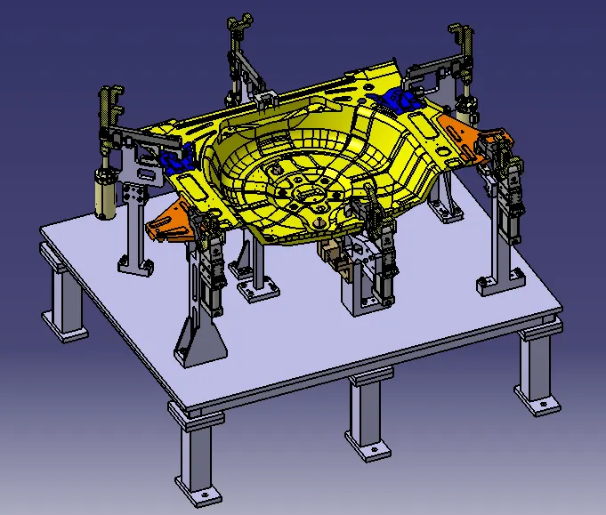
Fig shows: An assembly of a fixture with the base unit
- A base unit is the unit designed to mount all the other units (Clamp unit, Pin unit, Rest unit,etc.,) of the tool.
- It also holds other parts necessary for a tool like pneumatic valve box, Trunking channel, base plate eye bolt will also be mounted on to a base unit.
- It is the fundamental component of the fixture because all the other components are mounted over it. So every fixture has base unit.
- The base unit is different according to the panel, design of clamp system, location system, etc.,
Parts of the base unit:
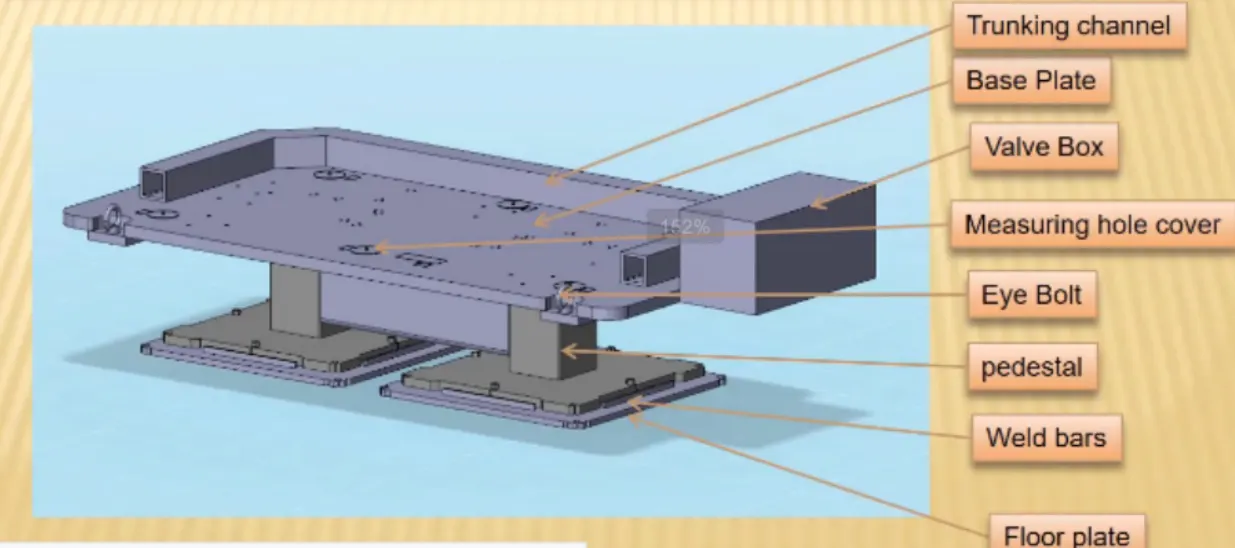
Fig shows: Parts of the base unit
Base Plate:
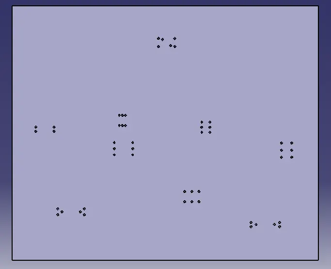
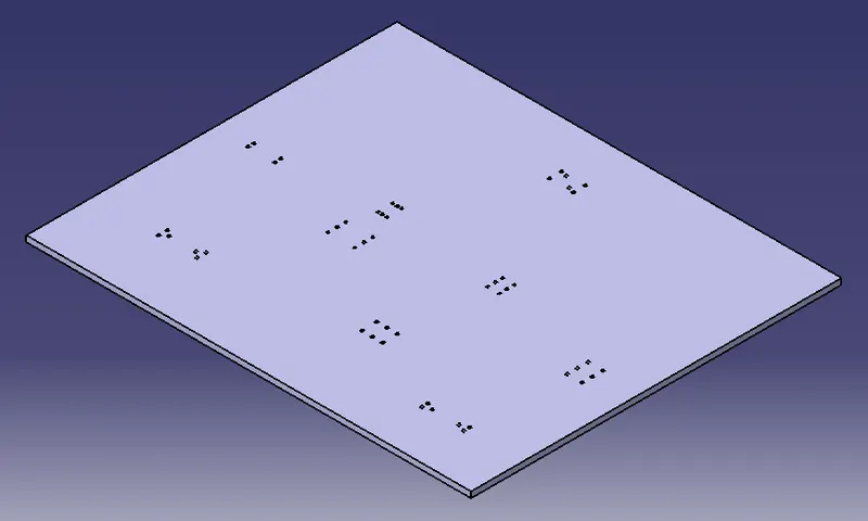
Fig shows: Base plate of a fixture
- The base plate is a plate of 25mm to 40mm thickness.
- It has a no of holes drilled on it which acts as mounting points for clamp unit, pin unit,etc.,
- It holds the trunking channel, eye bolts, valve box and some other parts.
Pedestal:
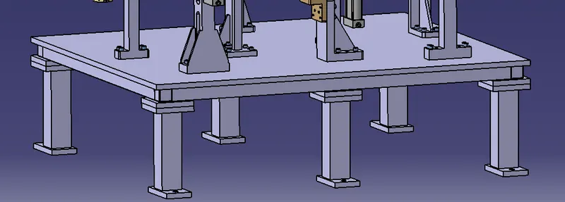
Fig shows: Fixture having no of pedestals
- It is used to connect the base plate with the floor plate.
- It withholds the entire tool onto the floor plate. Hence it must be strong and rigid enough to withstand the forces and weight of the tool.
- It can be a standard part or a make part, depending on the size and height of the fixture.
- Standard pedestal are available in different heights.
- Pedestals are also available in different inclinations.
- Depending on the size of the base plate, the number of the pedestal for a fixture can vary for load distribution.
Trunking channel:
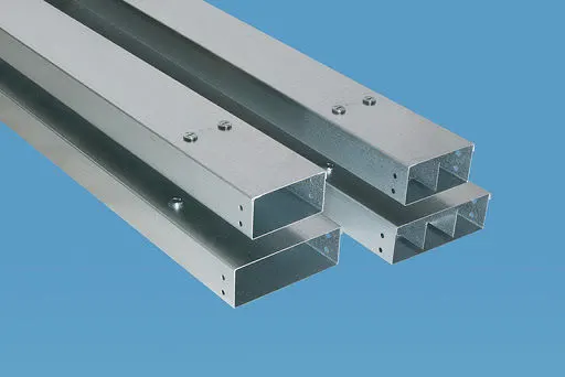
Fig shows: Trunking channels
- Trunking channel is a duct that carries all the electrical and pneumatic connections like wires and hoses for units of the tool.
- It has some thickness of few millimetres.
Valve box:
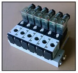
Fig shows: Valve box
- Valve box is a standard part which contains all the valves for the pneumatic units. The valve box is the box which includes different solenoid valves.
- The pneumatic fixtures work on air pressure provided to it.So the arrangement of air pressure inlet and outlet is done within this valve box.
- The trunking channel includes all the pressure inlet cables going to the pneumatic parts of the fixture & protects them from being damaged while operation is in process.
Eyebolt:
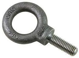
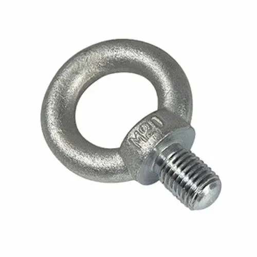
Fig shows : Eye bolts
- Eye bolts are the bolts that are used to lift the fixture for transportation by inserting hooks into them.
- Generally M20 bolts are used as eye bolt which are bolted on the base plate.
- The main purpose is for transportation, sometimes forklift holes will be provided.
Floor plate:
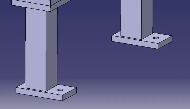
Fig shows: The adjusting mechanism at the pedestal base plate
- They are also known as foundation plate. They are grounded by using a fixed bolt.
- 10 mm clearance should be given between the pedestal base plate and floor plate.
- Weld bars are welded after the levelling is done by using levelling screw.
- Weld bars are steel plates along the sides of the base plate of a pedestal.
- They are welded to permanently maintain the proper position of the fixture.
Design methodology:
The points need to be taken into account while designing the base unit are:
Working Height:
- It depends on the nature of the manual or robotic welding fixture.For manual fixture we need to consider the working height of the worker, standard of a specific country will apply. ( In few countries human height is heigher or lower e.g. The USA, Japan)If the base structure is made with a base plate having tubular structure welded below it, we can reach to a height of 100 mm to 250 mm.In this case to reach the working welding height, we need to provide an additional some leg structure which may have top and plate welded to the tube.As a designer its important to know how big base plate or bigger base welded structure will be handled during the fabrication & handling process. The special case needs to take care of flatness if the base size is very long.
Fig shows: Eye bolt
-
Depending upon the weight eye bolt size are selected for lifting holes on the base plate. Generally 4 eye bolt provision is made. We also need to select the location of eye bolt considering the rope/ belts used while shifting the structure or complete fixture are not damaging any units(rest,clamp or location units) nearby.Most of the OEM makes 4 dowel holes at 4 corners and put small aluminum plate marking X,Y &Z coordinates of dowel holes. If the base length is too long few OEM's follow the methodology of having dowel holes at 500mm distance.
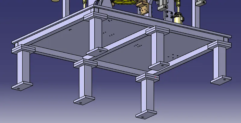
- The base unit of the fixture must be strong enough so that deflection of the fixture is as minimum as possible. In this desogn, there are 6 pedestals provided for thw base plate. To support the base structure 50x50x2xL Square tubing is used and the pedestal support is provided with 80x80x5xL Square tubing This deflection of a fixture is caused due to the forces of welding, clamping of the workpiece.The base unit of the fixture should have the mass to prevent vibration & chatter.The base unit may be built from a simple section so that other unis are fastened with screws or welded necessarily.
- Those parts of the fixture that remain permanently with the fixture may be welded. Those parts that need frequent changing may be held with screws.The base unit should be parallel to the floor, to adjust it there should be the provision of the height adjusting mechanism.
Fundamentals of Base unit:
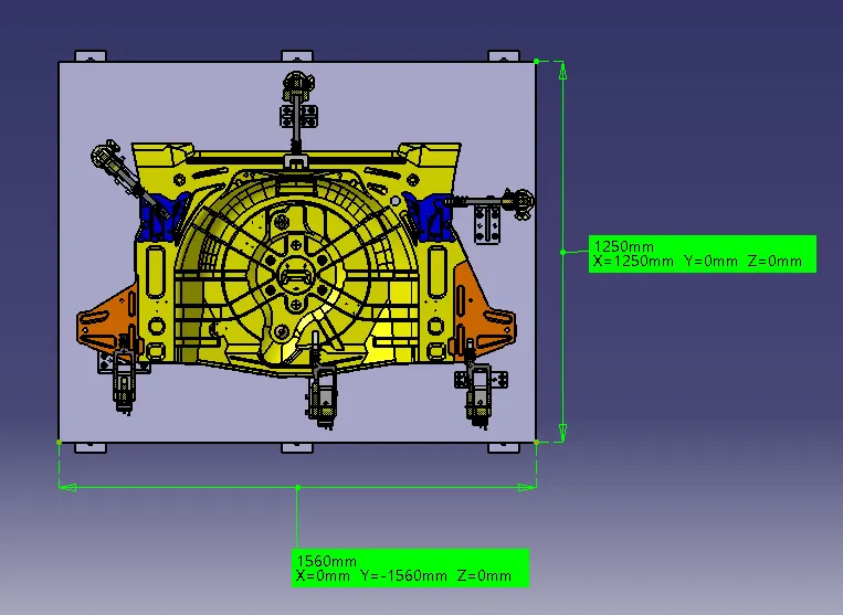
Fig shows: Base plate size
- A base plate size should cover all the units with its outer periphery including the opening.
- A base plate is always preferred to be designed with respect to BCS Coordinates.
- A base plate should be drilled with datum holes/ measuring holes in line with a pitch of 1000 m in general.
- The number of datum holes depend on the size of the base plate.
- Datum holes should be drilled at nominal values of co-ordinates and in terms of 50 and 100. Example, X=100, Y=-600, Z=250.
- Datum holes should be covered with cover plates.
Various units of the design
Fundamentals of pin unit design:
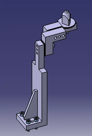
Fig shows: Pin unit
It is necessary to have 2 pins to locate a car panel where one pin must arrest 4 way(translational) movement and the another one must arrest 2 way(rotational) movement of a car panel.
The axis of the car panel hole and the axis of the pin should be same in general.
The pin tolerance for a geo pin will be of closer tolerence of -0.15mm & for the re-spot pin is -0.28mm.
- Pin should engage at 3 to 5 mm from car panel entry surface.
- All pins should be accommodated with 2-way adjustable shims irrespective of direction of arresting.
- Round pins should be used incase of 4way arresting of car part if the hole is round.
- Round pins can be used for 2 way arresting of car parts only if the hole is slotted.
- Diamond pins should be used for 2 way arrresting of car part if the hole is round.
- Diamond pins should be used incase of 4 way arresting of car parts if the hole is slotted.
CLAMP UNIT:
- A clamp unit is a unit designed to clamp/hold the car panel with NC blocks/Mylars/Rest by using a pneumatic clamping cylinder.
- Some of the parts of the clamp unit is clamp arm, finger, rest/backup, L-block, shims, Risers and Pneumatic cylinders.
- Types of clamp units:
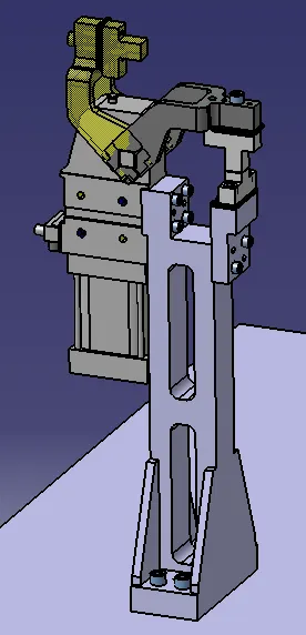
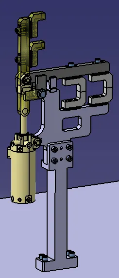
Power clamp unit Swivel cylinder clamp unit
Fundamentals of clamp unit design:
- It is preferred to design clamp unit with pivot centerline in-line with clamp surface. When possible upto 25mm offset can be acceptable.
- For sigle angular clamping, it is recommended that the centerline of clamp pivot be positioned on plane that is created by surface being clamped, upto 15 degree off normal pivot location can be used in extreme cases where recommended clamping condition cannot be satisfied.
PURPOSE OF CLAMP UNIT AND REST UNIT
- The purpose of clamping tools is to securely hold the workpiece in position without obstructing the production process.
- It prevents the distortion during welding process and other processes.
- High clamping forces combined with compact dimensions are therfore the most important requirements for a clamping tool. For this reason, clamps are also equipped with mechanical transmission gear units.
3-2-1 Principle achieved by,
Pin unit:
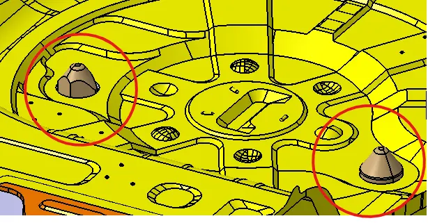
Fig shows: Pin unit arresting 6 DOF
- Pin unit is a part of the 3-2-1 locating principle of fixture design.
- It restricts 6 degrees of freedom of the part.
- This is sometimes provided with the clamp unit when two panels are to be located for any operations like welding.
- 2 pins are used to restrict 2-axes(x & y) translational movements and z-axis rotational movements results in arresting of 6 degrees of freedom.
clamping and resting:
- The 3-2-1 principle is the fundamental principle of all fixture design. While designing a fixture a major part of time is spent in locating the workpiece in the fixture.
- The best & the most effective method of part location is referred to as the 3-2-1 method. Fixtures work on the 3-2-1 principle.
- 3 locators or supports are placed under the workpiece which establishes the part plane. Three locators are generally positioned at the primary locating surface.
- This restricts 2 axial movements downward & upward and 4 radial movements. As a result the 3 locators arrest six degrees of freedom.
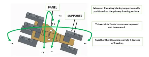
Fig shows: 6 DOF which are restricted by the locators or the clamps
- Thus by using 3-2-1 principle, introducing a minimum of 3 clamping & resting blocks will restrict 6 DOF( 2 axial translational about z-axis & 4 rotational about the x&y axes respectively).
- Remaining 6 DOF are restricted by introducing Pin unit of minimum 2 nos.
- Clamping- The process of holding the workpiece in the jig/ fixture is called clamping. The primary devices used for holding the workpieces are clamps/clamp unit.
- Resting - The car panel will rest on the rest unit. It resists the clamping force of the finger exerted by the clamp cylinder and thus clamps the car panel.
Design tree:
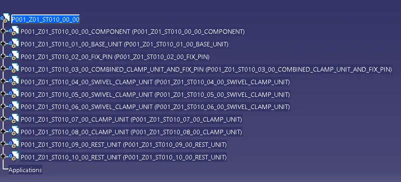
- It is the process of naming all the assemblies and parts in the specific standards. Different customers have different set of standards to structure a design tree.
- It is an important process which helps us to identify a specific part or assembly as to which project or assembly it belongs to.
- This helps us to avoid the errors during design study, manufacturing, assembly,inspection, etc.,
- If the parts or assemblies are not properly or the design tree is not structured properly, it will create confusion in understanding the design and assembly which may lead to errors.
- Naming of a fixture or a unit or a part gives their place in the specific project or assembly or zone.
- It helps us to identify the quantity of items of same type or different types that are being used in the assembly.
PLP Location and clamp plan:
PLP (Principle Locating Points):
- Principle locating points are the points that are used for the accurate location of the panels sub-assemblies to maintain the geometry of the assembly.
- There are lots of holes on the panel which are not accurate due to stamping operations. So the PLP are defined in the drawings.
- The PLP holes must be very much precise.
Clamp plan:
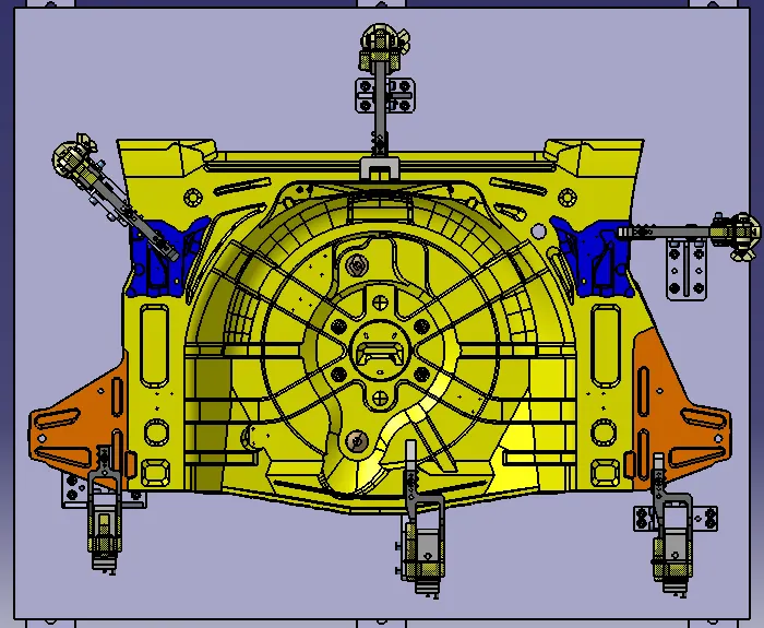
Fig shows: Clamp plan
- It provides information of location of pins, clamp units, rest units,damp units.
- It is the important input from the customer end.
- The clamp plan/ position should not be changed without the knowledge of the customer.
- It is allowed to change the design little bit here and there but the input design data about the clamp position or pin location must not be changed.
- In clamp plan there is clamp unit,pin unit and it is more detailed. It also gives the Y and Z coordinates from where the designing process of fixture can be started.
Material used:
In general, the materials used for Mylars, Clamp arm, shims, block, blades & risers are:
- Mylars: UHMW, Nylon66, PP, Teflon (polytetrafluroethylene (PTFE). Materials of clamp block and rest block to be decided as per the A class panel or B class.
- Clamp arm: SAE 4140 or SAE 1045.
- Shims / Spacer: S.A.E. 1010 CRS FULL HARD, COLD ROLLED STRIP STEEL S.A.E. 1010 FULL HARD, S.A.E. 1020 HRS, etc.,
- Block: STEEL ASTM A-36, NM STAINLESS, STEEL ASTM A-36, SS type 303 or 304,etc.,
- Blade: STEEL ASTM A-36,etc.,
- Riser: STEEL ASTM A-36,etc.,
HARDNESS:
In general, the hardness of the materials for pins, pin retainers, shims, shim block, blades and risers are 55-60 HRC to a depth of 0.5-0.7 mm after grinding.
SURFACE FINISH:
In general, the surface finishes of the materials for pin, pin retainer, shims, shim block, blades and risers are:
- Clamp arm: Munsell No.3.75YR6/14 safety orange.
- Shims/spacers: BLACK OXIDE FINISH (SURFACES TO BE FLAT AND PARALLEL TO WITHIN 0.012 mm T.I.R.)
- Riser: SURFACES TO BE FLAT, PARALLEL & PERPENDICULAR TO WITHIN 0.015 T.I.R.
Images of the design:
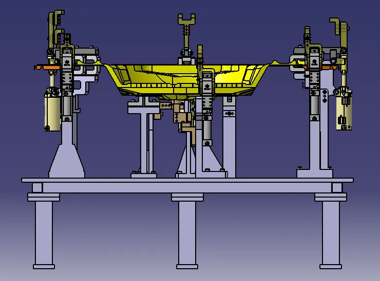
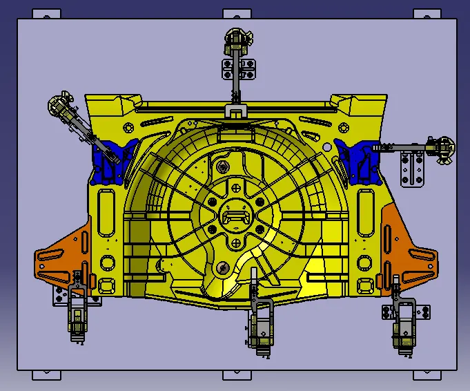
Fig shows: Front view of the assembly Fig shows: Top view of the assembly
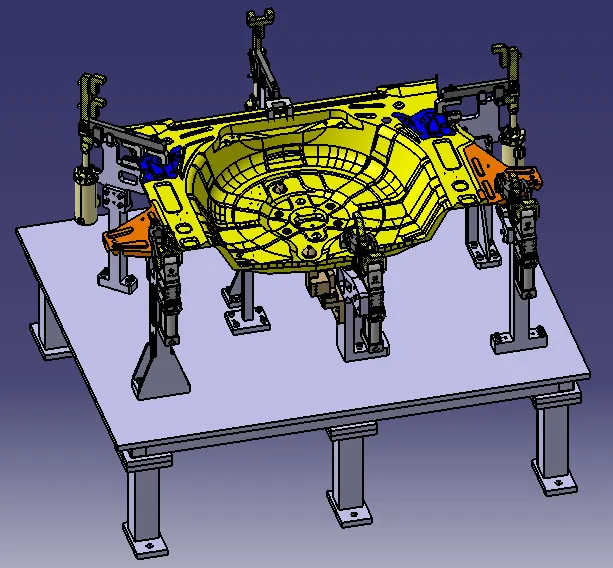
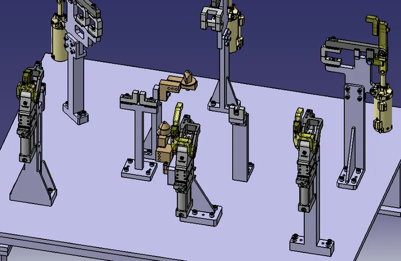
Fig shows: Assembly of the fixture Fig shows: Positions of all units
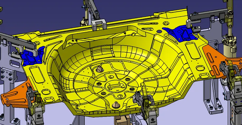
Fig shows:Pin and Clamping positions
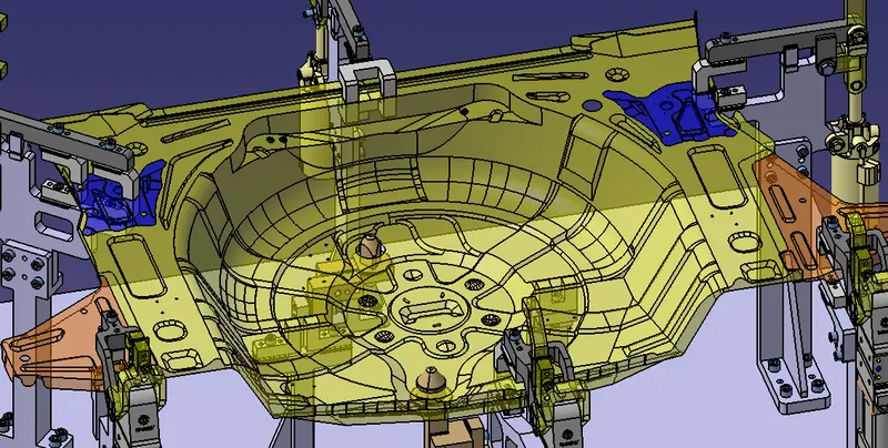
Fig shows: Transparent view of the assembly
CONCLUSION:
Thus the design of the base unit with all weldments for the given car panel including all the units are done as per the fundamentals of the design.